


SIG Four-Star 60 Build

 04-13-2019, 01:10 PM
#104

Thread Starter
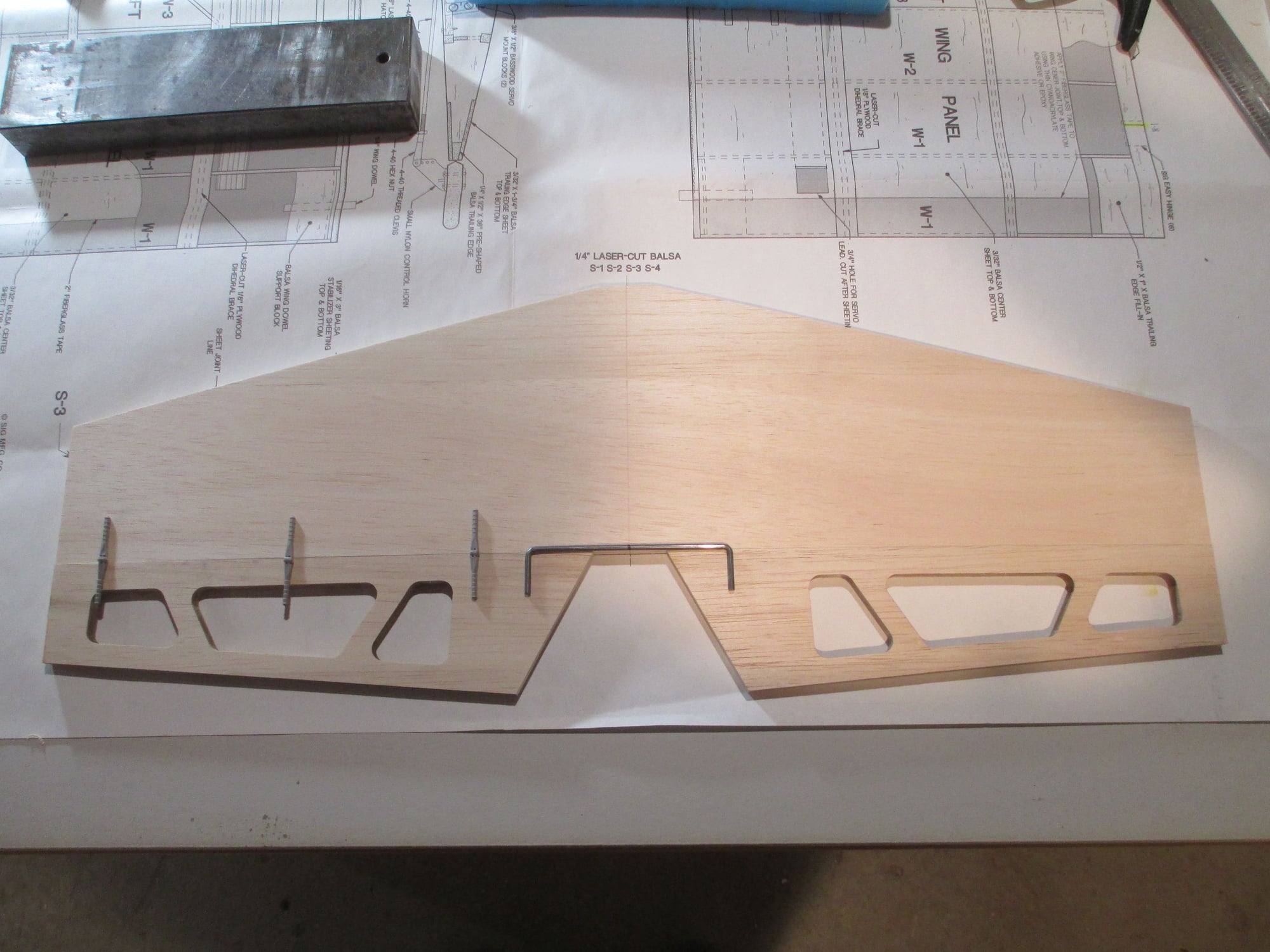
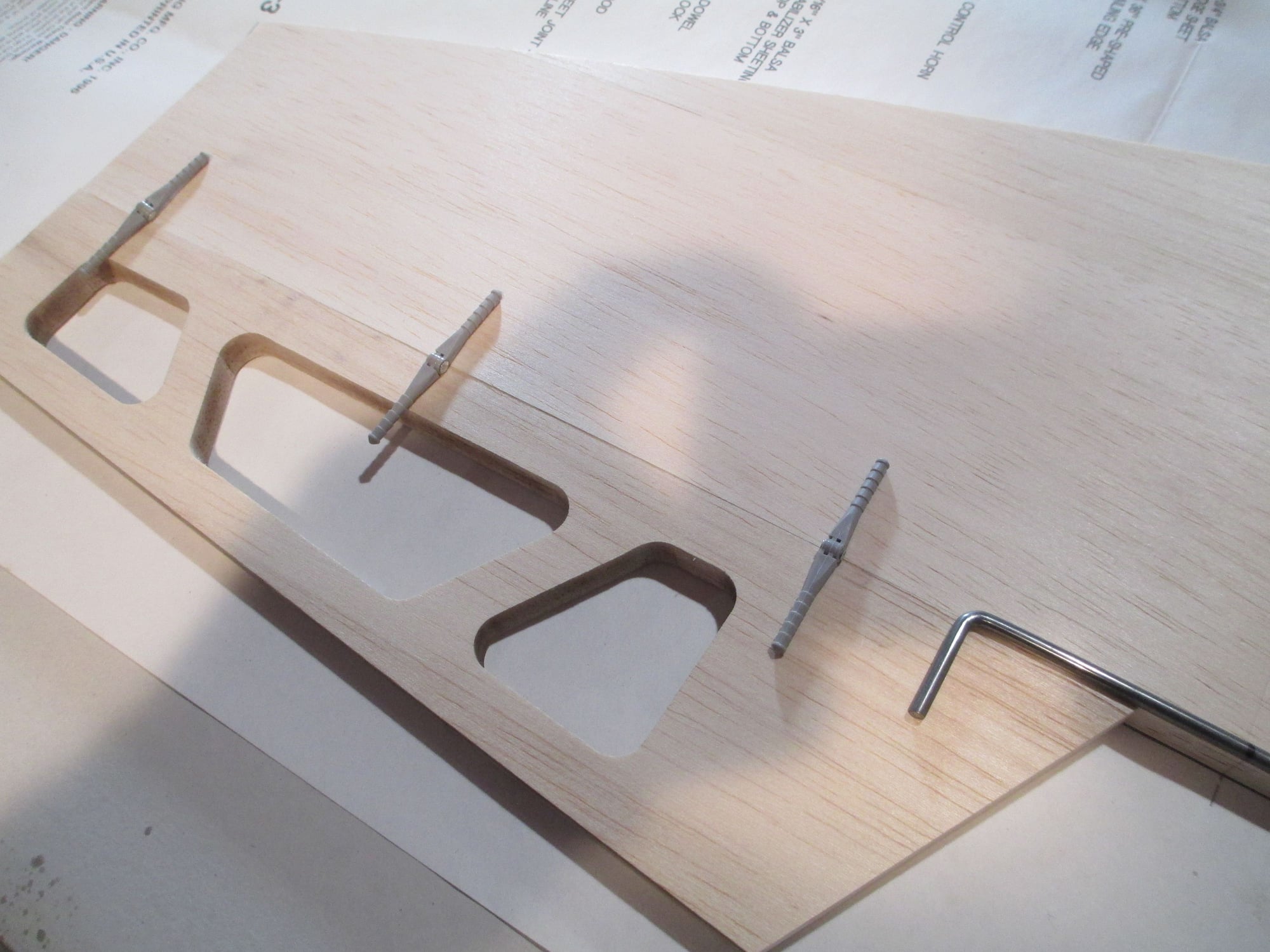
Three Robart hinge points used on each elevator half.
Marked the exact location of the 1/8" wire joiner. I did this after I drilled and install all of the hinge points.
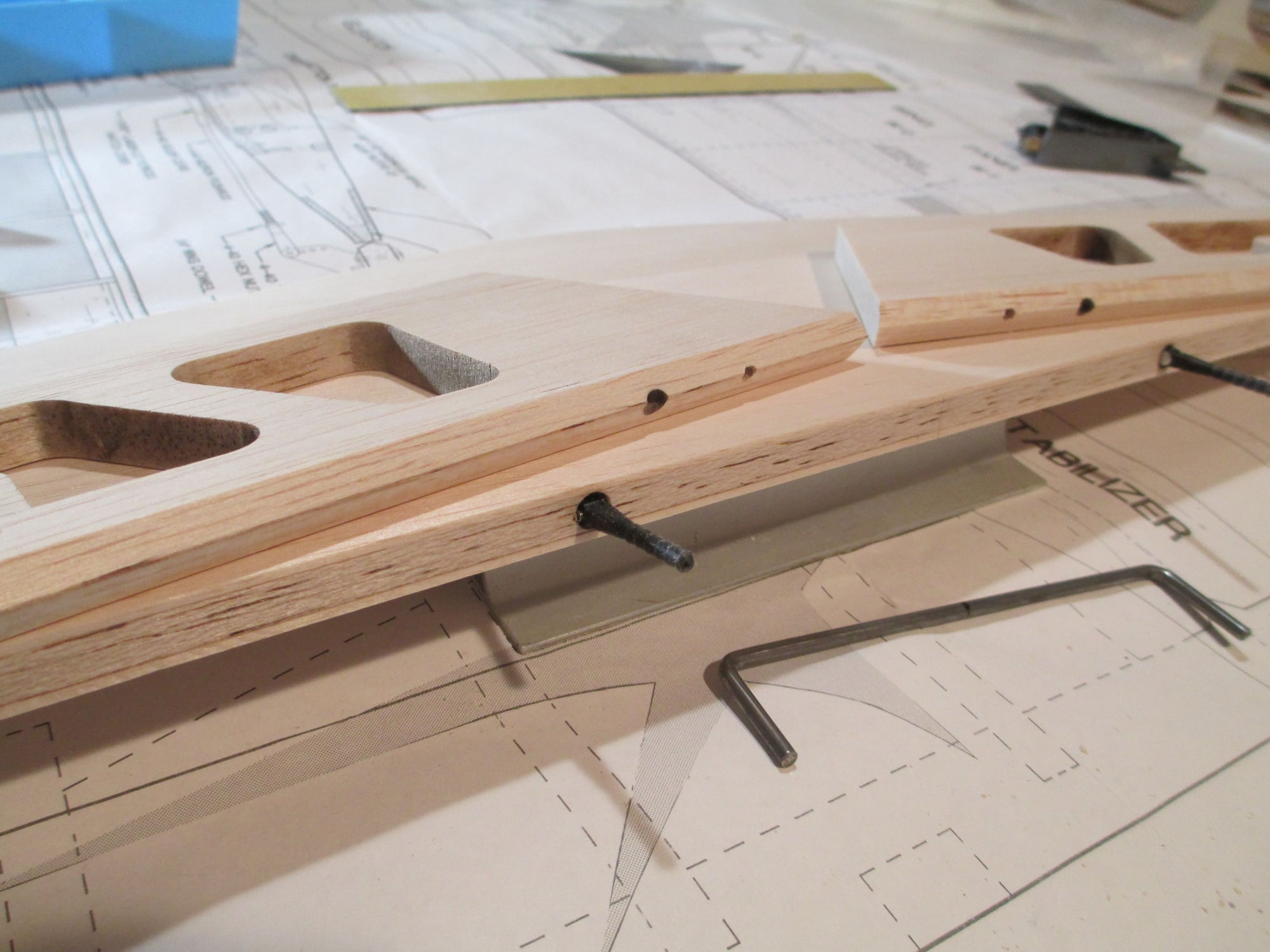
You can see the wire joiner holes have now been drilled.
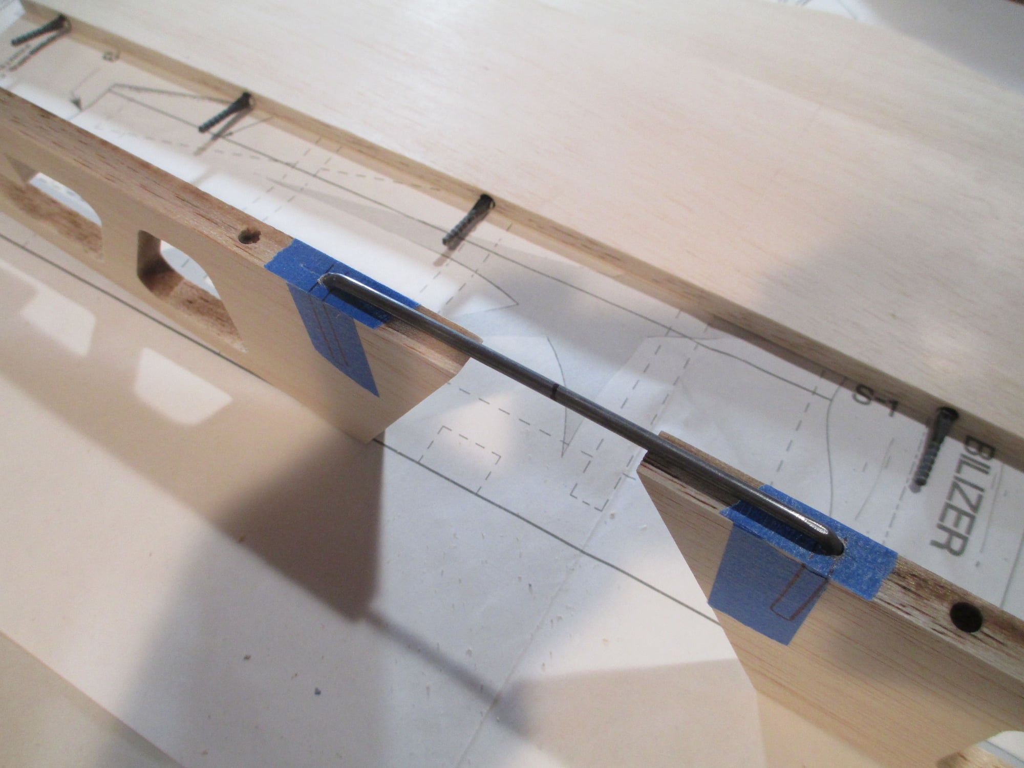
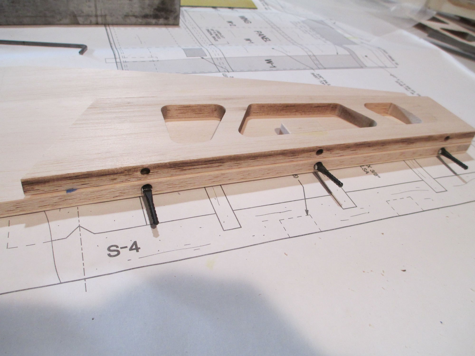
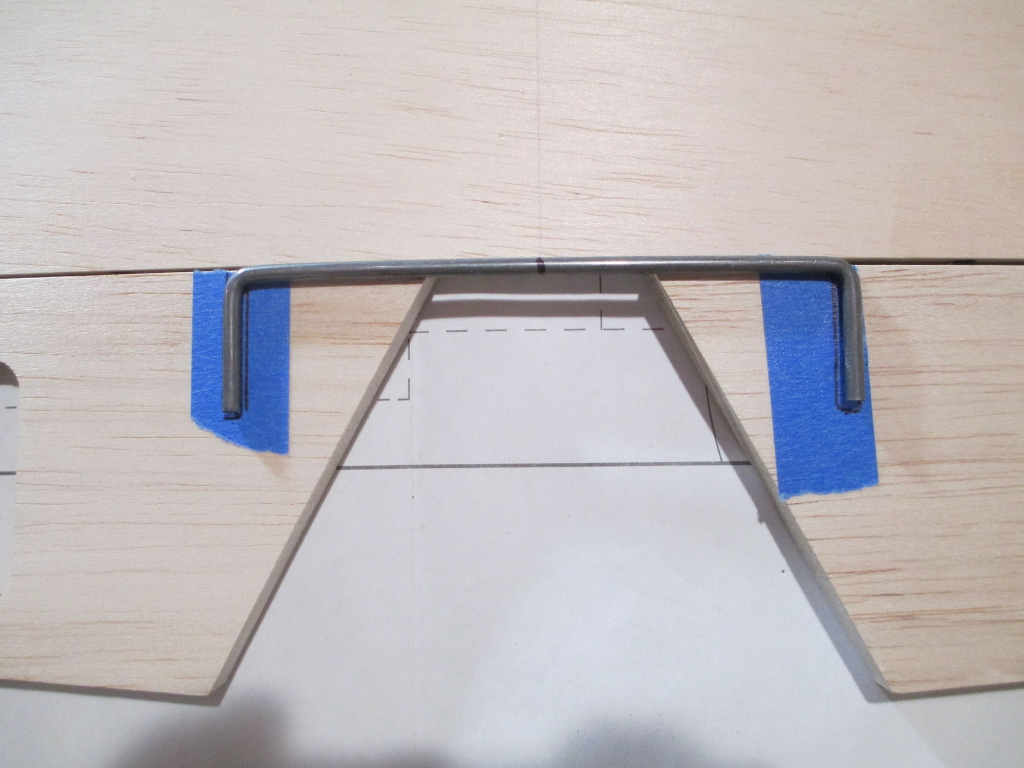
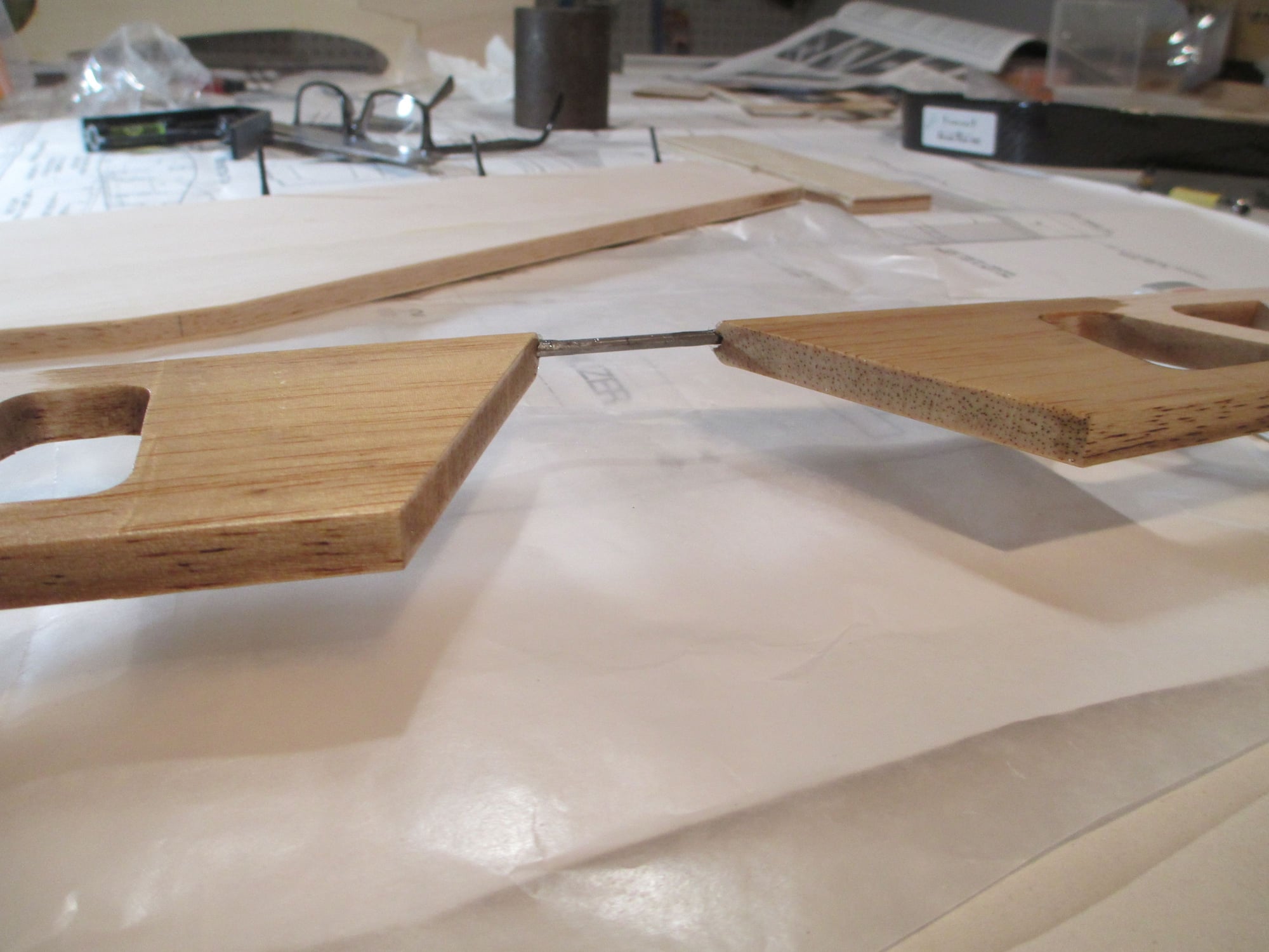
Test fit the joiner. Now I have to recess the joiner so it will sit flush with the leading edge of the elevator.

Notches are cut and now I'll mix up some epoxy and install the wire joiner to each elevator half.
 04-14-2019, 02:33 AM
#106
Thread Starter
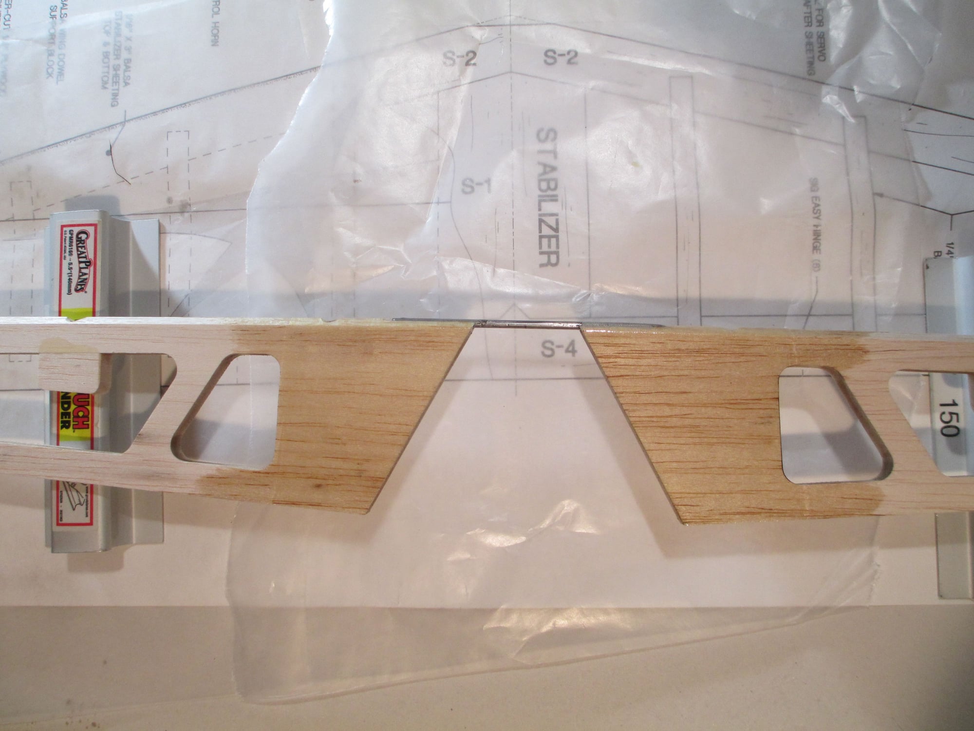
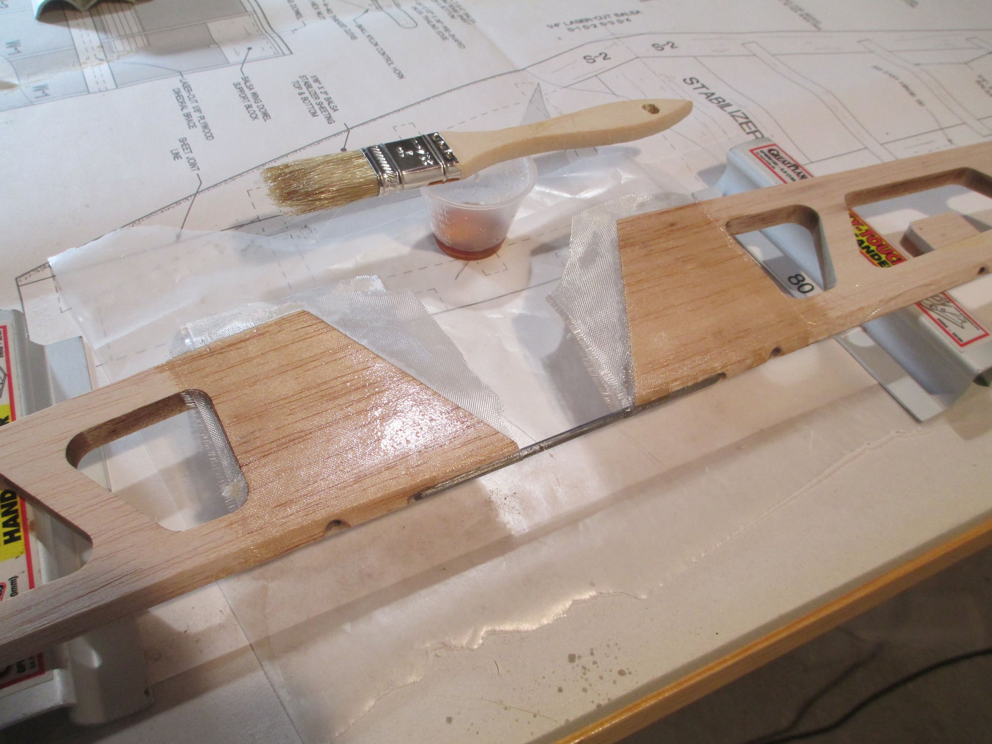
The excess fiberglass cloth has been trimmed and a second coat of resin has been applied
Care must be taken to make sure that both elevator halves are on the same plain.
3/4" Tri-stock reinforcement was added to the landing gear plate. This will also tie in F-2 former, adding additional strength.
Capped off the bottom opening with lite-ply. I think this plane will have legs soon!
04-14-2019, 08:51 AM
#107
Thread Starter
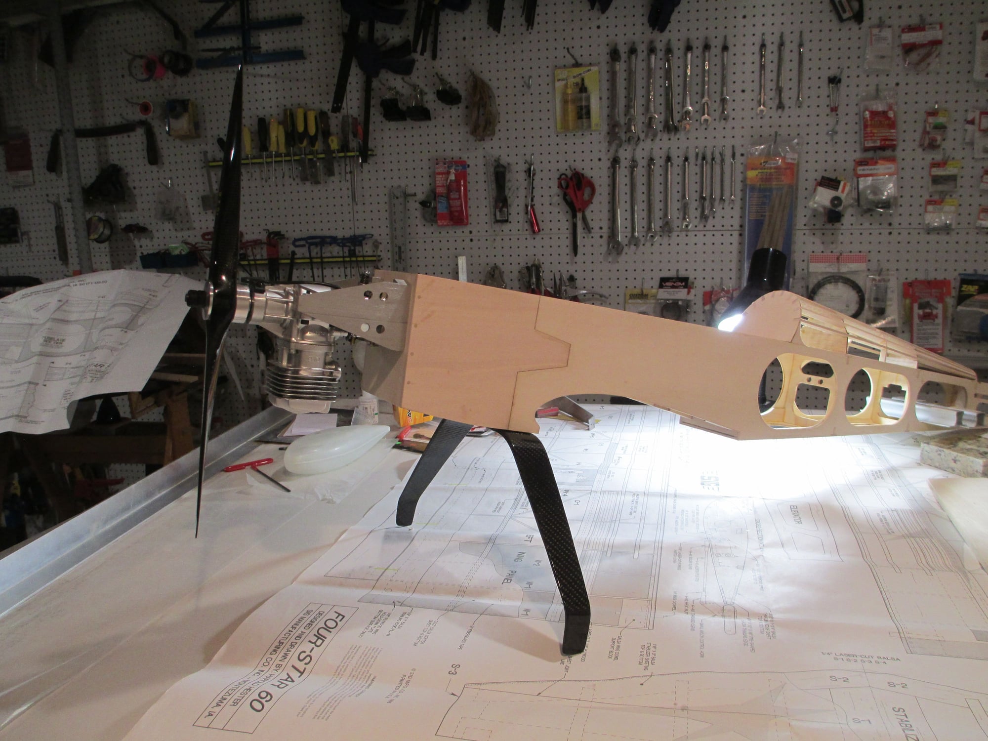
I was excited to mount the landing gear and see if I had the prop clearance I was looking for.
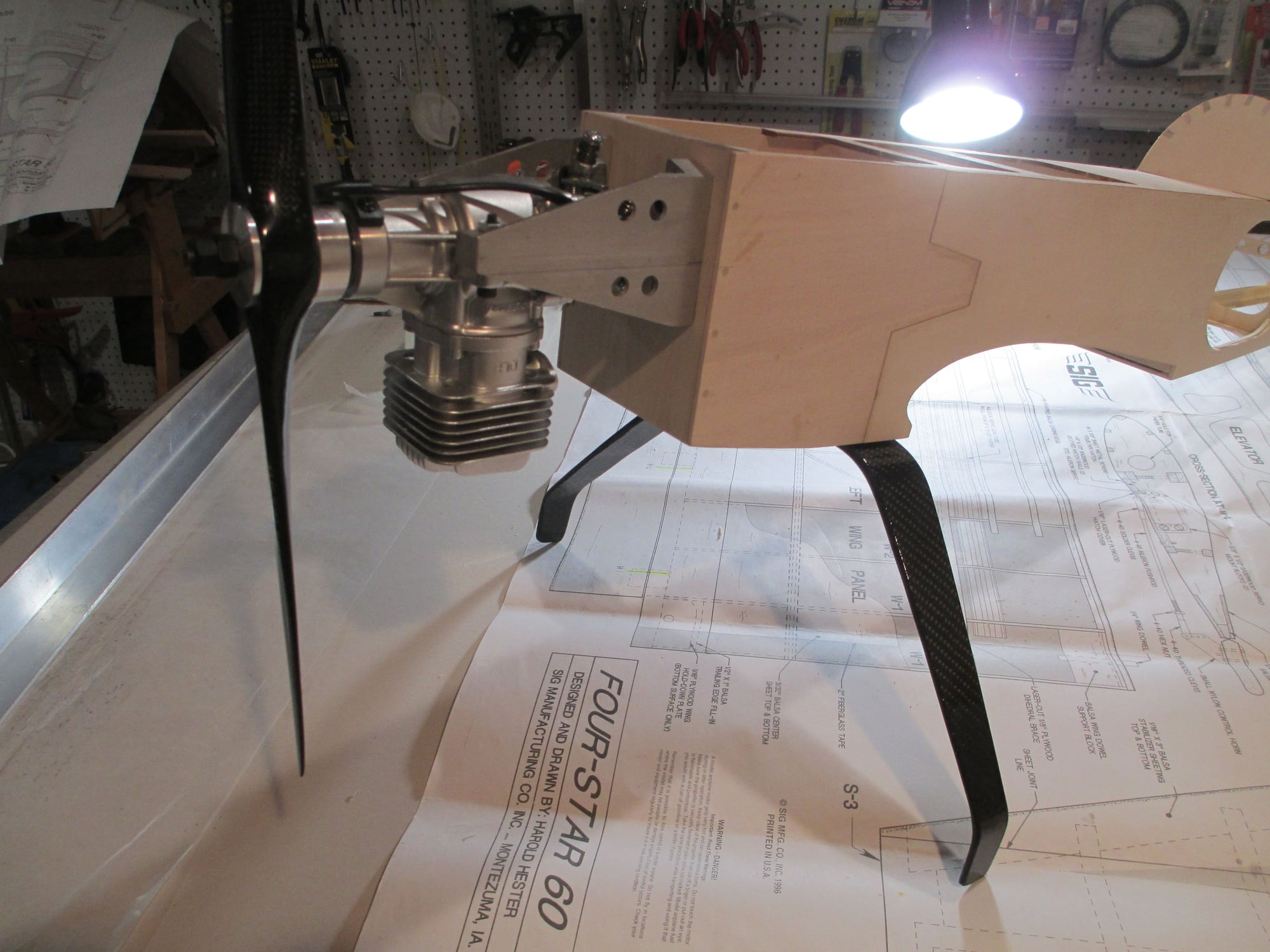
Running a CF 16x8 prop.
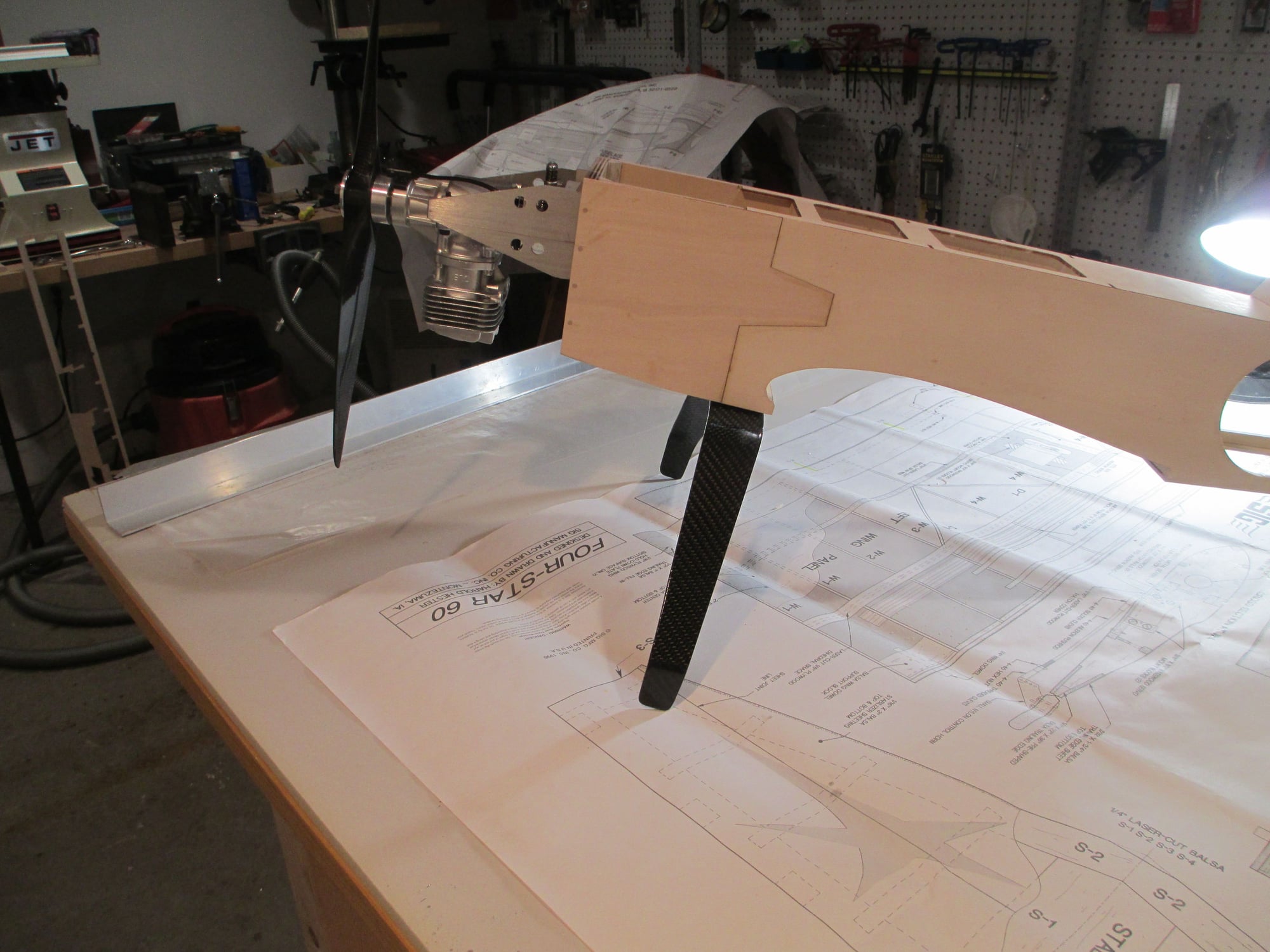
I've got the clearance I was looking for...
 04-14-2019, 03:00 PM
#108
Thread Starter
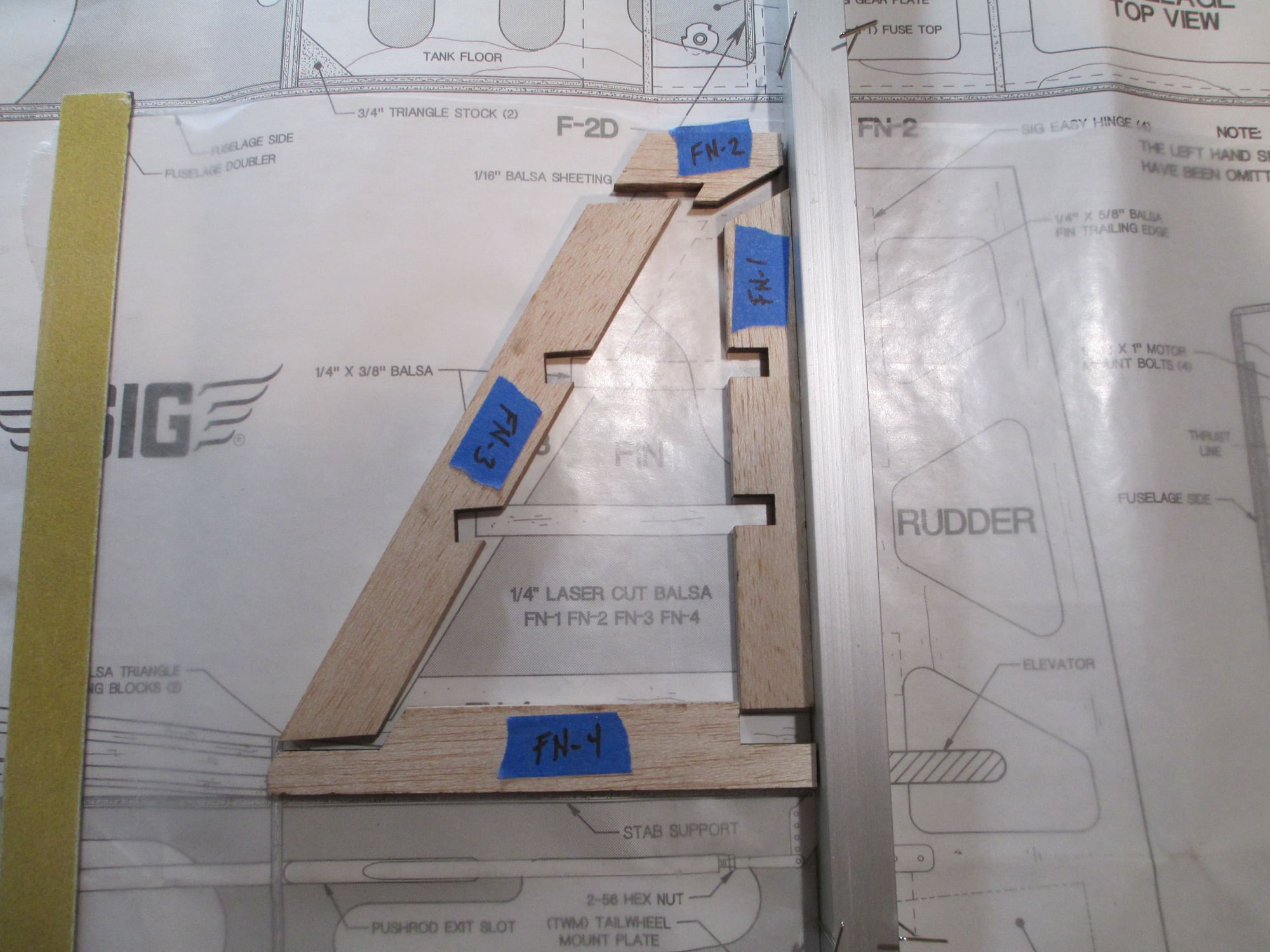
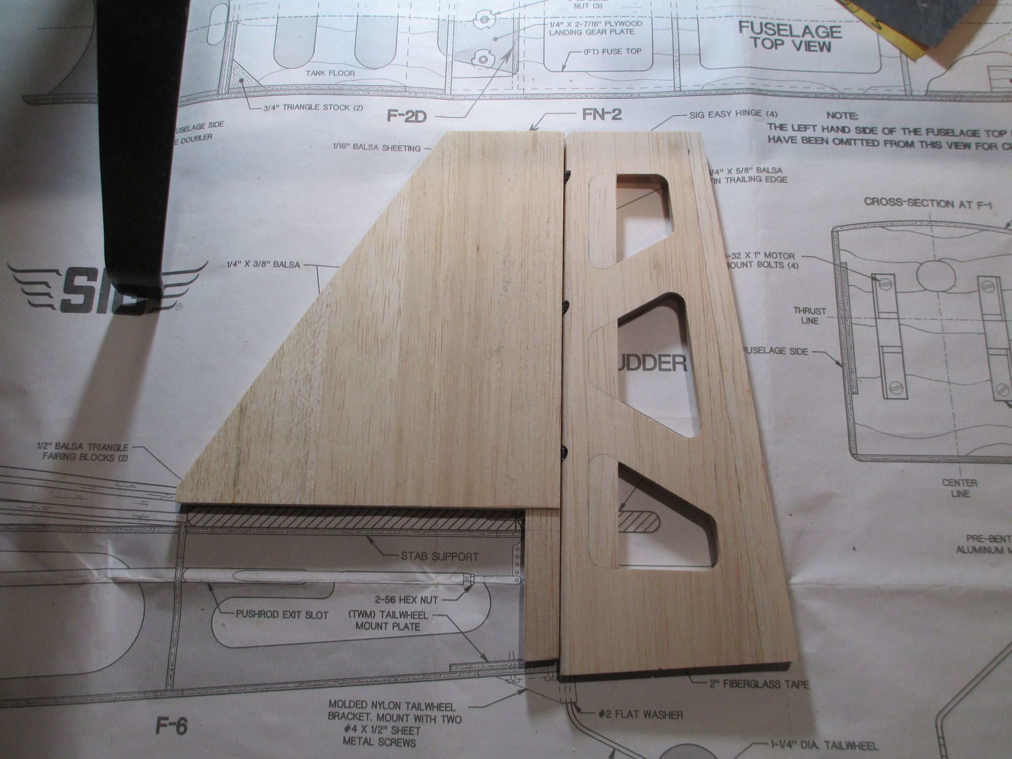
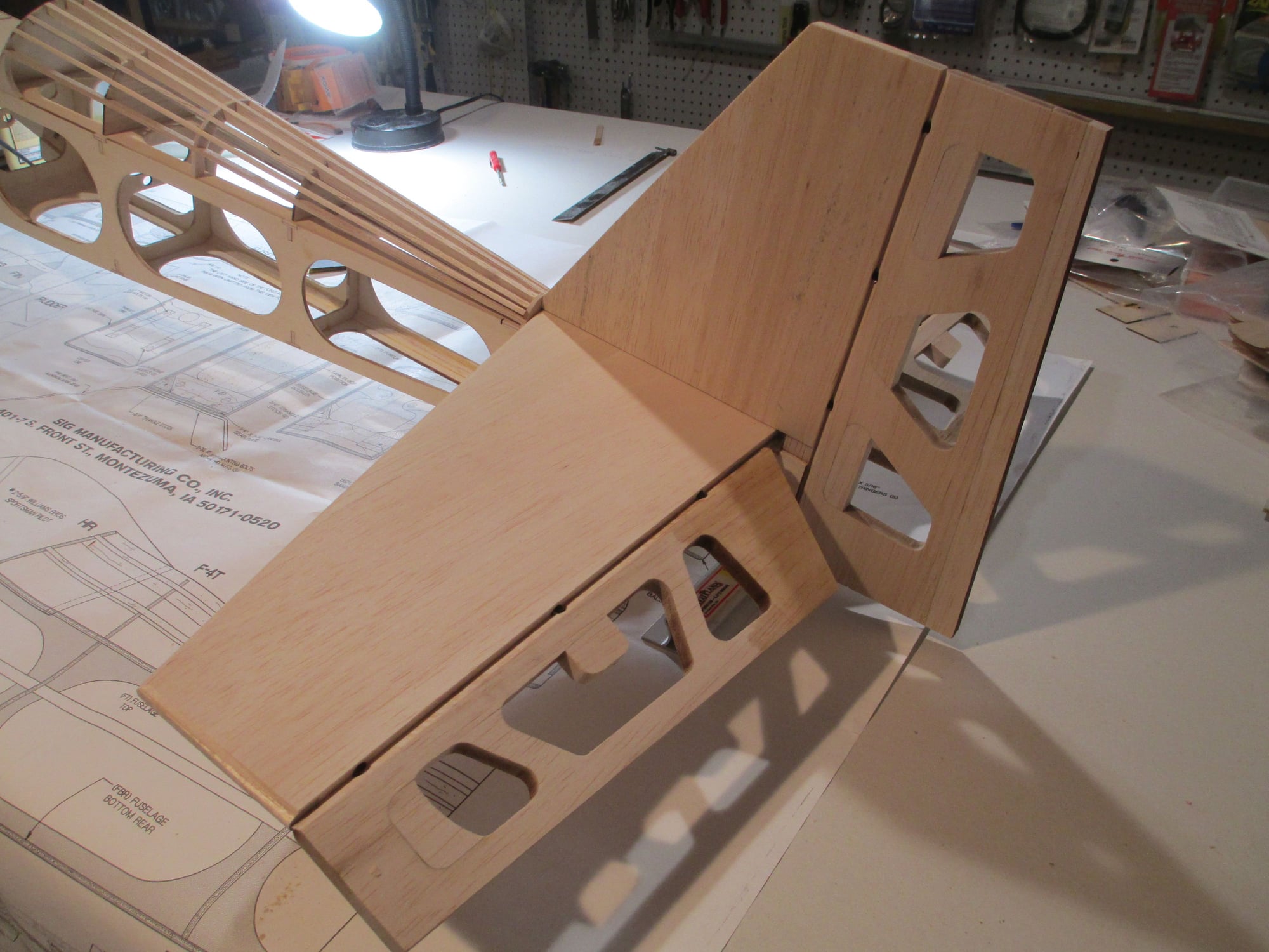
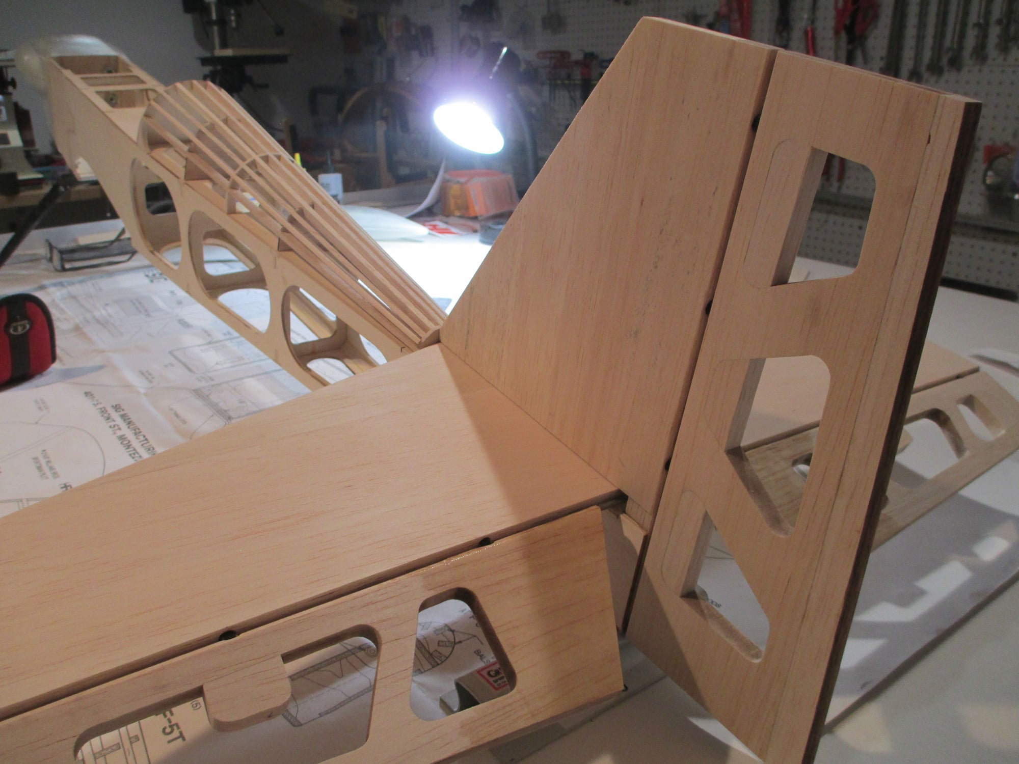
Construction has started on the fin. Parts labeled, checking dry fit next before glue-up.
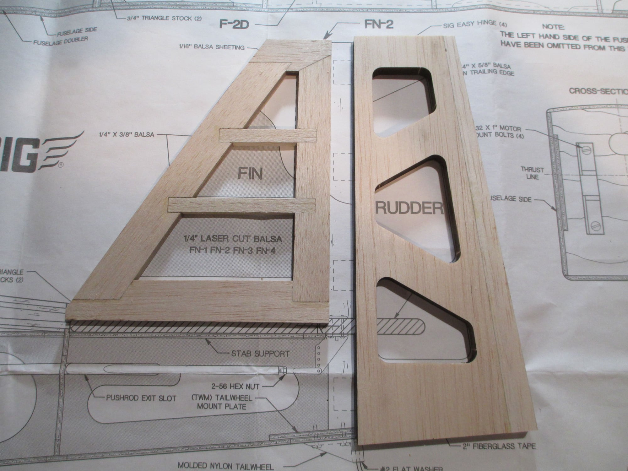
Notice that I extended the rudder a bit. It didn't amount to much, I used the bit of scrap balsa that was on the same sheet after I popped the rudder out. I like the proportions better. The fin will get sheeted next.
Last edited by VincentJ; 04-15-2019 at 05:27 AM.
04-16-2019, 08:58 AM
#109

Vincent, as usual your building skills are excellent. I look forward to seeing the finished product. Depending on how you intend to fly the airplane I would like to offer another suggestion. With the added power and prop disk if you intend to do maneuvers that require a fair amount of rudder input, you may want to consider adding a couple inches to the bottom of the rudder and a sub fin. The added bonus of this would be that the resting angle would be reduced a bit. Just something to consider.
04-16-2019, 10:26 AM
#110

I would also consider a little reinforcement on the bottom of the fuse behind the wing. Possibly some doublers on the side ..tied to the fuse bottom... I have seen many 4 stars break at this point.. its just a tad weak there...
04-16-2019, 10:44 AM
#111
Thread Starter
I did Foodstick, (see post #81). I added tri-stock right behind the wing (F-3) as well as additional plywood to the sides.
04-16-2019, 05:20 PM
#112
Thread Starter
Added a bit more structure to the landing gear plate. If you're wondering what the three holes are there for, it is just that I had re-purposed the original unused landing gear plate. The holes were where the landing gear was supposed to mount...
Last edited by VincentJ; 04-17-2019 at 03:31 AM.
04-17-2019, 03:25 AM
#113
Thread Starter
Vincent, as usual your building skills are excellent. I look forward to seeing the finished product. Depending on how you intend to fly the airplane I would like to offer another suggestion. With the added power and prop disk if you intend to do maneuvers that require a fair amount of rudder input, you may want to consider adding a couple inches to the bottom of the rudder and a sub fin. The added bonus of this would be that the resting angle would be reduced a bit. Just something to consider.
I appreciate all the comments and suggestions...
Last edited by VincentJ; 04-17-2019 at 05:37 AM.
04-17-2019, 05:31 PM
#114
Thread Starter
Sheeting is completed on the fin. Tomorrow I'll drill for the hinge points... Not a lot of time spent in the workshop with basketball playoffs in full swing.
04-18-2019, 05:57 AM
#115
VJ,
Nice work and I hear you about the basketball, I don't have time for anything with all of that going on!
Would you mind sharing where you had the carbon fiber gear custom made?
RS
Nice work and I hear you about the basketball, I don't have time for anything with all of that going on!
Would you mind sharing where you had the carbon fiber gear custom made?
RS
04-18-2019, 06:19 AM
#116
Thread Starter
If you're interested in getting the same gear, I can supply you with the dimensions that I gave them for this custom gear. Go Celtics (couldn't resist) !!!
Last edited by VincentJ; 04-18-2019 at 06:39 AM.
The following users liked this post:
Time2fly200 (08-29-2020)
04-18-2019, 09:39 AM
#117
Thanks VJ,
I just needed the gear info for future reference. I mostly scratch/plans build and am always looking for carbon fiber landing to fit whatever I'm building...Yes, Go Celtics! ( in the east of course )
RS
I just needed the gear info for future reference. I mostly scratch/plans build and am always looking for carbon fiber landing to fit whatever I'm building...Yes, Go Celtics! ( in the east of course
)RS
04-18-2019, 03:18 PM
#118
Thread Starter
Three 1/8" Robart hinge points were used to join the fin and rudder, one more will be added towards the bottom. If you look carefully you will see where I had to add blocking for the hinge points in the rudder.
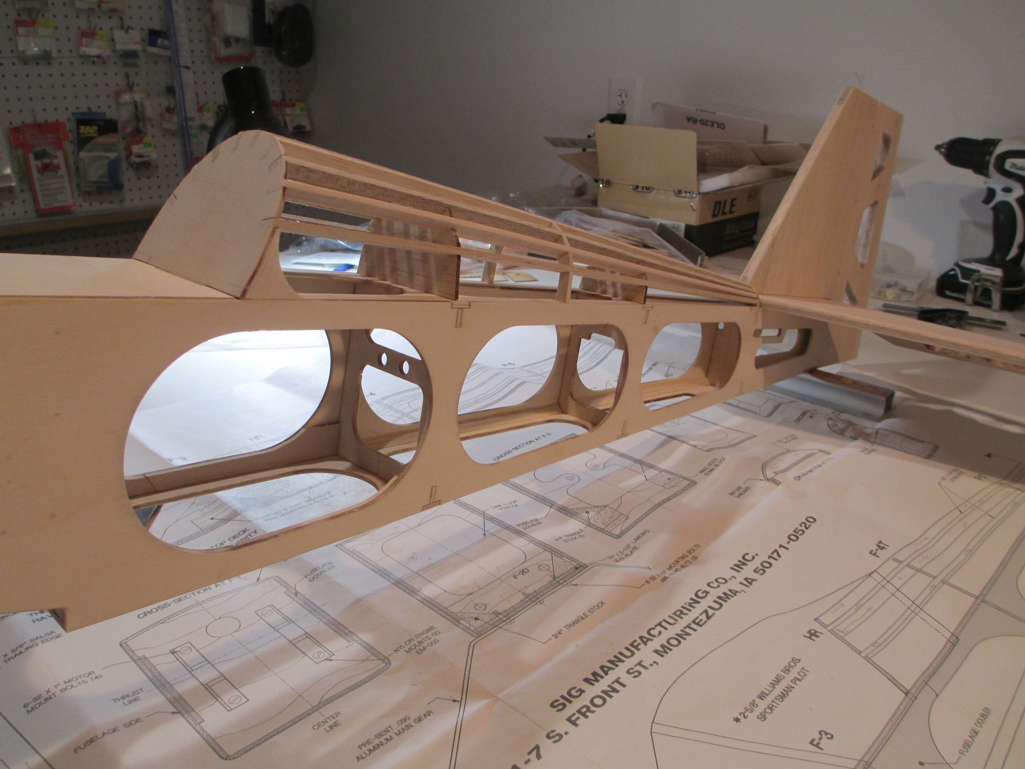
The tail will not be epoxied into position until AFTER I cover each component separately.
Nothing has been sanded or rounded over yet, so it still looks "chunky".
I like the proportions of the rudder. Now that I have the tail in place, I can now figure out where and how I'll position my servos. I don't think that I mentioned it before, but I will be installing a pull-pull system for the rudder...
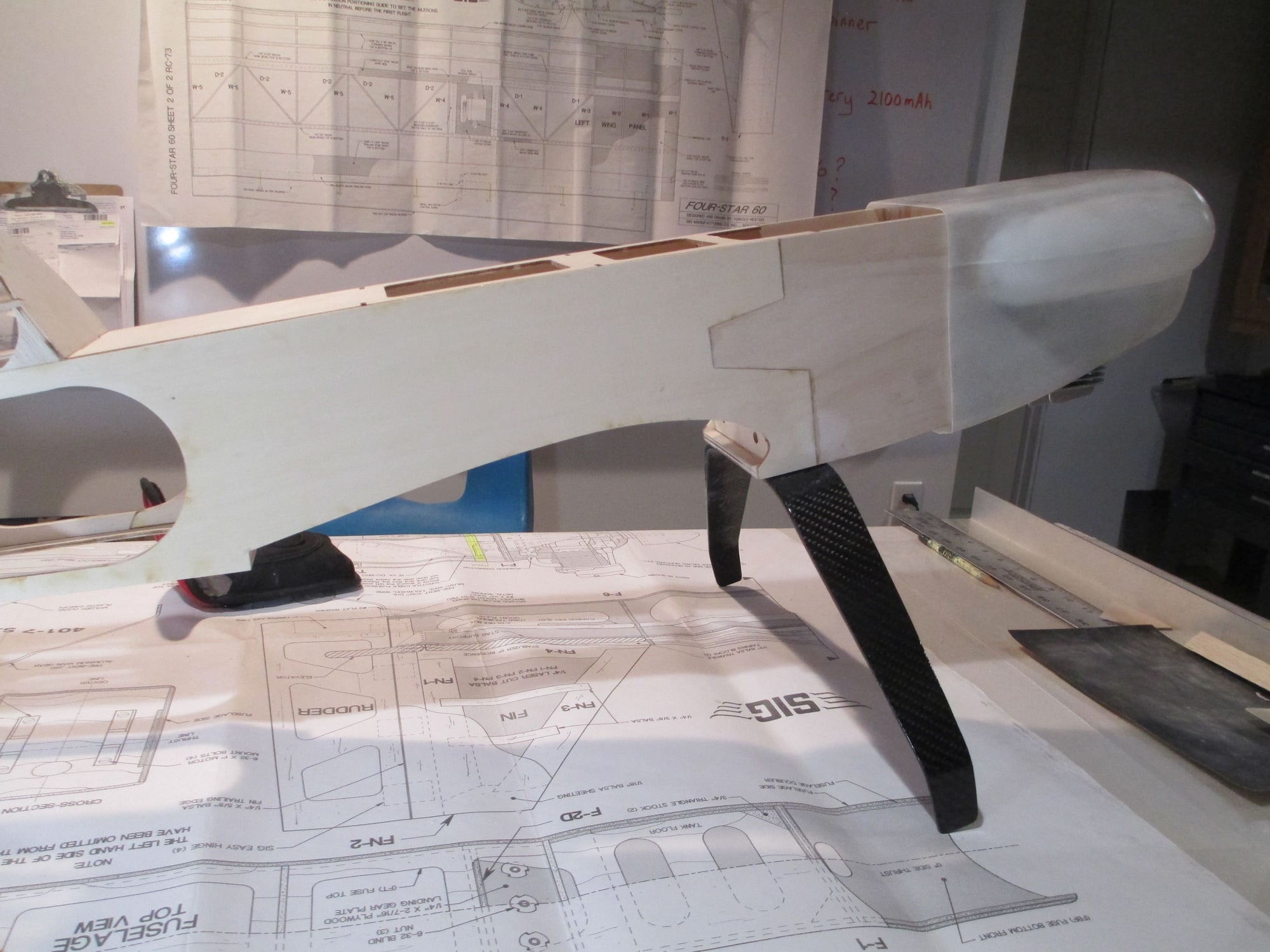
I have been anxious to see how the cowl would fit on the nose.
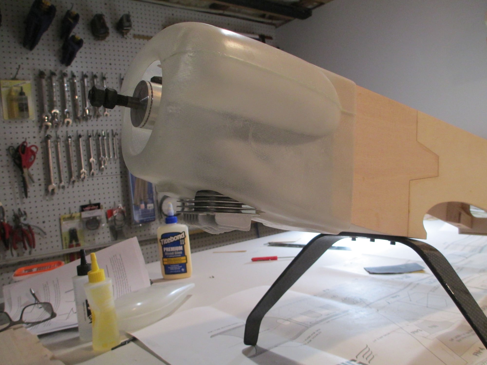
This is just roughed in and by no means final fit yet, but it's enough for me to know that the engine's prop shaft is where it's supposed to be.
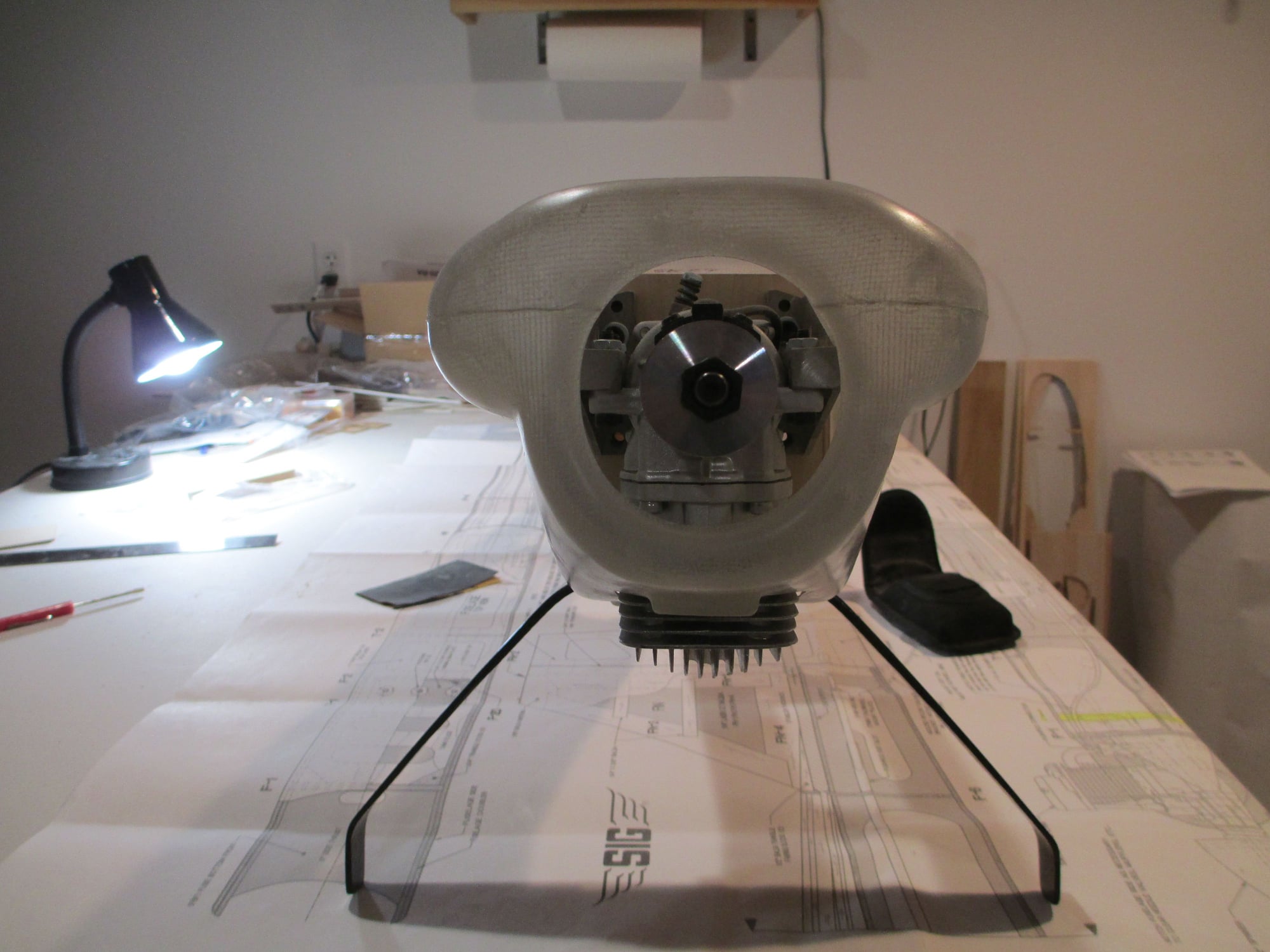
I like how the DLE-20 protrudes from the bottom of the cowl. Should work great for engine cooling...
Last edited by VincentJ; 04-18-2019 at 06:08 PM.
04-19-2019, 03:43 PM
#119
Thread Starter
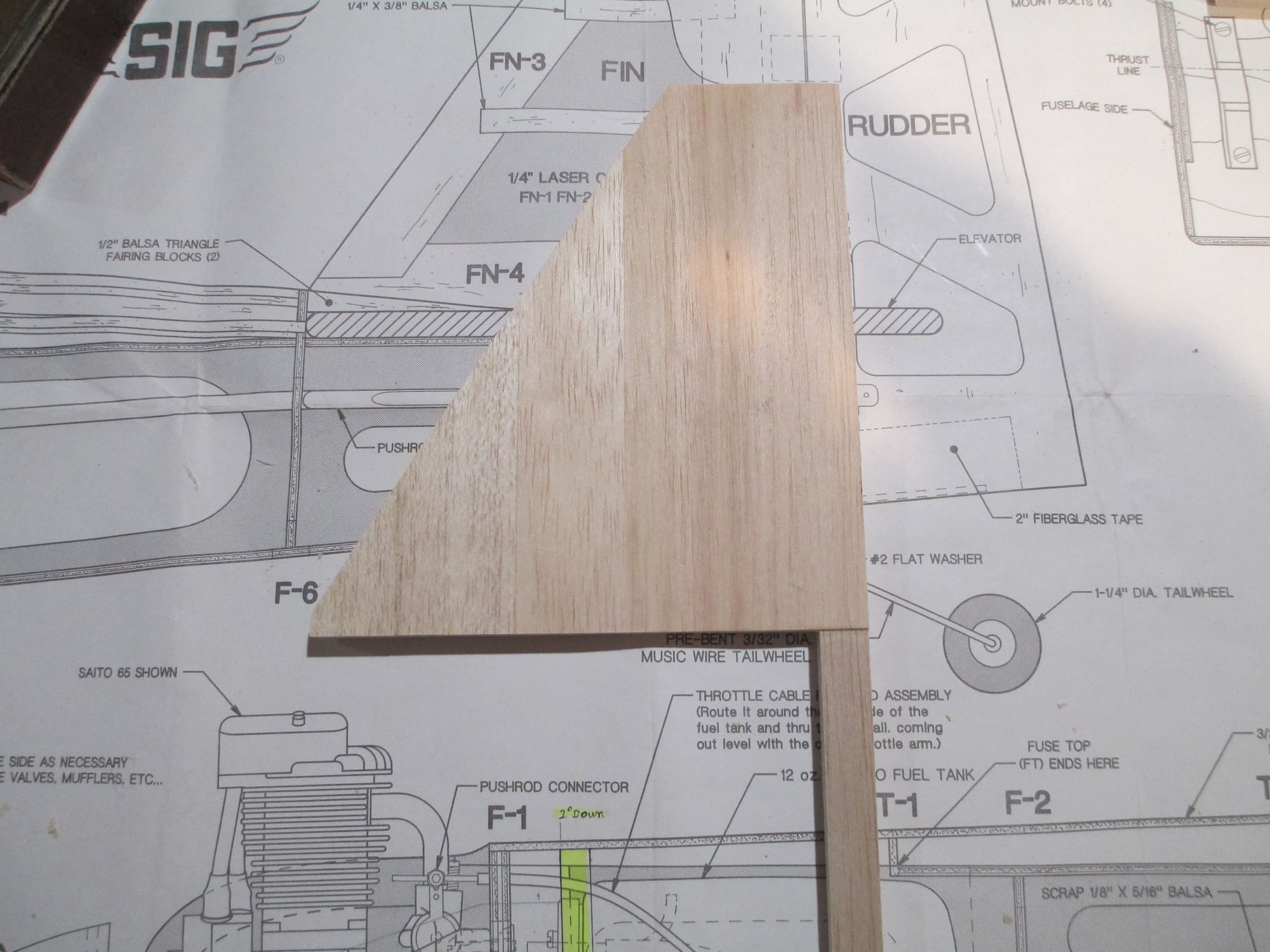
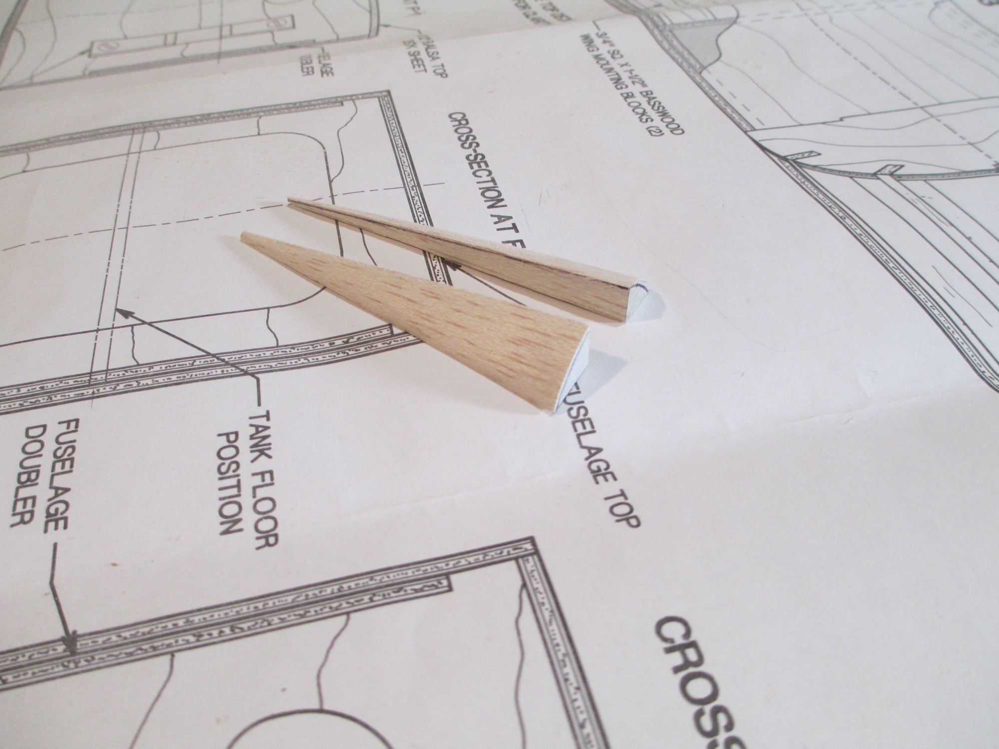
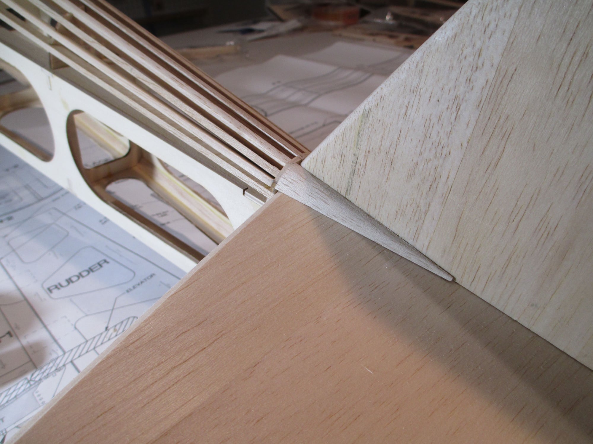
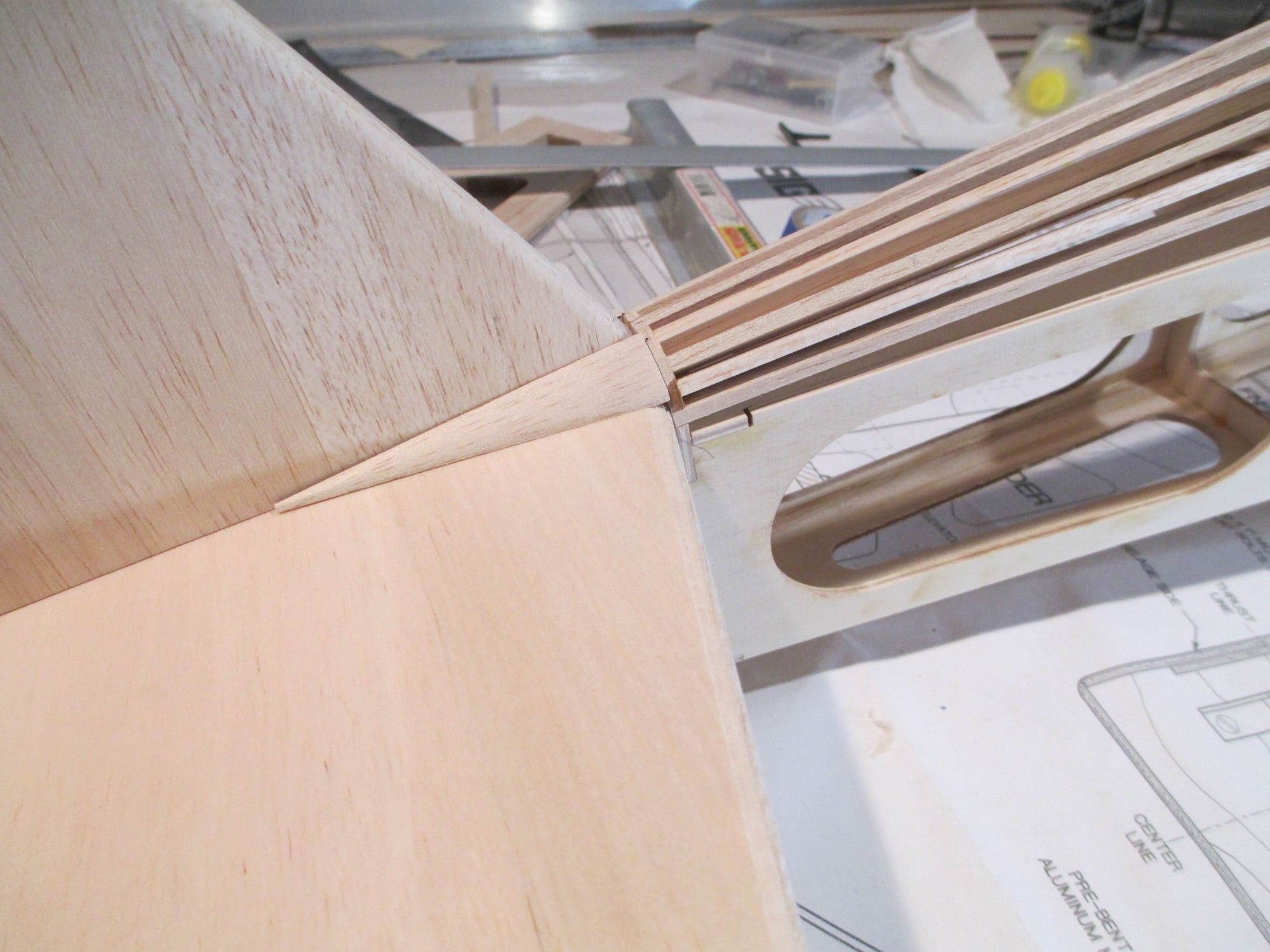
Tonight I decided to carve the two transition tail cones. I started with two three inch long, 3/4" tri-stock pieces. I traced the outline on the front.

It wasn't hard to carve them, but it was hard to hold them as them are quite small...
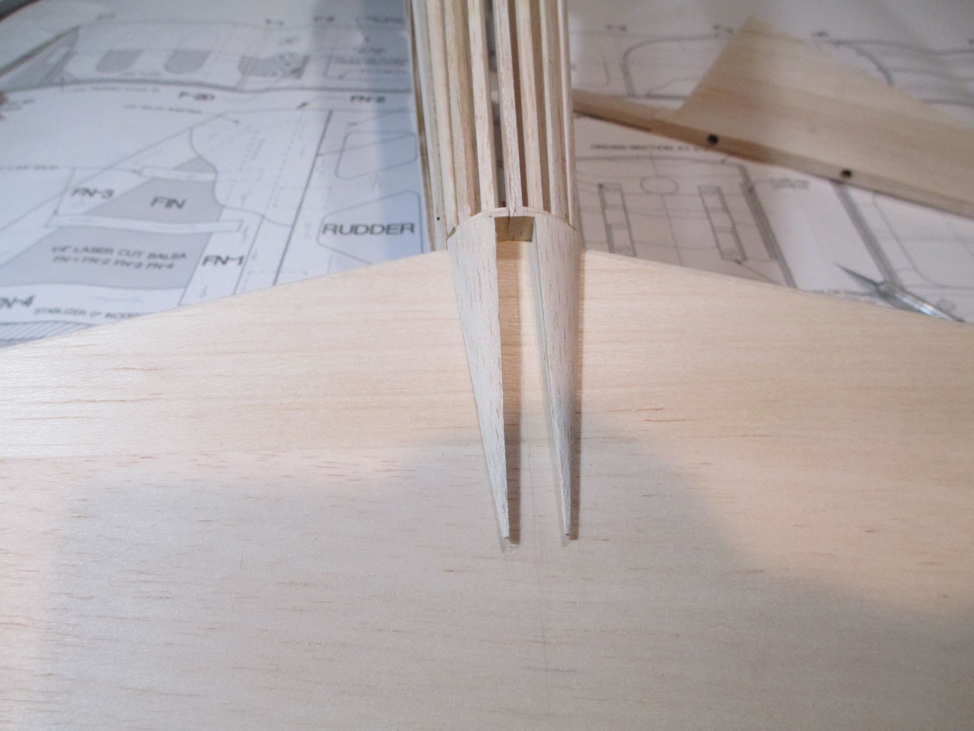
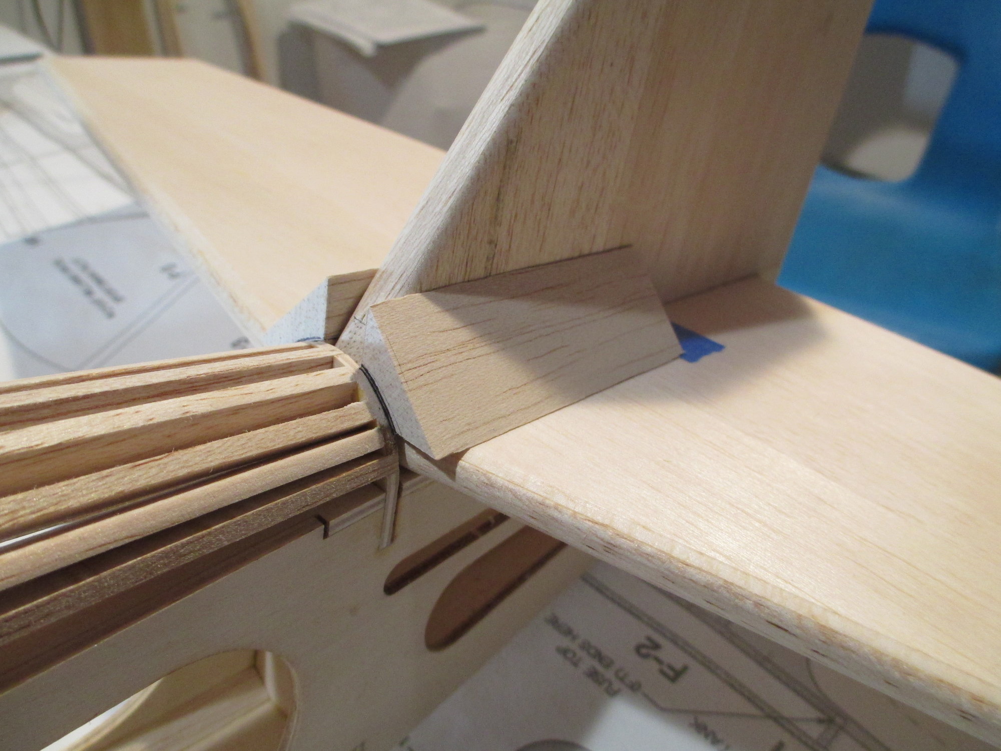
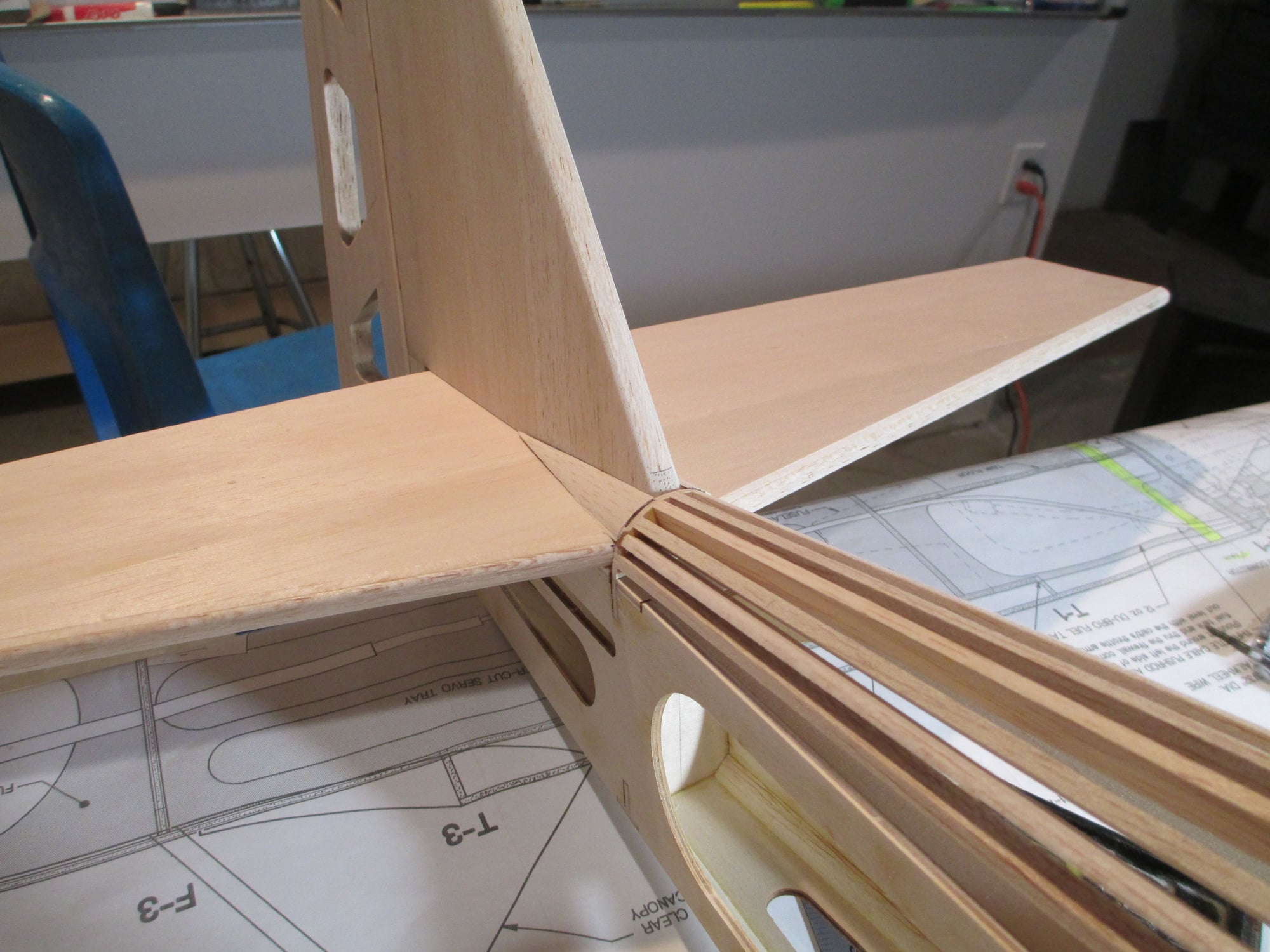
Once I got them pretty close I glued the front of the cones only to the fuselage. The horizontal stabilizer is in place to make sure that the cones are at the right height.
I think with some minor sanding they should be good enough...
 04-20-2019, 04:16 AM
#120
Thread Starter
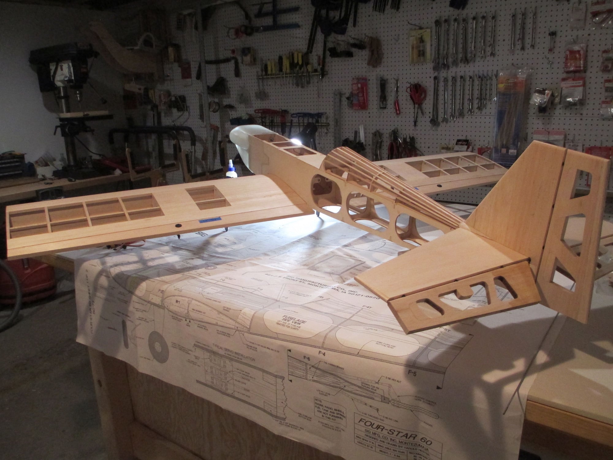
My good friend Bob has returned home from his Floridian hibernation and wanted to come over and see the progress of my Four Star. I assembled the plane for his inspection and I thought you may also want to see a couple of shots of it as well...
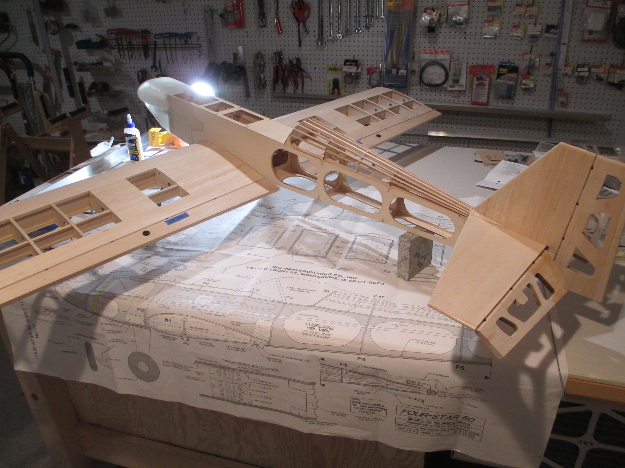
Tons of sanding and final fitment still left to do...
Tons of sanding and final fitment still left to do...
04-20-2019, 01:31 PM
#121
Thread Starter
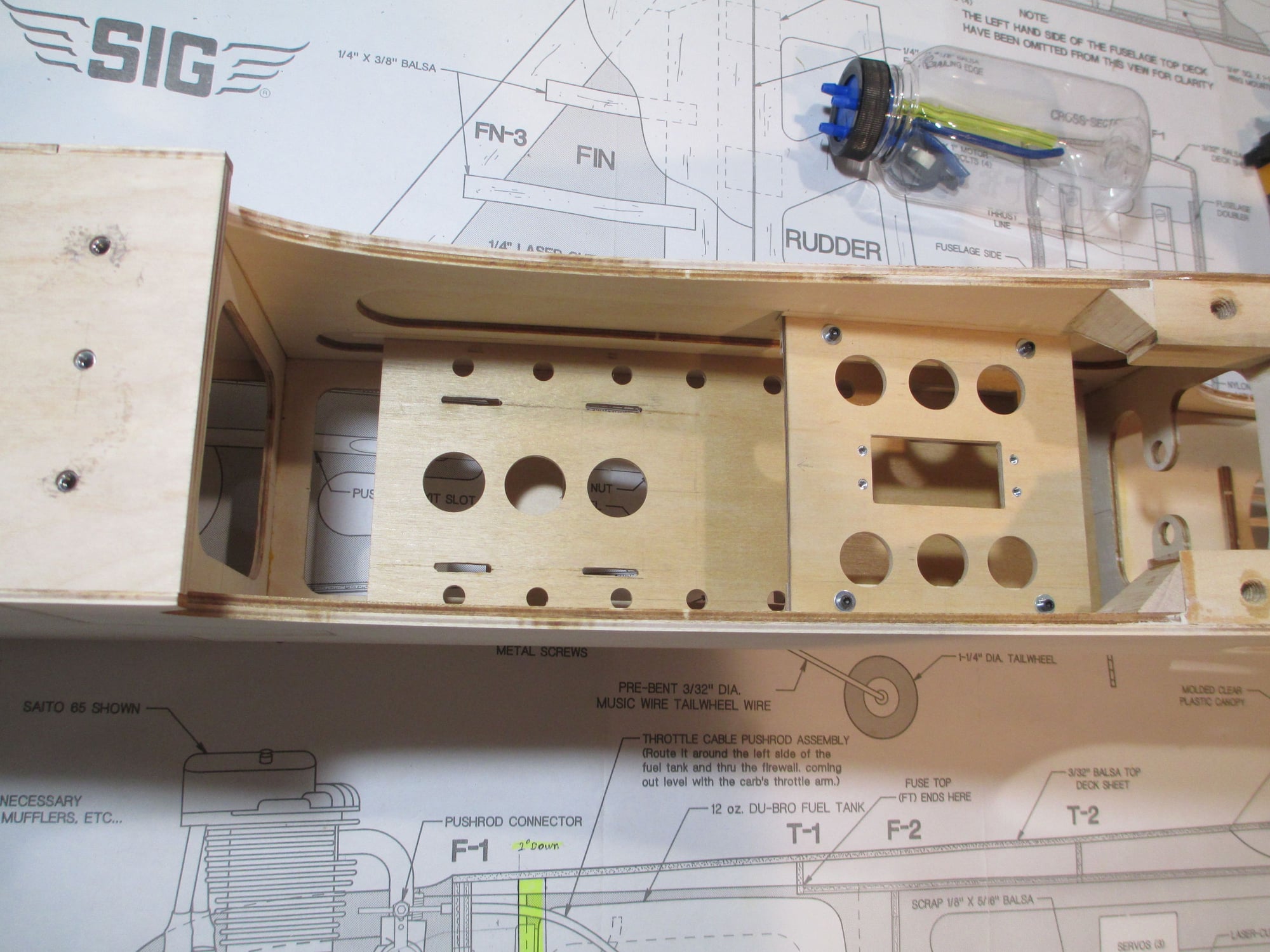
I spent a lot of time deciding the best place for all of the electronics,battery, etc. It can be a daunting task, but I'm always up for the challenge. I try to think about where the best location is based on its doing its job most efficiently. Secondly, I think about is the ability for that component to be removed should it need to be serviced in the future. The final decision is a compromise of both factors...
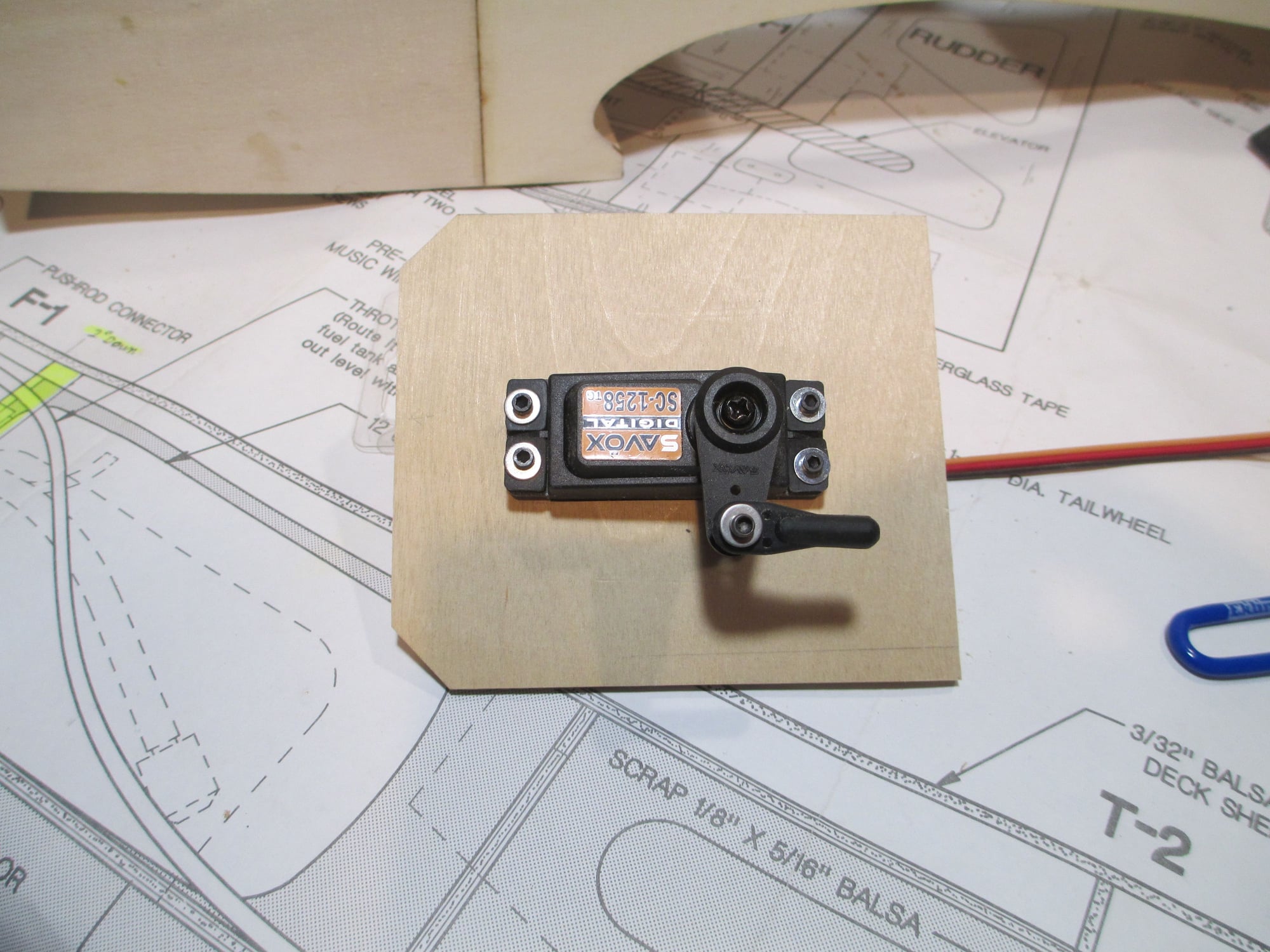
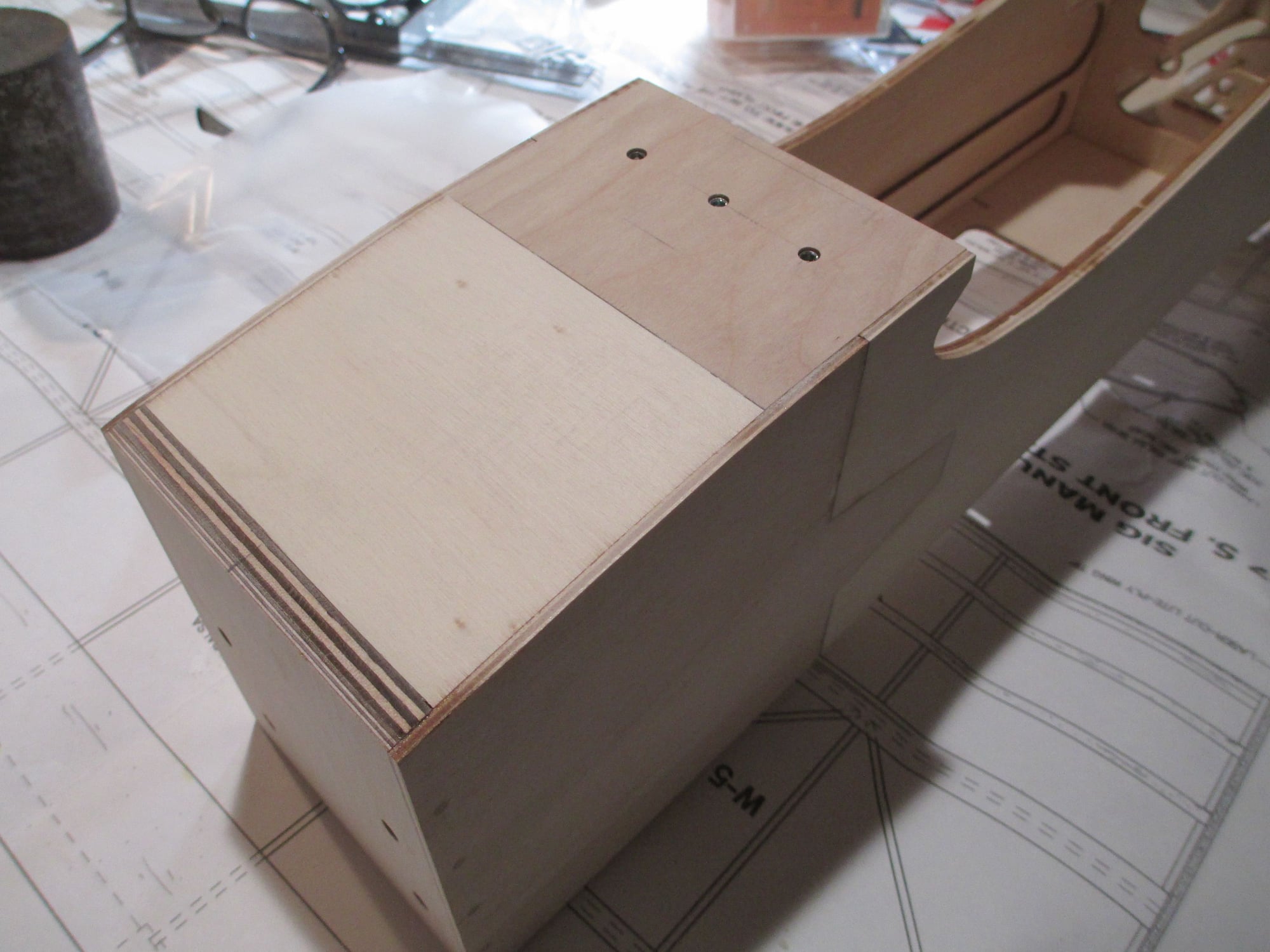
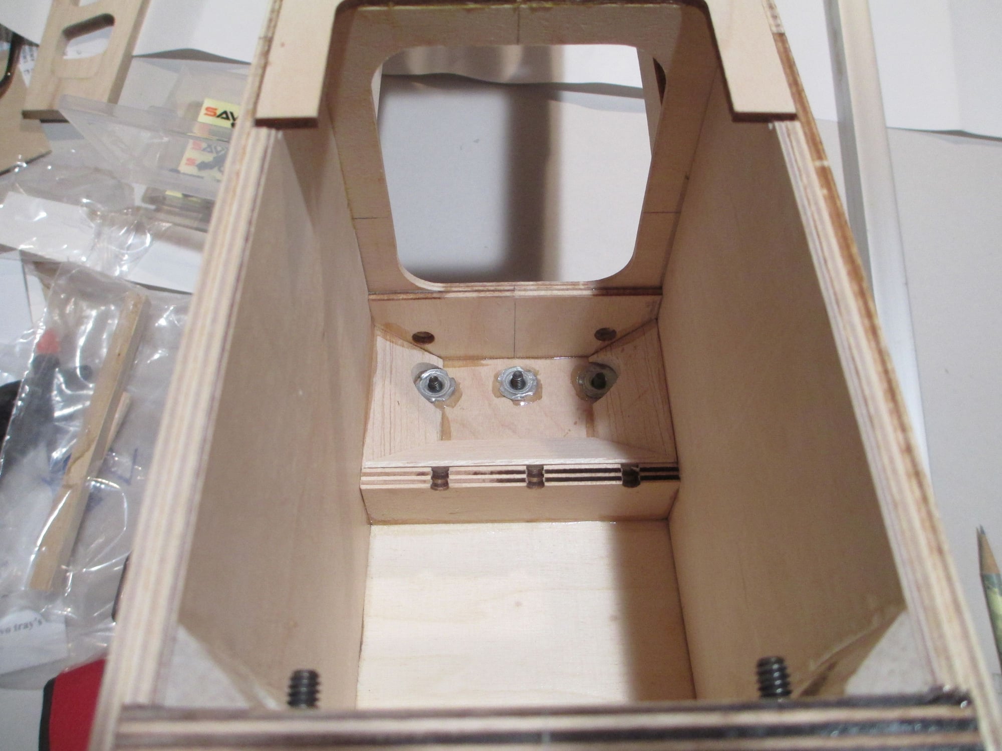
After deciding on where to place the throttle servo, a mounting plate was made from 1/8" birch plywood. I like to mount servos using four 2-56 x 1/2" cap head bolts. I'm not fond of threading screws into a hardwood rail as I see most do.
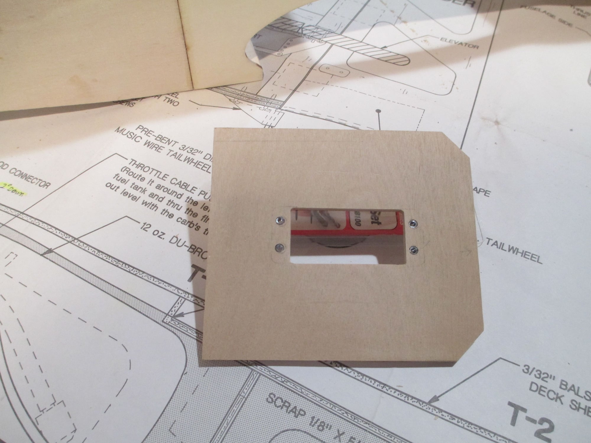
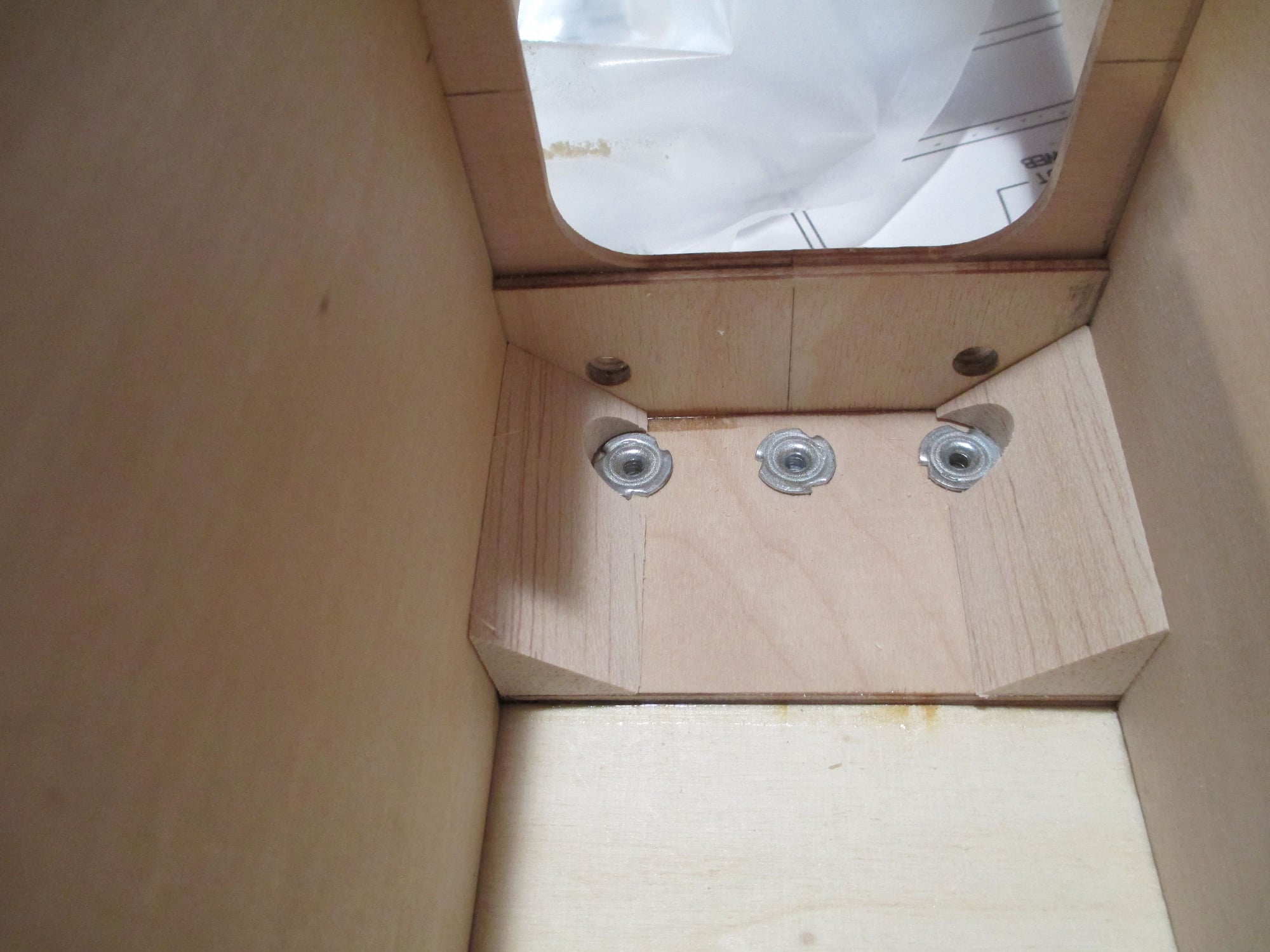
With the servo removed from its mount, you can see the top of the 2-56 blind nuts.
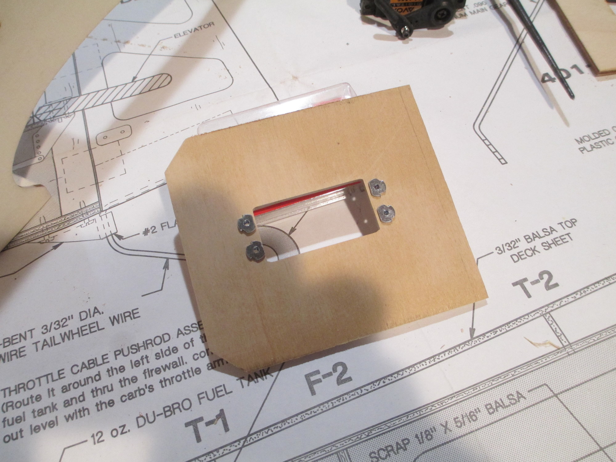
Bottom view of the blind nuts. these will get a dab of epoxy to ensure that they don't fall out of place.
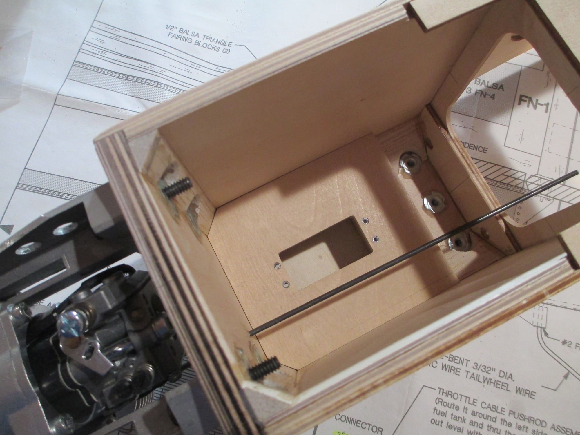
The plywood plate will be removable. The 4-40 rod shown is temporarily threaded into the throttle arm on the engine. The rod gave me the exact position of the throttle placement.
After deciding on where to place the throttle servo, a mounting plate was made from 1/8" birch plywood. I like to mount servos using four 2-56 x 1/2" cap head bolts. I'm not fond of threading screws into a hardwood rail as I see most do.
With the servo removed from its mount, you can see the top of the 2-56 blind nuts.
Bottom view of the blind nuts. these will get a dab of epoxy to ensure that they don't fall out of place.
The plywood plate will be removable. The 4-40 rod shown is temporarily threaded into the throttle arm on the engine. The rod gave me the exact position of the throttle placement.
Last edited by VincentJ; 04-20-2019 at 01:46 PM.
04-22-2019, 01:33 PM
#122
Thread Starter
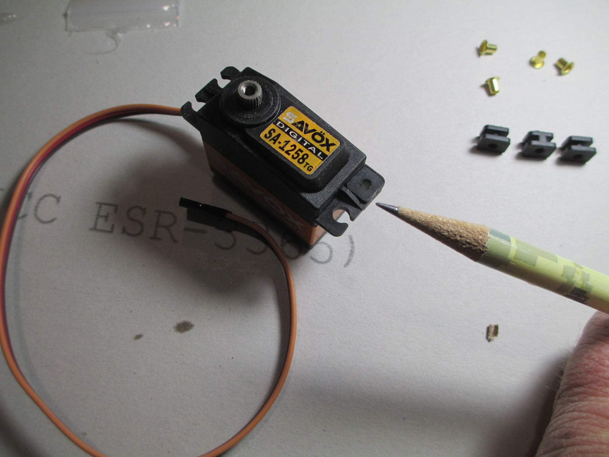
Servo prep basics. Here are a few tips to help make sure that you assemble your servos properly.
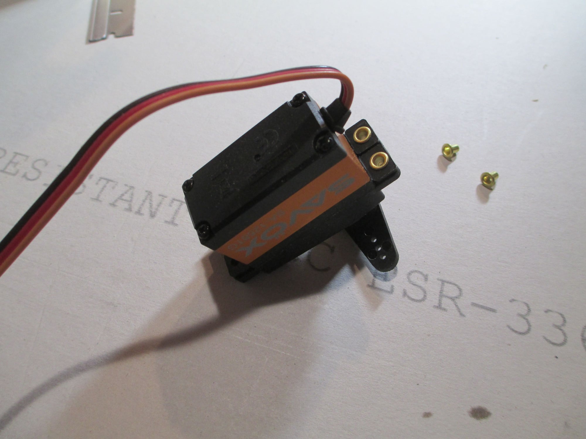
Have you ever had trouble inserting brass eyelets into the rubber servo grommets?
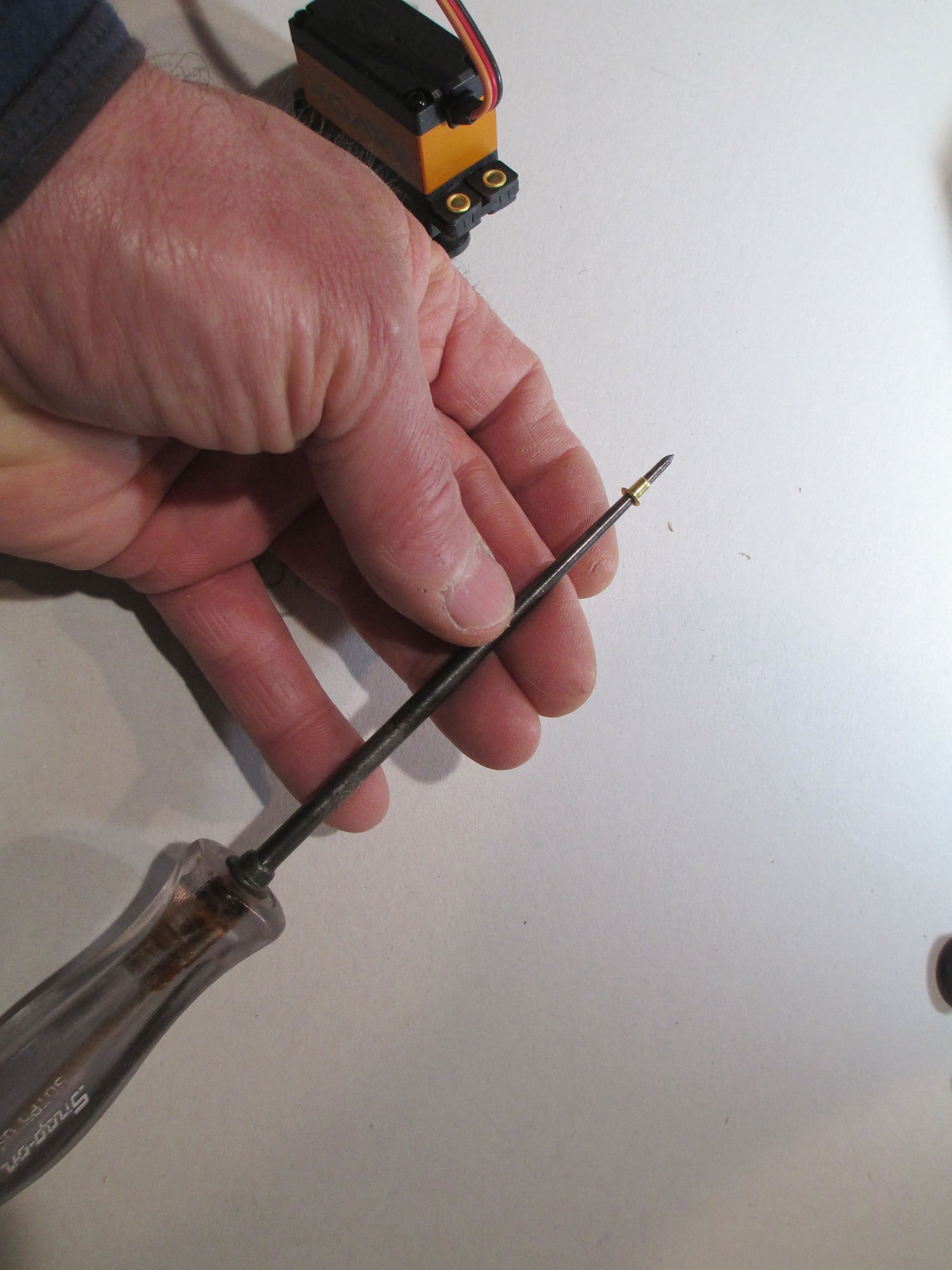
Here's an easy way to accomplish this task. Take the eyelet and slip it over the pointed end of an awl.
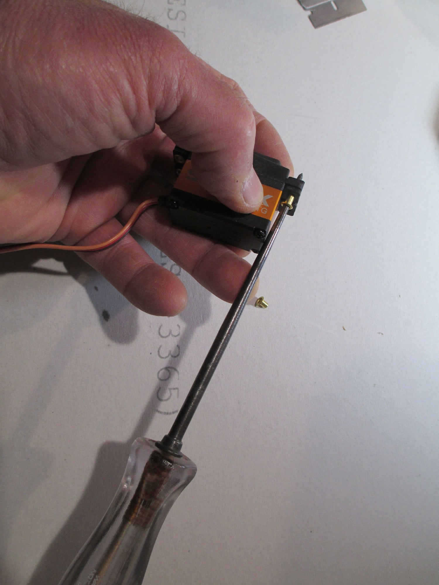
Then begin to press the eyelet into the rubber grommet...
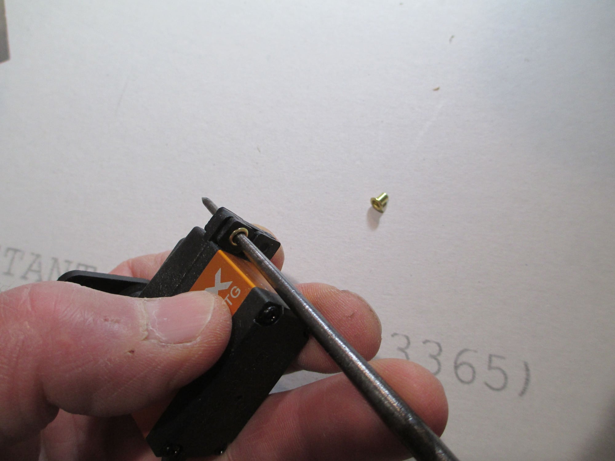
Until it's seated, then just pull out the awl. You're done!
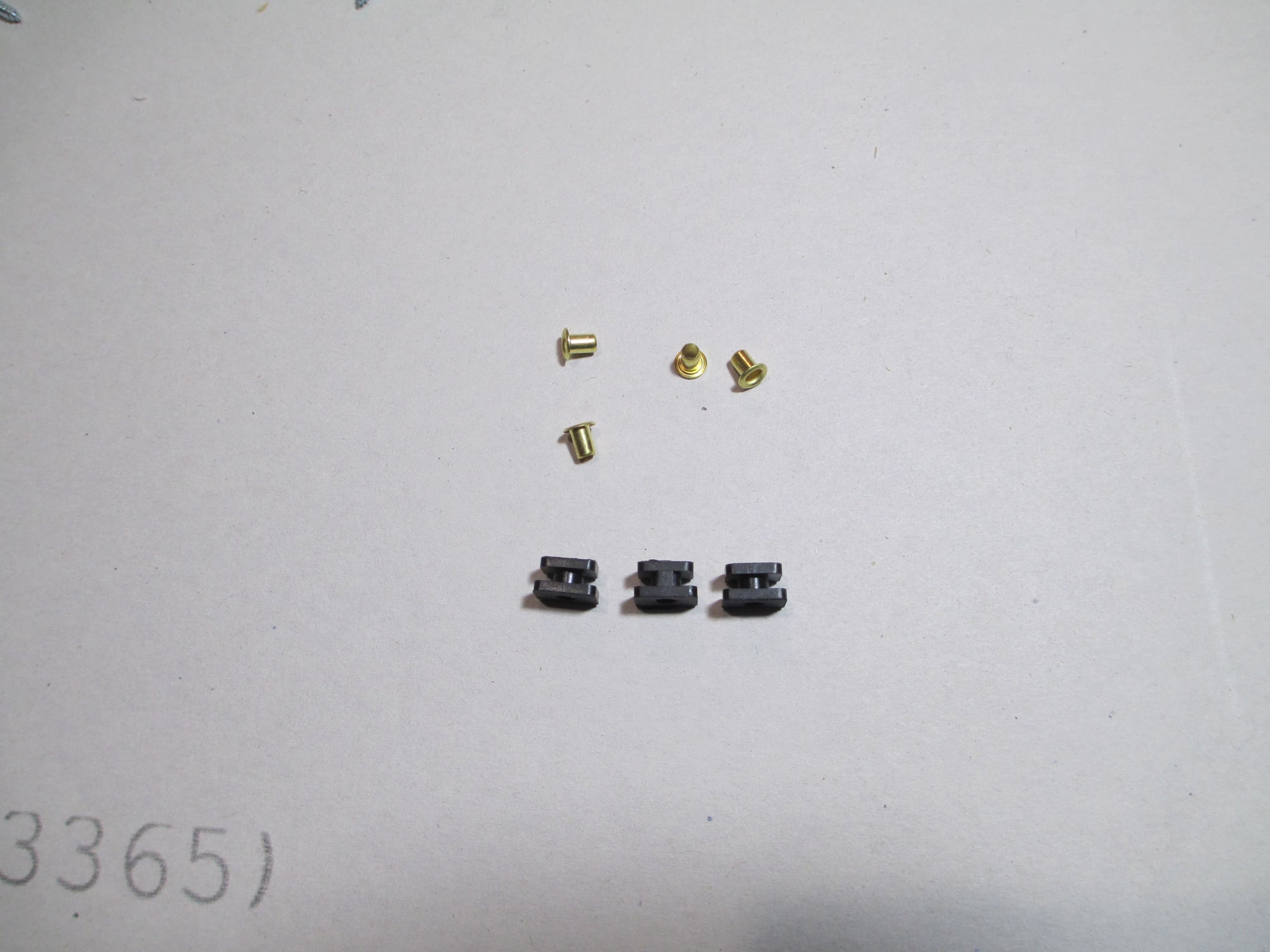
On the subject of rubber grommets, careful attention must be given in making sure the grommets are installed correctly. It's possible that you've never noticed that there is a size difference between the top and bottom portion of the grommet. The top is slightly narrower than the bottom.
The reason is because of this small divider. It's easy to accidentally slip them on upside down...
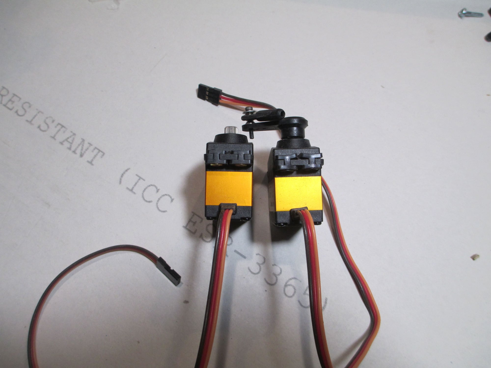
The servo on the left has the grommets installed correctly, while the one on the right has the grommets installed upside down.
Have you ever had trouble inserting brass eyelets into the rubber servo grommets?
Here's an easy way to accomplish this task. Take the eyelet and slip it over the pointed end of an awl.
Then begin to press the eyelet into the rubber grommet...
Until it's seated, then just pull out the awl. You're done!
On the subject of rubber grommets, careful attention must be given in making sure the grommets are installed correctly. It's possible that you've never noticed that there is a size difference between the top and bottom portion of the grommet. The top is slightly narrower than the bottom.
The reason is because of this small divider. It's easy to accidentally slip them on upside down...
The servo on the left has the grommets installed correctly, while the one on the right has the grommets installed upside down.
Last edited by VincentJ; 04-23-2019 at 03:27 AM.
04-23-2019, 07:52 AM
#123
Thread Starter
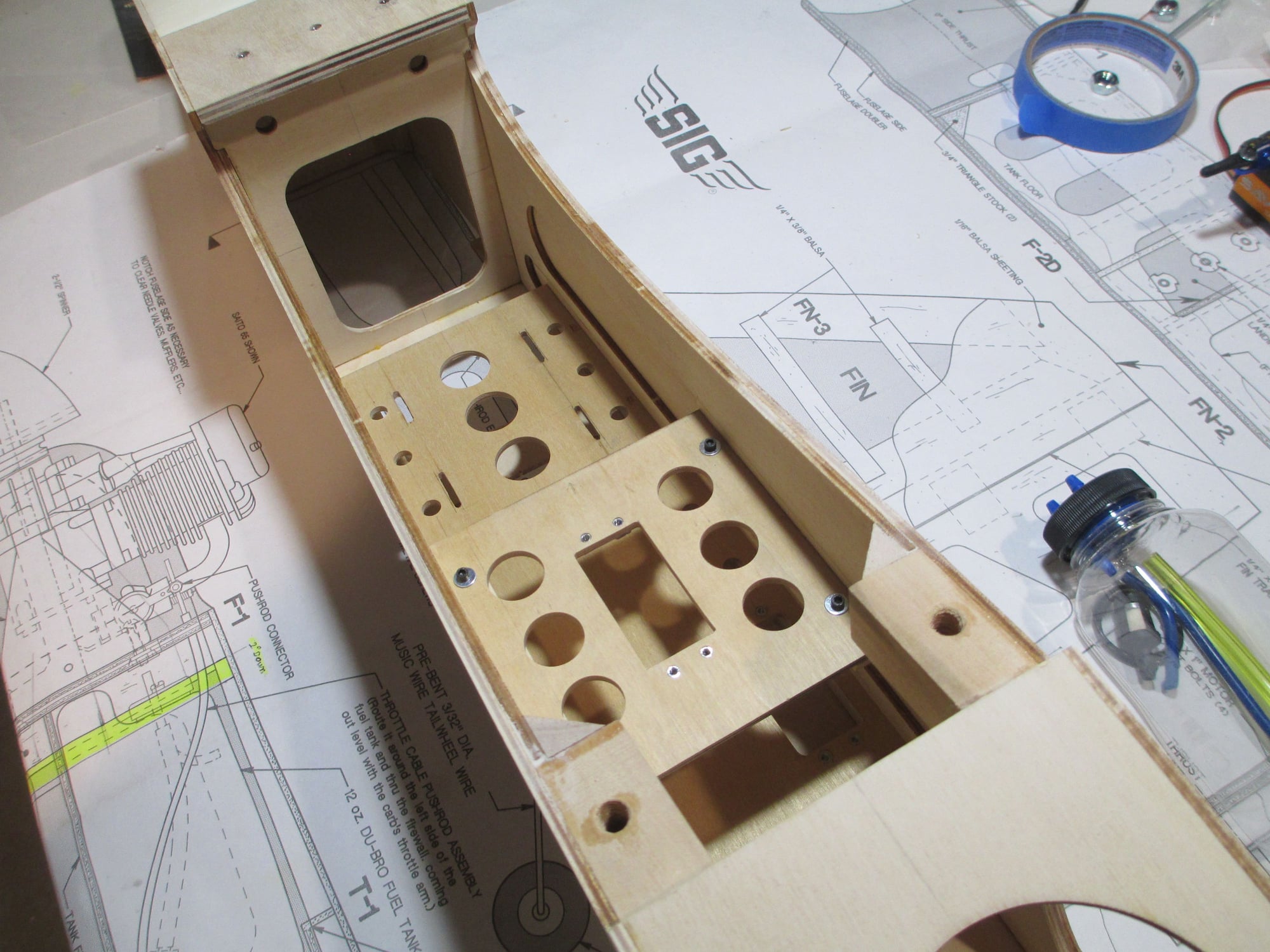
Here are a few shots of the two servo/mounting trays that I made. The upper tray is epoxied into place, while the lower tray is removable. Four 2-56 cap head screws hold the lower tray into place which will house the pull-pull servo on the rudder. The upper tray holds the elevator servo, gas tank as well as the rest of the electronics.
04-23-2019, 12:42 PM
#124
Junior Member
Join Date: Apr 2019
Posts: 2
Likes: 0
Received 0 Likes
on
0 Posts
Vince
I am following along as you build...but for a somewhat different reason... I am refurbishing a BTE VEnture 60 and am quite interested in the cowl you have chosen. As you likely know, both planes are derivatives of the 4*40 Bruce Tharpe designed while he worked at Sig.The two planes are very close in size. I contacted Sig and was given the firewall dimensions for the 4*60. The 4*60 firewall is 3/16 inch wider and 5/16 inch taller than the Venture at their respective firewalls. The firewall to spinner backplate dimension on the Venture is 5 1/8 inches...it appears that the 4*60 arf cowl requires a 5 9/16 inch dimension for firewall to spinner backplate spacing...sorry for the long winded preamble
I also emailed with Fiberglas Specialties.. they told me they don’t have a cowl that would work...but then I saw yours...and hope returned...I am going to invert my engine as well and loved the look of your installation...which cowl did you purchase from FS?...how long is the cowl?...what firewall to spinner backplate spacing are you seeing with your engine...it appears that there is a fair amount of taper from front to back...that taper may be enough to make the cowl a possibility...any help you could provide would be so appreciated...
Regards
Rick
04-24-2019, 02:06 AM
#125
Thread Starter
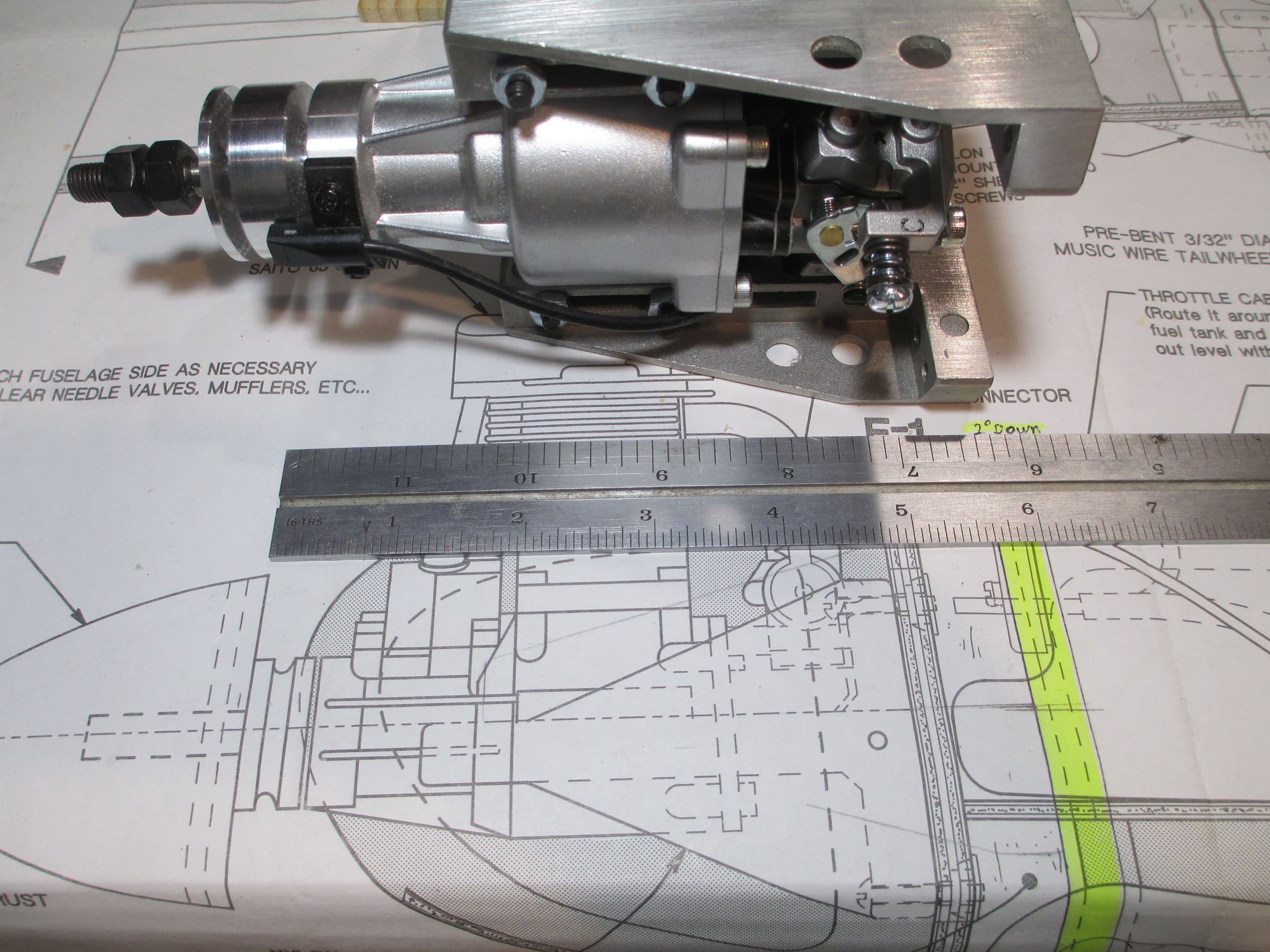
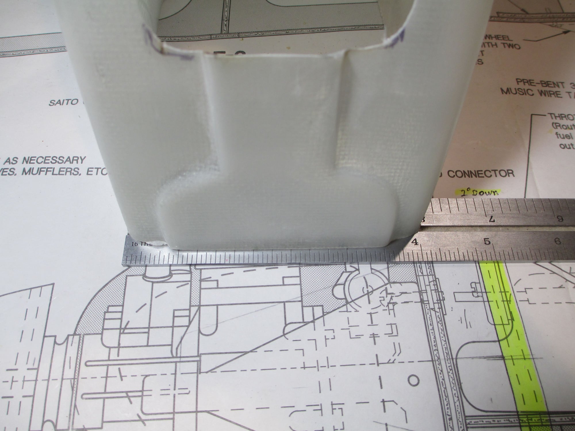
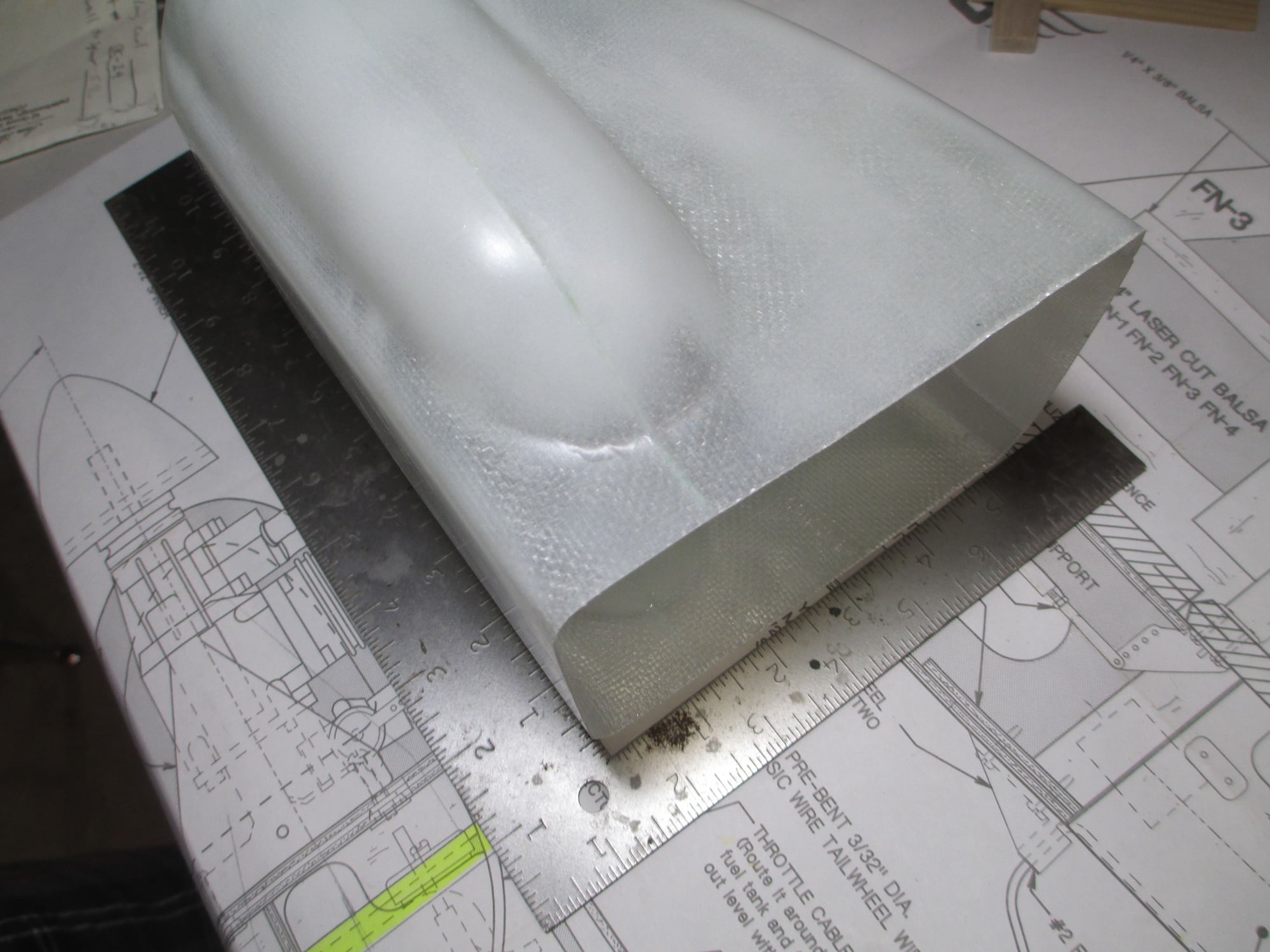
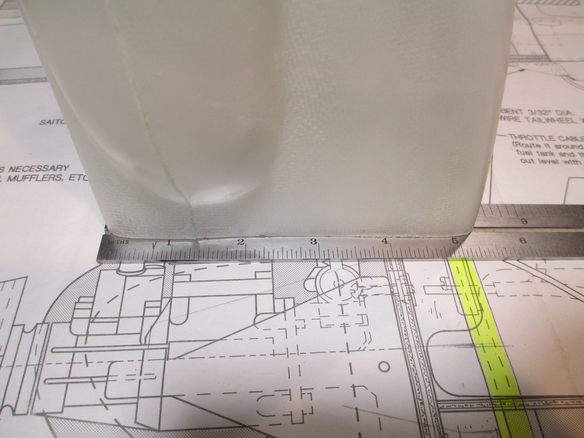
Hope these pictures are of some help to you Rick. I ordered the cowl as you know from Fiberglass Specialties.
The part # for the cowl is SK-29.
The length of the cowl is 6-3/4".
Firewall to spinner length is 5-11/16"
l
The part # for the cowl is SK-29.
The length of the cowl is 6-3/4".
Firewall to spinner length is 5-11/16"
l