


Super Kaos from Lazerworks Short Kit.
 05-18-2019, 08:24 AM
#26

Thread Starter

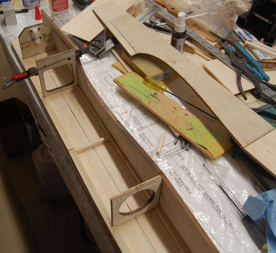
Stepping sideways over to the fuselage. The fuselage will be needed when it comes time to mark out and drill the holes in the leading edge for the dowels in the leading edge of the wing. I got a little way into the fuselage construction before I realized I hadn't taken a photo of the top deck. It is really pretty simple. The top deck is a four inch wide sheet of 3/16" balsa. Having a straight midline drawn down the center of the sheet helps with alignment. You can see in the photo where I redrew my line to get it straight. At this point you can start marking the location of the firewall and the formers. The plans show a 3/8 x 5/8 longeron that runs most of the length of the fuselage. The plans show it as having an odd polygon shape that was probably included in the kit. Leaving this piece in its rectangular cross section doesn't impact the construction of the kit. I suppose you could save a few grams by shaving it to the shape shown but I doubt it would be enough to make a difference. The fit of this longeron is important. It forms the upper corners of the fuselage and provides the material that is carved and sanded to give the rounded shape. The position of the longeron at the aft end of the fuselage is very important as it sets the location of the leading edge of the horizontal tail. At the front it butts against a sheet of 3/8 balsa that forms to top of the engine cowl.
The formers sit on top of 1/4 x 3/8 cross braces. You can see on the photo where I have marked some of the measurements for placing the braces. I wouldn't rely on those numbers for your own plane as your plans may be more or less accurate/consistent than my copy. I only mention this because this is a step in construction that will have a lot to do with how straight and symmetrical your airplane turns out. I've seen some pretty lumpy, lopsided airplanes that could eventually be trimmed to fly, but for aerobatics, symmetry is your friend. The firewall and formers are all glued perpendicular to the top deck and square to the centerline. If you look at the starboard side of the fuselage you can see a plywood doubler glued to the side of the fuselage. This is an addition that comes with the short kit and it is not shown on the plans. If you are building strictly according to the plans you wont be using it. In my case I am using a plastic engine mount rather than the hardwood beam mounts as shown in the plans. If I had gone route, Eddie at Lazer Works would have supplied me with the hardwood. If you look at the firewall you can see that there are cuts for the beam mounts if you choose to use them. The choice of the plastic engine mount impacts some things that I will discuss a bit later. One thing that won't wait is down thrust. The beam mount provides 2 degrees of down thrust. If you are a really good carpenter you could build this into the firewall. I will be using shims with the engine and firewall to get the down thrust. This will be important later when you are carving the cowl to match the spinner.
The formers sit on top of 1/4 x 3/8 cross braces. You can see on the photo where I have marked some of the measurements for placing the braces. I wouldn't rely on those numbers for your own plane as your plans may be more or less accurate/consistent than my copy. I only mention this because this is a step in construction that will have a lot to do with how straight and symmetrical your airplane turns out. I've seen some pretty lumpy, lopsided airplanes that could eventually be trimmed to fly, but for aerobatics, symmetry is your friend. The firewall and formers are all glued perpendicular to the top deck and square to the centerline. If you look at the starboard side of the fuselage you can see a plywood doubler glued to the side of the fuselage. This is an addition that comes with the short kit and it is not shown on the plans. If you are building strictly according to the plans you wont be using it. In my case I am using a plastic engine mount rather than the hardwood beam mounts as shown in the plans. If I had gone route, Eddie at Lazer Works would have supplied me with the hardwood. If you look at the firewall you can see that there are cuts for the beam mounts if you choose to use them. The choice of the plastic engine mount impacts some things that I will discuss a bit later. One thing that won't wait is down thrust. The beam mount provides 2 degrees of down thrust. If you are a really good carpenter you could build this into the firewall. I will be using shims with the engine and firewall to get the down thrust. This will be important later when you are carving the cowl to match the spinner.
 05-19-2019, 08:13 AM
#28
Thread Starter
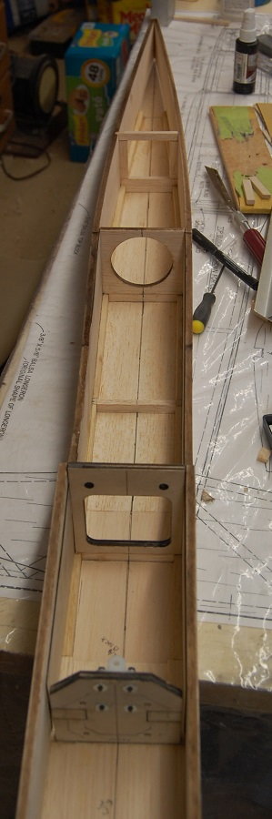
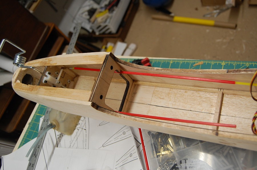
A view along the length of the fuselage so far. In an earlier post I mentioned the plywood fuselage doubler. This is an optional piece made of 1/32 ply. It adds strength to the fuselage, particularly in the absence of the hardwood engine mounts. It does create a small complication. The plans show that the fuselage sides are actually grooved to accept the F2 and F3 formers. As I've mentioned, I think that the RCM plans are a thinly edited version of the kit plans. I haven't seen an original Bridi Super Kaos kit but I would be willing to bet that there were slots milled into the fuselage sides for the formers. It would be a convenience for someone assembling a kit but it doesn't make that much sense for a plans built airplane. At any rate the doubler covers the area that would have been notched. Adding the ply and doing away with the notch adds about 3/32 inch to each side of the fuselage. Given that you are going to be removing a fair amount of material from the upper corners of he fuselage to achieve the rounded shape it probably wouldn't make that much difference if you use the F2 and F3 formers as cut. If you are building entirely to the plans with the hardwood engine mounts you will use the formers as cut. Since I am using the plywood doubler I decided to remove 3/32 from each side of the F2 and F3 formers to bring the fuselage sides in to the stock shape. looking aft yo can see the built up fram that forms F4 and the ends of the 3/8 x 5/8 longeron and the line that shows the leading edge of the horizontal tail. At this point the upper deck of the fuselage and the fuselage side form a slot that will accept the horizontal tail.
05-20-2019, 05:29 AM
#29
My Feedback: (2)
Hi Matt, check out this super Kaos for sale on the market place here:Bridi Super Kaos, OS FSR .61 w/Macs Pre-tuned pipe, retracts - RCU Forums. It has an OS 61FSR with tuned pipe.
TTL
Michael
TTL
Michael
05-20-2019, 07:32 AM
#30
Thread Starter
Hi Matt, check out this super Kaos for sale on the market place here:Bridi Super Kaos, OS FSR .61 w/Macs Pre-tuned pipe, retracts - RCU Forums. It has an OS 61FSR with tuned pipe.
TTL
Michael
TTL
Michael
05-21-2019, 08:25 AM
#32
Thread Starter
It wasn't so much the rain as it was the wind. As for teaching, I don't know what he would charge but Eddie has mentioned doing a class if we could get enough people in the club interested.
05-22-2019, 08:15 AM
#34
Thread Starter
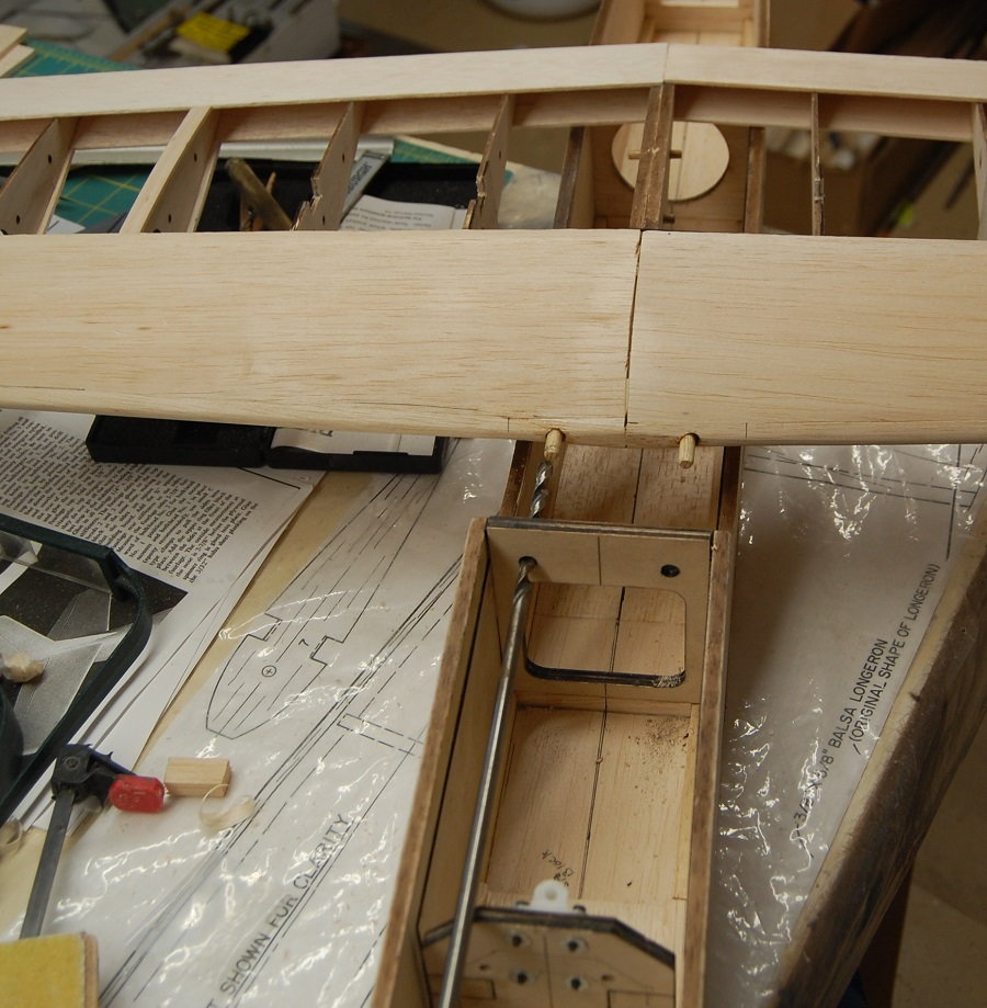
Hopping back over to the wing for a bit, while the F2 former is accessible I took the opportunity to drill the holes for the wing dowels. I used an extra long drill bit intended for running wiring in walls. It is a 1/4 inch bit available in the big box home improvement stores. The wing is located in the saddle using care to make sure it is square to the fuselage and in the desired position. The holes are then drilled using F2 as a guide. For best results do your best to keep the dowels parallel to each other.
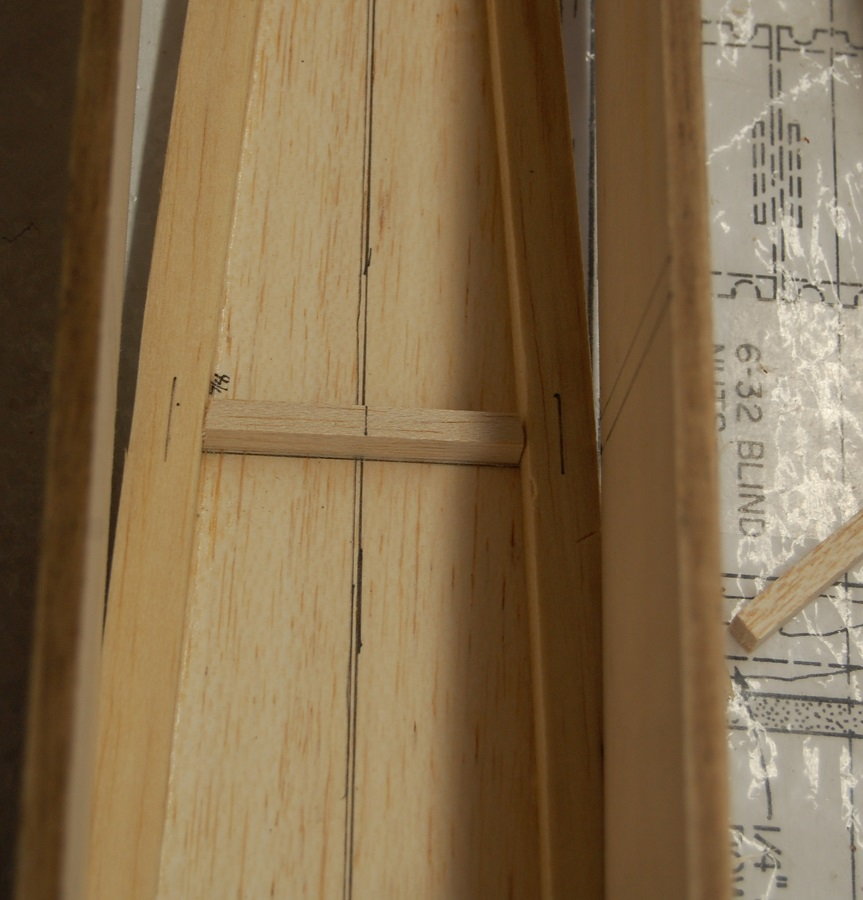
Sometimes I get on a roll with building and forget to take photos. I missed out on joining the wing halves. With this short kit the W1 root ribs are a thicker and provide material for sanding to fine tune the fit of the wing halves. The wings should be joined so that the upper surface is flat across the top of the spars. The root to tip taper will provide the small amount of dihedral shown on the plans. If the root ribs are glued square to the upper spar then little, if any, adjustment will be needed. Although I did not use a wing jig in construction the holes provided in the ribs are handy. If the wing is straight you will be able to look through the jig holes down the length of the wing from root to tip. The other convenience of the jig holes is that you can insert a bit of dowel in the holes as alignment pins when you glue the wing halves together. In the photo below you can also see the addition of a bit of carbon fiber. This is just a bit of Dave Brown carbon fiber tape that I used to tie the wing halves together. It's not in the plans but extra strength for very little extra weight. The back halves of the wing dowels are anchored in plywood plates glued to the back of the spars. I used epoxy with a fillet of thick CA. The plans mention "false ribs" that apparently fit on the top and bottom of the wing dowels but the false ribs themselves are not shown on the plans. Assuming that the purpose of these ribs was to strengthen the wing dowels I just added some 3/16 inch stock to the top and bottom of each dowel. This is due to an omission in the RCM plans. After I got done with this part of the wing I went back and looked at several of the sets of Kaos plans available on the internet. The RCM Super Kaos 40 plans show the false ribs but the 60 size plans do not. All that said, I think with the 3/16 inch stock added to the top and bottom of the dowels they will be sufficiently rigid. My plates anchoring the rear of the wing dowels are a little larger than shown on the plans but I wanted to tie them to the root ribs.
Sometimes I get on a roll with building and forget to take photos. I missed out on joining the wing halves. With this short kit the W1 root ribs are a thicker and provide material for sanding to fine tune the fit of the wing halves. The wings should be joined so that the upper surface is flat across the top of the spars. The root to tip taper will provide the small amount of dihedral shown on the plans. If the root ribs are glued square to the upper spar then little, if any, adjustment will be needed. Although I did not use a wing jig in construction the holes provided in the ribs are handy. If the wing is straight you will be able to look through the jig holes down the length of the wing from root to tip. The other convenience of the jig holes is that you can insert a bit of dowel in the holes as alignment pins when you glue the wing halves together. In the photo below you can also see the addition of a bit of carbon fiber. This is just a bit of Dave Brown carbon fiber tape that I used to tie the wing halves together. It's not in the plans but extra strength for very little extra weight. The back halves of the wing dowels are anchored in plywood plates glued to the back of the spars. I used epoxy with a fillet of thick CA. The plans mention "false ribs" that apparently fit on the top and bottom of the wing dowels but the false ribs themselves are not shown on the plans. Assuming that the purpose of these ribs was to strengthen the wing dowels I just added some 3/16 inch stock to the top and bottom of each dowel. This is due to an omission in the RCM plans. After I got done with this part of the wing I went back and looked at several of the sets of Kaos plans available on the internet. The RCM Super Kaos 40 plans show the false ribs but the 60 size plans do not. All that said, I think with the 3/16 inch stock added to the top and bottom of the dowels they will be sufficiently rigid. My plates anchoring the rear of the wing dowels are a little larger than shown on the plans but I wanted to tie them to the root ribs.
05-22-2019, 09:10 AM
#35
Well done Matt! Do yourself a favor, next time don't glue those wing dowels in quite yet. All they'll do is make it a pain to cover around them. Glue them in after you've finished covering the wing.
Last edited by VincentJ; 05-22-2019 at 10:21 AM.
05-22-2019, 07:03 PM
#36
Thread Starter
Hi Vincent, you aren't wrong. In this case there were some structural bits (false ribs) that presumably stiffen the dowels. I got ahead of myself on the photography and didn't get a picture of that part of the structure. I don't know a lot about the history of the Kaos line but the false ribs weren't present in the Kaos' predecessor the Sun Fli. the false ribs show up in the Kaos and Super Kaos but then there are at least three wing mounting schemes throughout the Kaos variants and their successors. Assuming good quality material in the dowels I'm not sure that the false ribs are really necessary. The only time I've ever had a dowel fail was in the process of cartwheeling or otherwise crashing a plane. Oh well, the reinforcements are there and they had to be installed before I buttoned up the wing. I agree with you. The fewer the bumps and knobs that you have to work around the easier the covering job will be. I've been following your 4 Star build and I have to say that I admire your technique.
05-23-2019, 02:21 PM
#37
Thread Starter
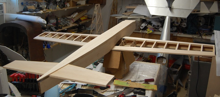
Putting the big pieces together for the first time. Lots of things to shape and button up. Most of the cap strips are on the wing but the center section hasn't been sheeted yet and there are no tips or servo mounts in the wings yet. Lots of carving and sanding ahead.
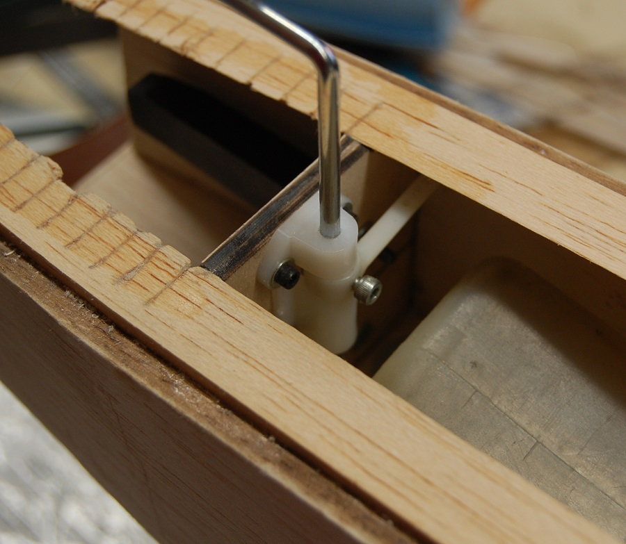
A quick look at the nose gear. Although this is as per the plans, it isn't the easiest in terms of eventual maintenance. If you were using the stock beam mounts it would probably be better to put the gear mount on the front side of the firewall. There are also engine mounts that have an integrated nose gear mount but I didn't have one on hand that would fit my engine and squeeze into the engine bay. All the same there is plenty of room in the fuel tank compartment. A twelve ounce tank s a good fit and it leaves space up front for the steering arm. I will probably end up putting in a hatch over the tank compartment. This seems to be a relatively common modification to the Super Kaos.
A quick look at the nose gear. Although this is as per the plans, it isn't the easiest in terms of eventual maintenance. If you were using the stock beam mounts it would probably be better to put the gear mount on the front side of the firewall. There are also engine mounts that have an integrated nose gear mount but I didn't have one on hand that would fit my engine and squeeze into the engine bay. All the same there is plenty of room in the fuel tank compartment. A twelve ounce tank s a good fit and it leaves space up front for the steering arm. I will probably end up putting in a hatch over the tank compartment. This seems to be a relatively common modification to the Super Kaos.
05-24-2019, 10:27 AM
#38
My Feedback: (2)
Hi Matt, this picture confused me a little as I wash looking in front of the nose gear block, it looks like there is a piece of metal stinking up and then it donned on me that was firewall. the multiple shades of black and grey threw me off. take care
Michael
Michael
05-25-2019, 08:17 AM
#39
Thread Starter
Hmm, the colors are probably just an artifact of the photo. The firewall is made of laminated plywood. The color is just a little leftover scorch from the laser cutting. My shop is lit with LED striplights. I have no idea what their color balance is. If I have something where the color is critical I take it outside to look at it in sunlight.
05-26-2019, 09:22 AM
#41
Thread Starter
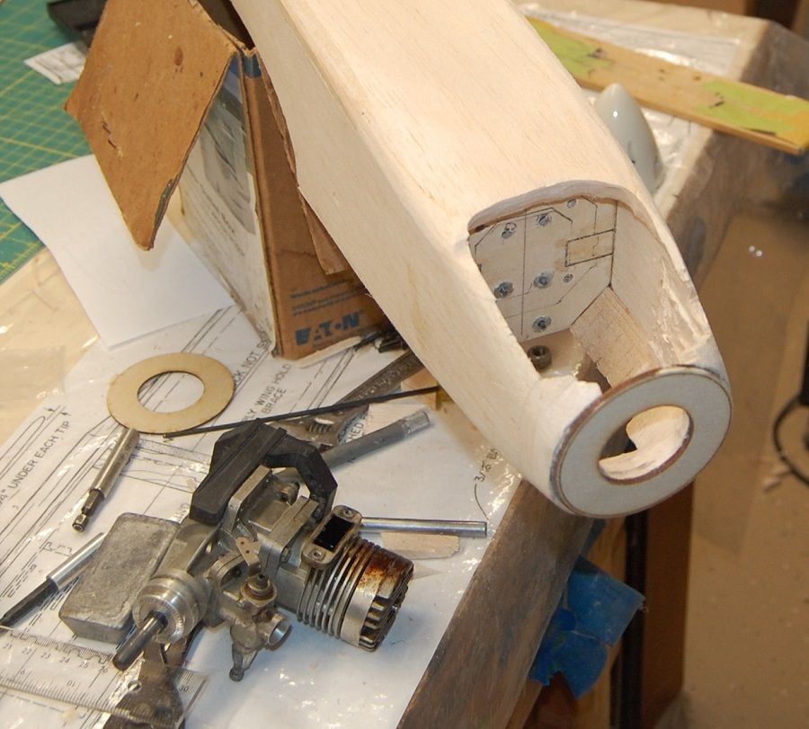
Shaping the nose. There are lots of airplanes that have an engine just hanging off of a firewall. The fly well but most of the time you wouldn't call them pretty. The carved nose is one of the things that makes for a good looking airplane, at least with the Super Kaos. At this point is is necessary to be able to mount up the engine.
The engine I am going to be using is a Fox Eagle .60 . This one needs to have the castor residue cleaned off of it but it is strong engine, barely out of its break-in period. The case on the Eagle series of engines is pretty large and takes up most of the room in the engine compartment. It also requires a little wider than usual engine mount. A smaller case .60 would probably give you a little more room. The SPA also allows you to run up to a .91 four-stroke. If running a four stroke you should probably plan for a little longer nose. If you choose to go electric it is possible to have a really slim nose. Again you may want to plan for a longer nose but more to address the balance than for the addition length of a four-stroke. The plans call for 2 degrees of down thrust. If you are using the built in hardwood engine bearers this is designed in but if you are using a plastic engine mount build the down thrust into the fire wall or plan to shim the engine or the mount to get the desired down thrust. The plans don't show any side thrust.
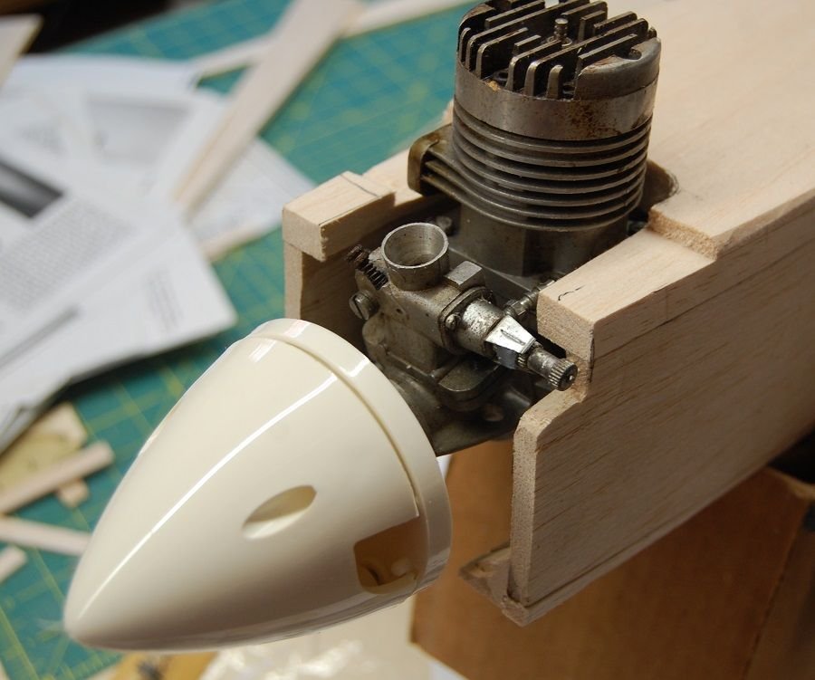
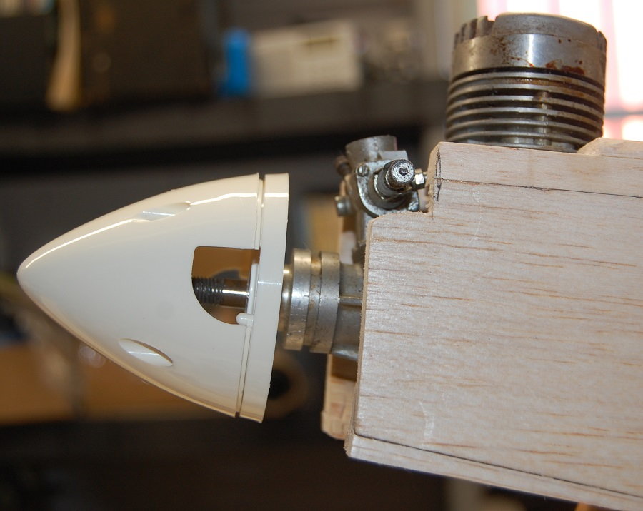
Being able to mount the engine in its desired position is important for lining up the plywood nose ring. Laser Works supplies a couple of plywood nose rings that are the diameter of the spinner called for on the plans. In this case 2 3/4 inches. I added about 5/8 of an inch to the nose to get to front of the engine and centered the ring on the snout of the engine. How much material you add will depend on the length of your engine. At this point it is a process of carve and sand away anything that doesn't look like a Super Kaos. It's a little crude at this point. You can also see the outlines where the plastic mount will go along with the cut marks where the beam mounts would be if you were using them.
With the engine and spinner in place you start to get a picture of how the shape of the nose will flow. Lots of sanding to do yet and I've only begun to shape the top of the fuselage.
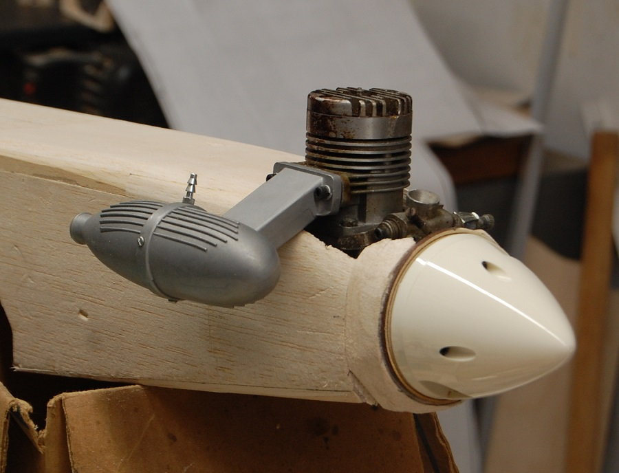
I haven't yet added the balsa block that will form the bottom of the fuel tank and engine compartments. Adding this component will do a lot to fill out the shape of the nose. Shaping the nose isn't difficult but it is time consuming. It isn't a scale model so getting a particular shape isn't critical. If it is symmetrical, smooth and reasonably streamlined it will work. Even a ham fisted individual such as my self can get something that is aesthetically pleasing if you take you time with it. This one is still rough but you can see the shape starting to come out.

The engine I am going to be using is a Fox Eagle .60 . This one needs to have the castor residue cleaned off of it but it is strong engine, barely out of its break-in period. The case on the Eagle series of engines is pretty large and takes up most of the room in the engine compartment. It also requires a little wider than usual engine mount. A smaller case .60 would probably give you a little more room. The SPA also allows you to run up to a .91 four-stroke. If running a four stroke you should probably plan for a little longer nose. If you choose to go electric it is possible to have a really slim nose. Again you may want to plan for a longer nose but more to address the balance than for the addition length of a four-stroke. The plans call for 2 degrees of down thrust. If you are using the built in hardwood engine bearers this is designed in but if you are using a plastic engine mount build the down thrust into the fire wall or plan to shim the engine or the mount to get the desired down thrust. The plans don't show any side thrust.
Being able to mount the engine in its desired position is important for lining up the plywood nose ring. Laser Works supplies a couple of plywood nose rings that are the diameter of the spinner called for on the plans. In this case 2 3/4 inches. I added about 5/8 of an inch to the nose to get to front of the engine and centered the ring on the snout of the engine. How much material you add will depend on the length of your engine. At this point it is a process of carve and sand away anything that doesn't look like a Super Kaos. It's a little crude at this point. You can also see the outlines where the plastic mount will go along with the cut marks where the beam mounts would be if you were using them.
With the engine and spinner in place you start to get a picture of how the shape of the nose will flow. Lots of sanding to do yet and I've only begun to shape the top of the fuselage.
I haven't yet added the balsa block that will form the bottom of the fuel tank and engine compartments. Adding this component will do a lot to fill out the shape of the nose. Shaping the nose isn't difficult but it is time consuming. It isn't a scale model so getting a particular shape isn't critical. If it is symmetrical, smooth and reasonably streamlined it will work. Even a ham fisted individual such as my self can get something that is aesthetically pleasing if you take you time with it. This one is still rough but you can see the shape starting to come out.
05-27-2019, 09:02 AM
#42
Thread Starter
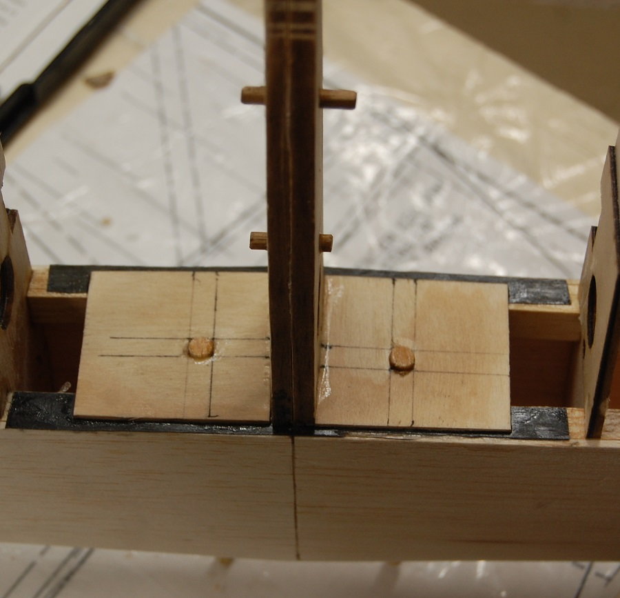
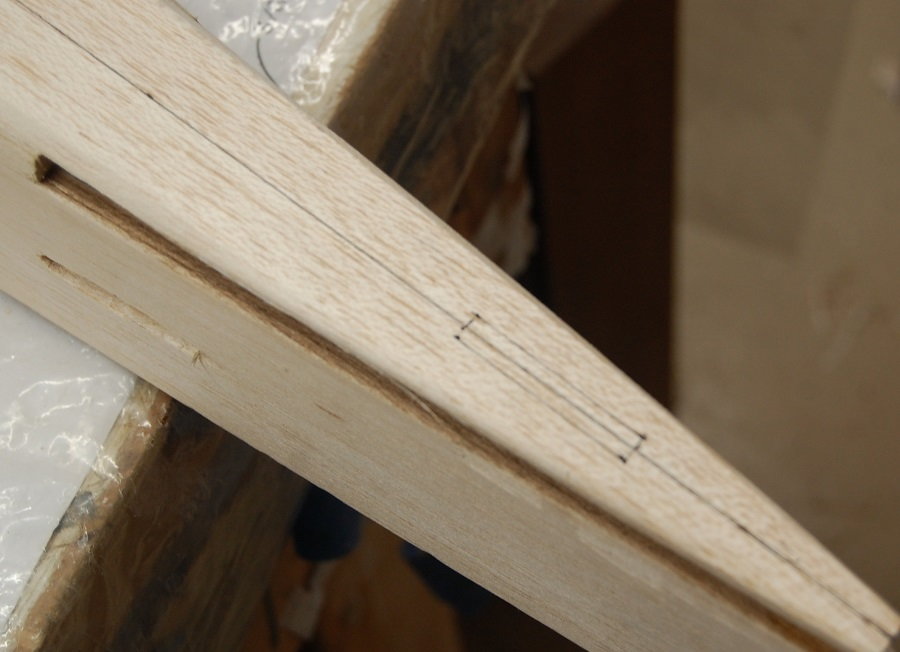
I'm leading off this post with a photo of the top deck back at the tail. You can see where I have marked out the slot for mounting the fin. It isn't shown on teh original plans but the laser cut parts include a tab on the bottom of the fin. This will provide a stronger glue joint but it is important to center the slot so that the fin sits on the centerline of the airframe and to cut the slot accurately so that there is a snug fit and thus a strong glue joint.
Servo mounts. Just some 3/8 basswood rails for mounting the servos. In hindsight one thing I would have done differently is to mount the servos a little farther forward in the fuselage. With the aileron servos mounted in the wing clearance for the aileron linkage isn't an issue and by moving the servos a bit farther forward it would leave more room for the wing hold down bolts. It's not a critical issue, more just a matter of my own taste. Relating to servos and personal taste, I had a chance to examine a Super Kaos that had individual elevator servos mounted in the tail on either side of the fuselage in the manner of a lot of 3-D airplanes. This was in a competition airplane at an SPA contest. The owner indicated that this setup didn't confer any particular advantage and that if he were to do it again he would just use the stock setup with a pushrod and a wire joiner for the elevator halves.
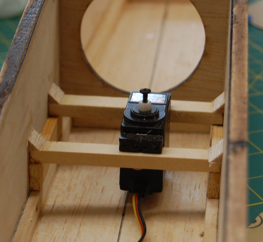
A view of the front anchor points for the pushrods. Pretty standard stuff. The pushrod sheaths will be tied to the frame before i add the bottom sheeting. The rods cross so that I can get the straightest possible shot from the servo to the control surface.
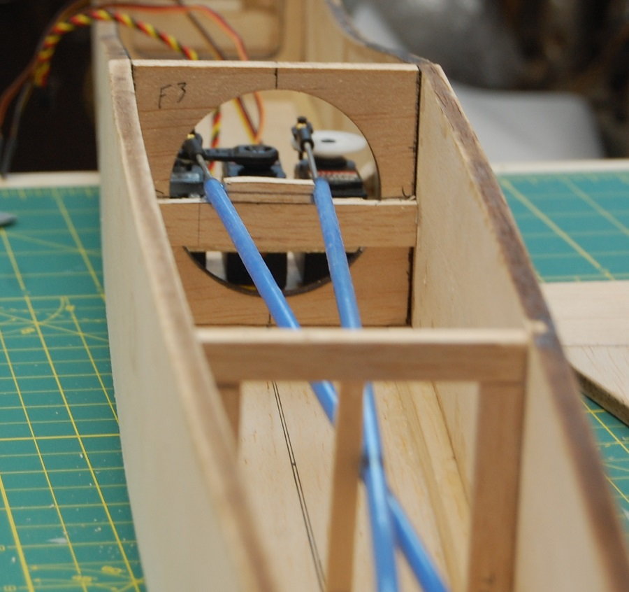
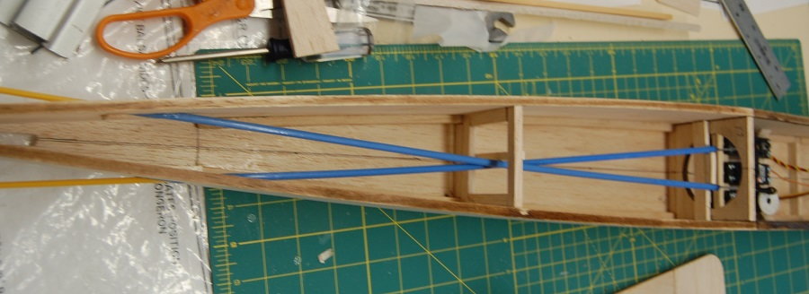
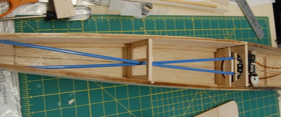
Here are the pushrod runs from to the nose gear and the throttle. There is plenty of room in the fuselage for the receiver and battery. The passage through F2 is just the right size for the 12 oz. fuel tank called for in the plans. There is plenty of room under the tank for the flight battery but given that the Eagle .60 is pretty hefty I am probably going to mount the battery just behind F2. For those contemplating electric power, a battery tray between the firewall and F2 and a hatch on top of the tank compartment should make for easy access.
Servo mounts. Just some 3/8 basswood rails for mounting the servos. In hindsight one thing I would have done differently is to mount the servos a little farther forward in the fuselage. With the aileron servos mounted in the wing clearance for the aileron linkage isn't an issue and by moving the servos a bit farther forward it would leave more room for the wing hold down bolts. It's not a critical issue, more just a matter of my own taste. Relating to servos and personal taste, I had a chance to examine a Super Kaos that had individual elevator servos mounted in the tail on either side of the fuselage in the manner of a lot of 3-D airplanes. This was in a competition airplane at an SPA contest. The owner indicated that this setup didn't confer any particular advantage and that if he were to do it again he would just use the stock setup with a pushrod and a wire joiner for the elevator halves.
A view of the front anchor points for the pushrods. Pretty standard stuff. The pushrod sheaths will be tied to the frame before i add the bottom sheeting. The rods cross so that I can get the straightest possible shot from the servo to the control surface.
Here are the pushrod runs from to the nose gear and the throttle. There is plenty of room in the fuselage for the receiver and battery. The passage through F2 is just the right size for the 12 oz. fuel tank called for in the plans. There is plenty of room under the tank for the flight battery but given that the Eagle .60 is pretty hefty I am probably going to mount the battery just behind F2. For those contemplating electric power, a battery tray between the firewall and F2 and a hatch on top of the tank compartment should make for easy access.
05-27-2019, 04:48 PM
#43
Nice build, I'm looking at buying a Kaos short kit myself, even though there's nothing wrong with my scratch built kwik fli III. I love old pattern planes even if they aren't quite as capable as the newer guppy designs.
You are going to add bracing to capture those control rod sleeves, yes? Otherwise you could get some unwanted bendy-bendy. I like to use 1/8" ply, drill holes slightly larger than sleeve dia, cut in half and glue one half to the former and glue the other half on to completely capture the sleeve. I don't use golden rods anywhere in a pattern plane as they can expand/contract with temp changes and mess with trim settings. I do use golden cable for throttle setups when airframe design damands.
You are going to add bracing to capture those control rod sleeves, yes? Otherwise you could get some unwanted bendy-bendy. I like to use 1/8" ply, drill holes slightly larger than sleeve dia, cut in half and glue one half to the former and glue the other half on to completely capture the sleeve. I don't use golden rods anywhere in a pattern plane as they can expand/contract with temp changes and mess with trim settings. I do use golden cable for throttle setups when airframe design damands.
Last edited by Glowgeek; 05-27-2019 at 05:02 PM.
 05-27-2019, 08:21 PM
#44
Thread Starter
Nice build, I'm looking at buying a Kaos short kit myself, even though there's nothing wrong with my scratch built kwik fli III. I love old pattern planes even if they aren't quite as capable as the newer guppy designs.
You are going to add bracing to capture those control rod sleeves, yes? Otherwise you could get some unwanted bendy-bendy. I like to use 1/8" ply, drill holes slightly larger than sleeve dia, cut in half and glue one half to the former and glue the other half on to completely capture the sleeve. I don't use golden rods anywhere in a pattern plane as they can expand/contract with temp changes and mess with trim settings. I do use golden cable for throttle setups when airframe design damands.
You are going to add bracing to capture those control rod sleeves, yes? Otherwise you could get some unwanted bendy-bendy. I like to use 1/8" ply, drill holes slightly larger than sleeve dia, cut in half and glue one half to the former and glue the other half on to completely capture the sleeve. I don't use golden rods anywhere in a pattern plane as they can expand/contract with temp changes and mess with trim settings. I do use golden cable for throttle setups when airframe design damands.

 05-28-2019, 07:45 AM
#46
Thread Starter
Too true. I usually use a product called Kwik-Poly. It's one of those "good for lots of stuff" products. It is a two part resin that has a very thin consistency. It seems to be fuel proof to both glow fuel and gasoline. It flows into lightweight fiberglass very nicely and I've used it to glass several airplanes. I usually buy it direct from the company but I've seen it advertised by veterinary supply houses as an adhesive for repairing horses' hooves. It has a very short pot life but you can usually sand on it within half an hour.
05-29-2019, 07:25 AM
#47
Thread Starter
Well... after all that talk about how nice Kwik Poly is I just found out that they closed up shop back in January. The facebook page indicated they closed due to the proprietors health.  Given that this stuff was also used in the antique car restoration business and other professions I wonder if someone will pick up the business.
Given that this stuff was also used in the antique car restoration business and other professions I wonder if someone will pick up the business.