


Super Kaos from Lazerworks Short Kit.
 06-02-2019, 07:41 AM
#76

Thread Starter

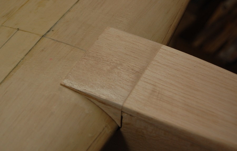
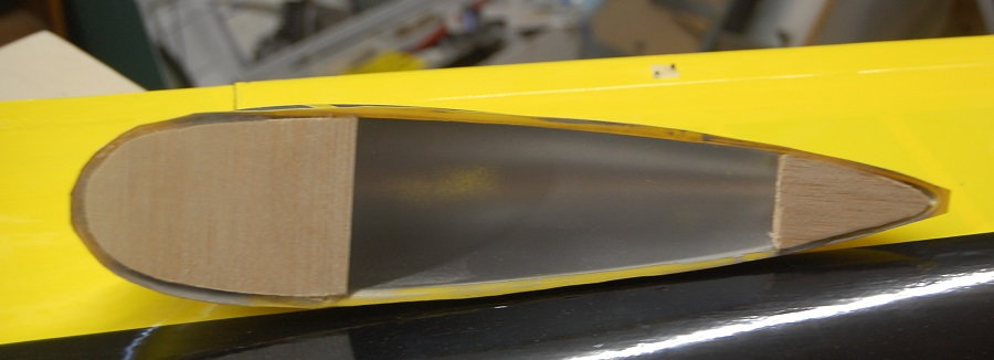
Time to start building up the fairing that covers the joint between the leading edge of the wing and the fuselage. For this first bit I just used some left over material from the sheets that the fuselage sides were cut from. The fairing doesn't contribute much to the structure but it adds a lot to the appearance of the airplane. It's just a build it up and carve/sand it to shape attachment.
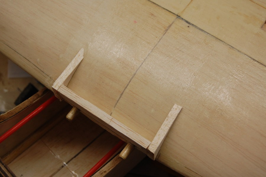
The first cross piece was a piece of 1/16 sheet.
An angle view of how the fairing sits.
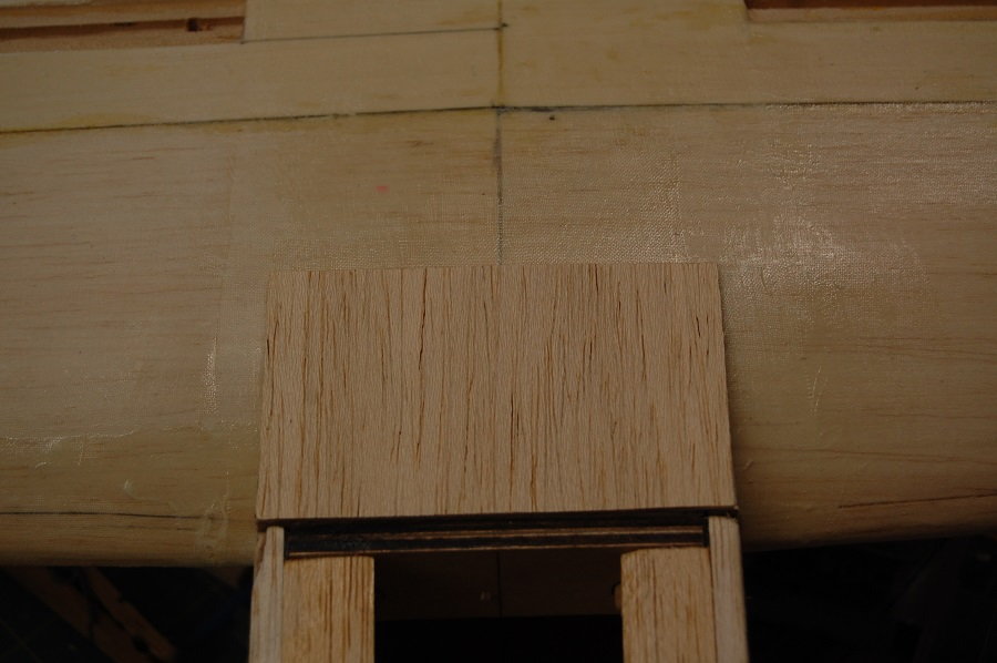
Oops, grabbed a large photo instead of one that had been resized. It shows the addition of the floor of the nose section of the fuselage. The plans call the floor of the nose a "balsa block" but it is really 3/8 or 1/2 inch thick sheet. In my case I used 3/8 sheet cut to length and then after the sheet was glued to the bottom of the fuselage it was trimmed to match the sides. 1/2 inch sheet on the nose would provide material for a more rounded shape if desired.
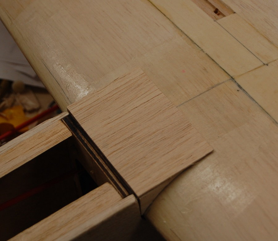
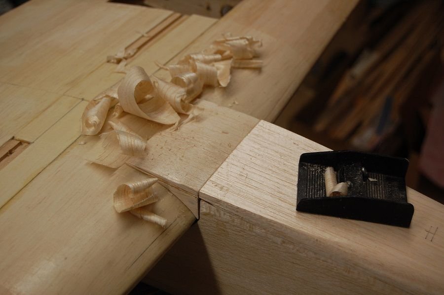
Some 3/16 sheet was added to the fairing to match the thickness of the thickness of the 3/8 sheet on the nose. The material on the back of the fairing was shaved down to meet the surface of the wing and you can see that shaping and sanding has been done to begin to match up the wing fairing to the bottom of the nose.
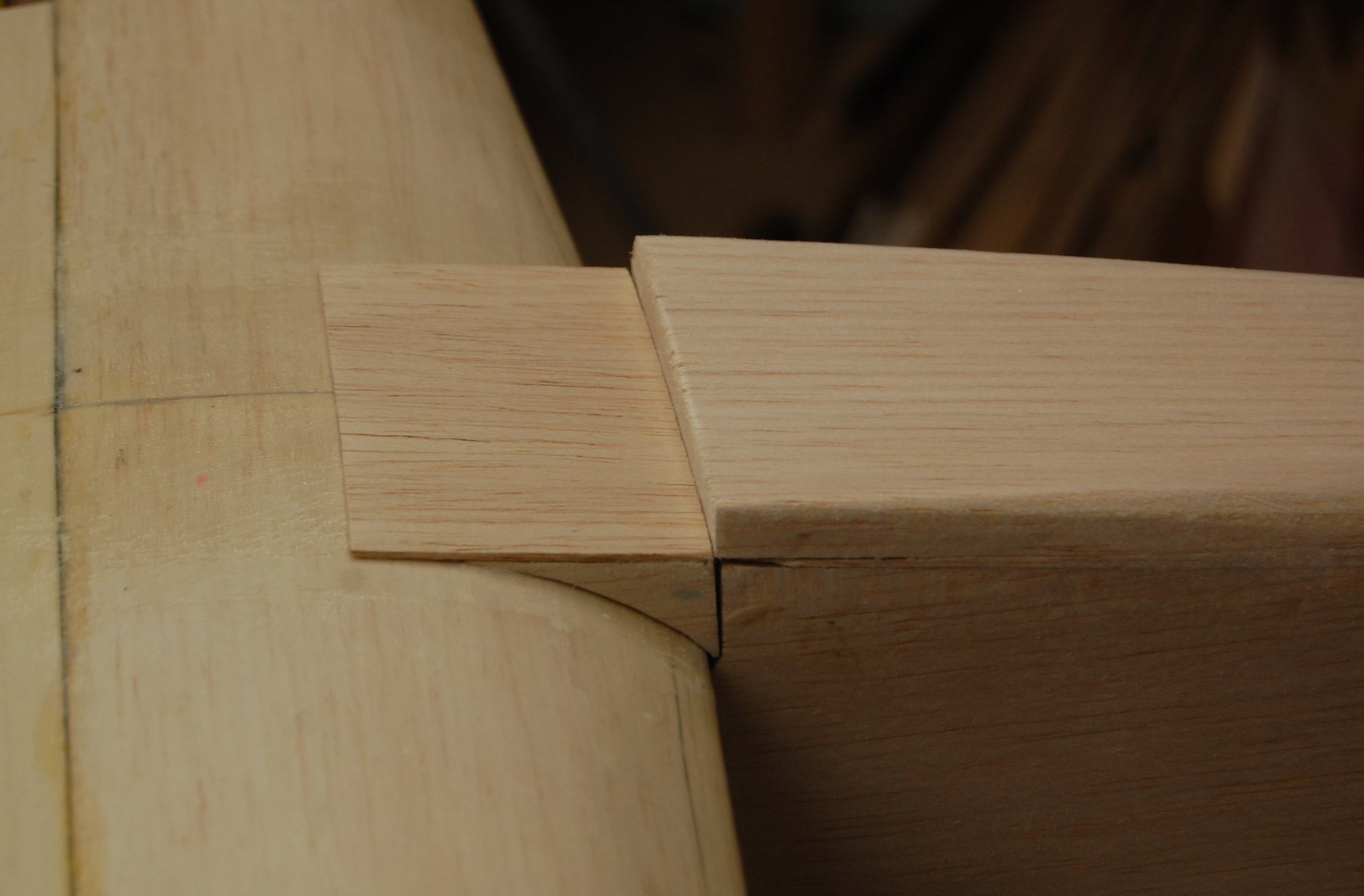
Here is a picture of the shaping in progress. If you keep the blade sharp, even a cheap plastic plane can do a good job. I've also got a couple of small hand planes but I only just got them out of storage and the need cleaning and sharpening.
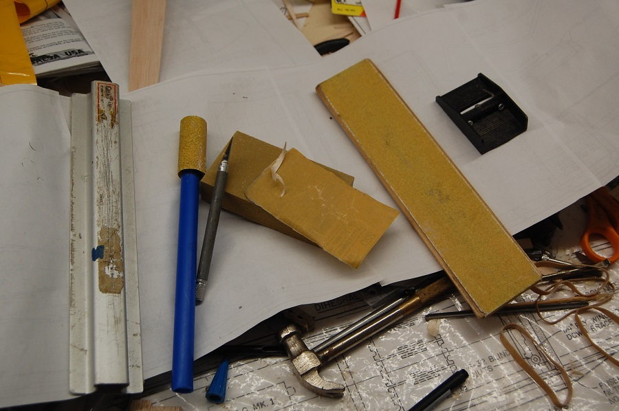
The shaping tools used on this model. Sharp blades and fresh sandpaper are your friends. Found objects such as the bit of blue plastic tubing can be handy when you want a sanding bar of a particular shape.
The first cross piece was a piece of 1/16 sheet.
An angle view of how the fairing sits.
Oops, grabbed a large photo instead of one that had been resized. It shows the addition of the floor of the nose section of the fuselage. The plans call the floor of the nose a "balsa block" but it is really 3/8 or 1/2 inch thick sheet. In my case I used 3/8 sheet cut to length and then after the sheet was glued to the bottom of the fuselage it was trimmed to match the sides. 1/2 inch sheet on the nose would provide material for a more rounded shape if desired.
Some 3/16 sheet was added to the fairing to match the thickness of the thickness of the 3/8 sheet on the nose. The material on the back of the fairing was shaved down to meet the surface of the wing and you can see that shaping and sanding has been done to begin to match up the wing fairing to the bottom of the nose.
Here is a picture of the shaping in progress. If you keep the blade sharp, even a cheap plastic plane can do a good job. I've also got a couple of small hand planes but I only just got them out of storage and the need cleaning and sharpening.
The shaping tools used on this model. Sharp blades and fresh sandpaper are your friends. Found objects such as the bit of blue plastic tubing can be handy when you want a sanding bar of a particular shape.
 06-02-2019, 08:03 AM
#77
Thread Starter
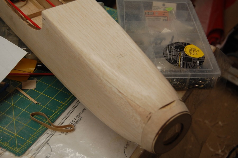
The bottom of the nose after quite a bit of shaping and sanding has been done. At the very front you can see the plywood ring that comes with the laser cut parts. With the engine installed the ring should be centered on the prop driver and the prob driver should extend beyond the ring just afar enough for the spinner to clear the front of the fuselage. In this case about 5/8ths of an inch of stacked sheet was glued to the nose to space the plywood ring in the desired position. The amount of material used here will depend n the length of your engine. For example, a .90 four-stroke would require a longer nose to cover the front of the engine. If using a brushless electric motor I expect that the placement of the motor for balance purposes would determine how long the nose would need to be. In looking at the very front of the nose you can see that a lot of material has been removed to get the round shape. In the lower corners the shape has been sanded down into the triangle stock. That is what it is there for. The idea is to shape the nose down to the diameter of the plywood ring. You will notice that there are a couple of spots where I didn't cut the additional material on the nose quite big enough You could use filler here but I will just glue in a little additional wood and finish sanding.
06-03-2019, 06:20 AM
#78
My Feedback: (2)
Hi Matt, you are truely a great builder my friend and I don't have the skill you do!. I am trying to get this TH Kaos ARF done and the more I go the more problems I find with it but its almost ready. I got a brand new OS 46 broke in last week ready to go right in!
Take Care
Michael Johnston
Take Care
Michael Johnston
06-03-2019, 08:49 AM
#80
Thread Starter
Thanks for the compliments but I have to admit; it is often more a matter of persistence rather than skill. Except for those time when it is a "teachable moment" I tend to edit around my screw-ups.
06-04-2019, 07:57 AM
#82
Thread Starter
I generally don't like to add any more hatches than are necessary. In this case I have decided to add one, mostly for access to the nose gear. Although it isn't on the original plan it seems fairly common to add a fuselage hatch. I've even seen one where the hatch ran all the way back to the aft end of the canopy. I'm just using the basic screw and tab mounting. If one were going with electric power you could probably extend the hatch all the way back to F2 and mount it with rare earth magnets.
Just a styrofoam block to help with positioning the fuel tank. If you need the nose weight this would be a good spot for the battery pack.

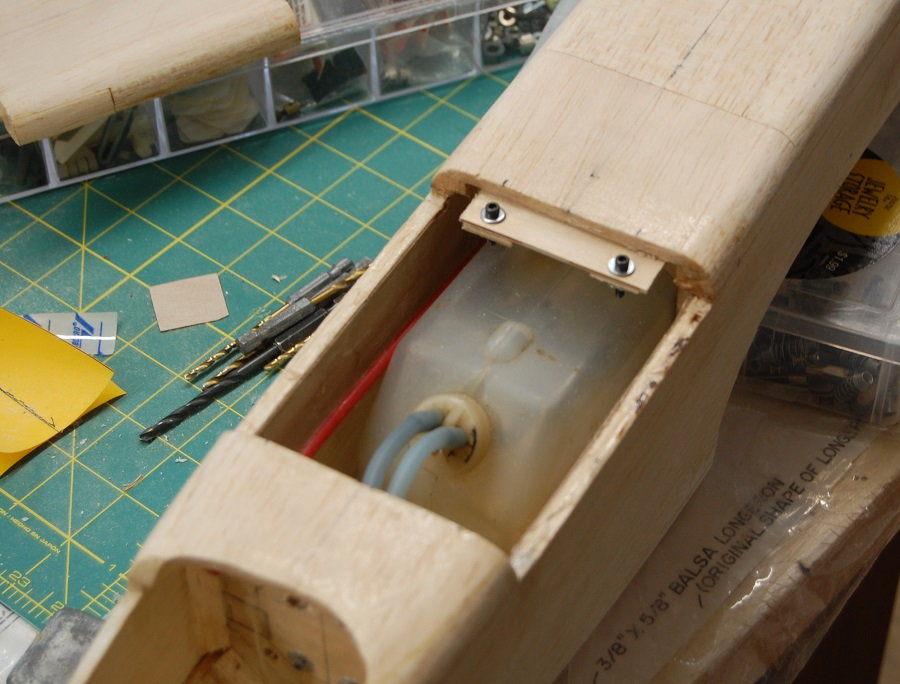
A couple of 4-40 screws anchored in blind nuts will hold down the hatch. To separate the hatch I cut through the top deck very carefully with a razor saw. It was then parted from the sides using a fresh x-acto knife. The fuel tank shown is a 12 oz Sullivan tank. I'll be using a fresh one as this tank has seen a few flights and is kind of dirty.
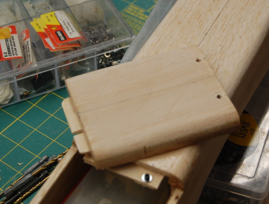
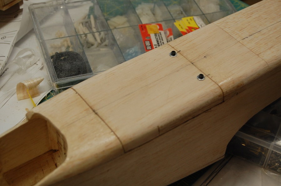
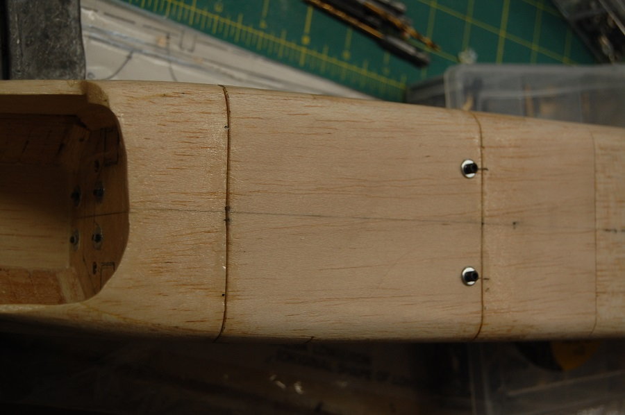
A couple of shots of the hatch buttoned up.
Just a styrofoam block to help with positioning the fuel tank. If you need the nose weight this would be a good spot for the battery pack.
A couple of 4-40 screws anchored in blind nuts will hold down the hatch. To separate the hatch I cut through the top deck very carefully with a razor saw. It was then parted from the sides using a fresh x-acto knife. The fuel tank shown is a 12 oz Sullivan tank. I'll be using a fresh one as this tank has seen a few flights and is kind of dirty.
A couple of shots of the hatch buttoned up.
06-05-2019, 09:08 AM
#83
Thread Starter
A few views of the horizontal tail. It is covered in Ultracote. If you look back in the build the main part of the tail is built up and sheeted to 3/8 inch thickness. The elevators are cut from medium hard 3/8 sheet and given a relatively coarse taper.
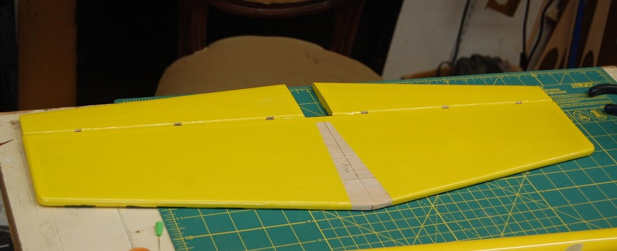
I mounted the elevators with hinge points. I like them because they are strong, low friction and easy to align. As with a lot of plastic parts a quick wipe with lacquer thinner or other solvent removes mold release and promotes adhesion while a tiny dab of Vaseline or other lubricant in the hinge itself keeps any loose glue from clogging things up. The leading edged of the elevators are beveled for clearance and the hinges are inset into the leading edge of the elevator by about 1/16 inch. This gives a nice tight hinge line with an elevator throw that well exceeds the amount called for in the original build article (3/8 inch up and down).
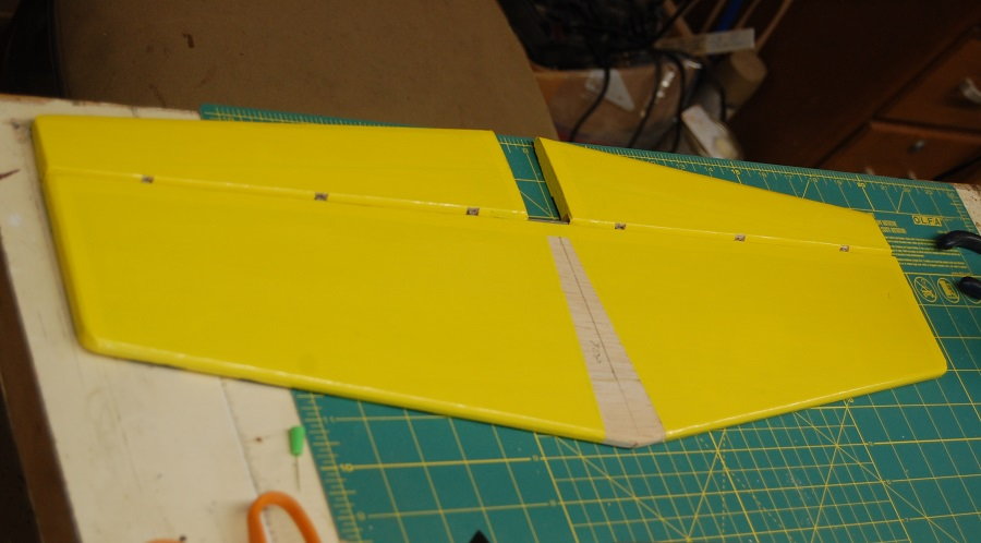
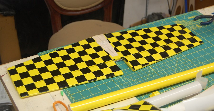
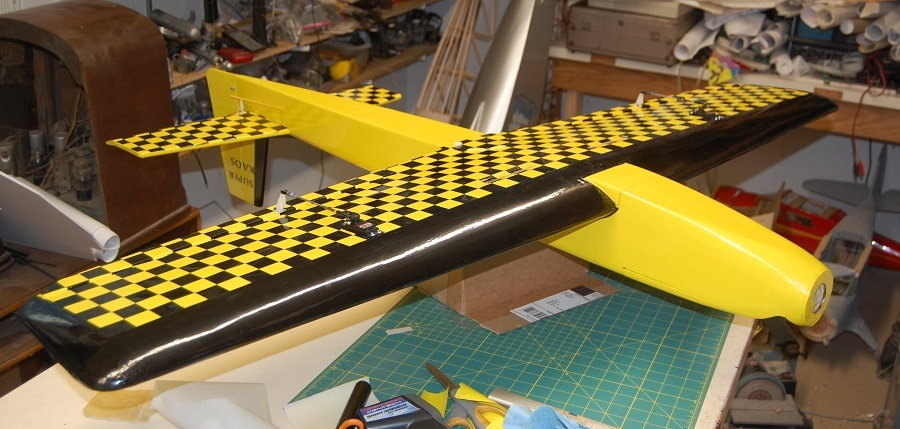
Time to dress things up a little with some checker board. It's a good thing Ultracote comes in checkerboard pattern. I know people who can and have done this by hand but I don't know that I could go there. I've seen discussions of how to cut away the covering for mounting tail surfaces. Luckily for me this isn't an arf and I can lay out the covering myself. Just insert the tail into the fuselage and mark the lines where the tail meets the fuselage and cover right to that line.
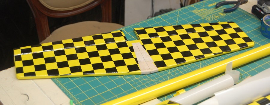
You can see where the checkerboard aligns with the trailing edge of the horizontal tail. That was a convenient reference line for me. It doesn't have to be that particular point but having some sort of reference line helps to keep the checks aligned. I should point out that the elevators were covered before the hinges were glued in. It is easier to align the checks with no hinges in the way. In covering the elevators I cut the Ultracote with a couple of rows of checks for sacrificial material. After my early years of having to stretch a roll of covering as far as it would go it feels wasteful to cut the covering that wide but it is necessary for getting the alignment right. You can use a bit of masking tape to hold the covering in place while you sort out the alignment and then tack it down in a couple of places. Once you have it in place you can trim the covering to meet the edges of the elevator and finish ironing it down. It doesn't show well in the photos but I had to allow a bit of extra material for the bevels on the front of the elevator. You will want the checkers to visually align when you are looking straight down onto the assembly. Practicing on a bit of scrap that includes the elevator bevels helps. The elevators are connected with the tried and true music wire joiner. Take your time and tweak that wire until the elevators will lay perfectly flat with the leading edges of the elevators laying parallel to one another. This helps eliminate binding and it makes the airplane easier to trim when you aren't wondering where that persistent bit of roll is coming from.
I mounted the elevators with hinge points. I like them because they are strong, low friction and easy to align. As with a lot of plastic parts a quick wipe with lacquer thinner or other solvent removes mold release and promotes adhesion while a tiny dab of Vaseline or other lubricant in the hinge itself keeps any loose glue from clogging things up. The leading edged of the elevators are beveled for clearance and the hinges are inset into the leading edge of the elevator by about 1/16 inch. This gives a nice tight hinge line with an elevator throw that well exceeds the amount called for in the original build article (3/8 inch up and down).
Time to dress things up a little with some checker board. It's a good thing Ultracote comes in checkerboard pattern. I know people who can and have done this by hand but I don't know that I could go there. I've seen discussions of how to cut away the covering for mounting tail surfaces. Luckily for me this isn't an arf and I can lay out the covering myself. Just insert the tail into the fuselage and mark the lines where the tail meets the fuselage and cover right to that line.
You can see where the checkerboard aligns with the trailing edge of the horizontal tail. That was a convenient reference line for me. It doesn't have to be that particular point but having some sort of reference line helps to keep the checks aligned. I should point out that the elevators were covered before the hinges were glued in. It is easier to align the checks with no hinges in the way. In covering the elevators I cut the Ultracote with a couple of rows of checks for sacrificial material. After my early years of having to stretch a roll of covering as far as it would go it feels wasteful to cut the covering that wide but it is necessary for getting the alignment right. You can use a bit of masking tape to hold the covering in place while you sort out the alignment and then tack it down in a couple of places. Once you have it in place you can trim the covering to meet the edges of the elevator and finish ironing it down. It doesn't show well in the photos but I had to allow a bit of extra material for the bevels on the front of the elevator. You will want the checkers to visually align when you are looking straight down onto the assembly. Practicing on a bit of scrap that includes the elevator bevels helps. The elevators are connected with the tried and true music wire joiner. Take your time and tweak that wire until the elevators will lay perfectly flat with the leading edges of the elevators laying parallel to one another. This helps eliminate binding and it makes the airplane easier to trim when you aren't wondering where that persistent bit of roll is coming from.
06-06-2019, 08:05 AM
#85
Thread Starter
Beginning to cover the wings. Just under the leading edge you can see the handle of my cheap IR thermometer. It probably isn't the most accurate but it is good enough for calibrating my covering iron. It's old hat for lots of builders but it really does make a big difference when you can alternate between "activate the adhesive" and "make it shrink" temperatures. I took the opportunity to go ahead and install the servos after the bottom of the wing was covered but while things were still accessible from the top. You can also see where the ends of the ailerons got a bit of covering before assembly. The two black strips on the trailing edge are a couple of bits of gratuitous carbon fiber. Before I glued on the plywood plate on the bottom of the wing the trailing edge had seemed a little flimsy. As it now is I think it is plenty strong but if I were doing it again I would have moved the wing bolts forward about 1.5 inches. This is a change that was done with the Ultimate Kaos which was designed with the aileron servos out in the wing panels.
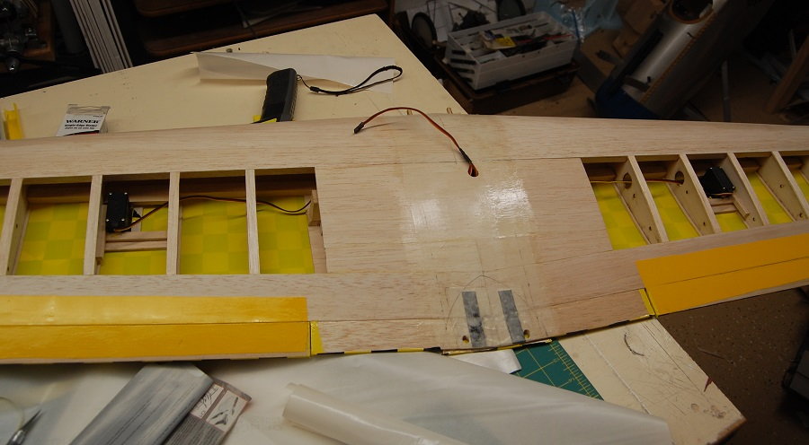
The main part of the bottom of the wing was covered with a single piece of Ultracote. The checkerboard line up on the wing spar. The ailerons are covered separately in the same manner as the elevators. The Ultracote was cut on an angle to match the taper of the wing, tacked down and trimmed to match the bevel of the aileron leading edge before sealing down.
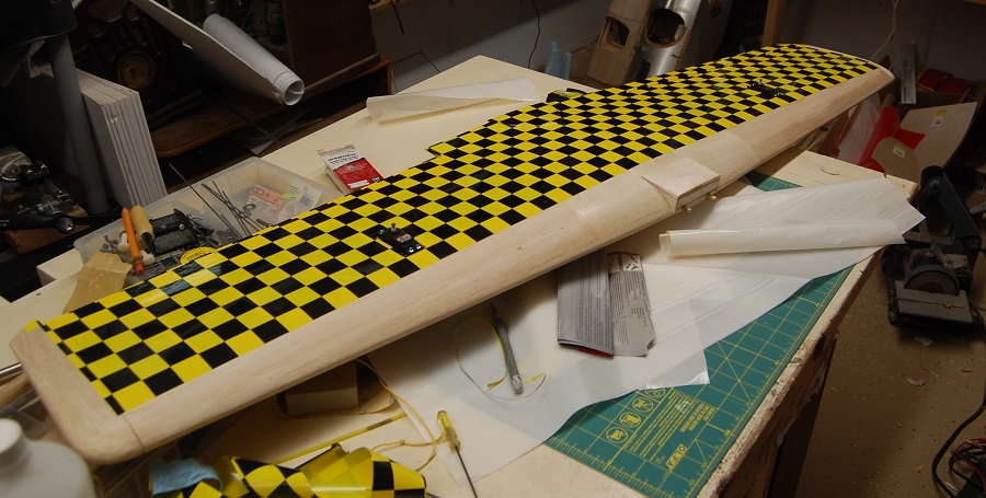
The top of the wing is covered in a similar manner. The wing and aileron are covered with a single piece of covering. The inboard and outboard ends of the aileron are cut free and the covering is sealed into the seam of the solartex hinge. This provides an attractive, airtight aileron hinge. If you go for this type of hinge be mindful of the color of the fabric you are using. Strongly contrasting colors will likely show through the Ultracote. The downward throw on the aileron is limited by the bevel on the leading edge of the aileron. As build It can easily exceed the recommended 1/4 inch throws.

The main part of the bottom of the wing was covered with a single piece of Ultracote. The checkerboard line up on the wing spar. The ailerons are covered separately in the same manner as the elevators. The Ultracote was cut on an angle to match the taper of the wing, tacked down and trimmed to match the bevel of the aileron leading edge before sealing down.
The top of the wing is covered in a similar manner. The wing and aileron are covered with a single piece of covering. The inboard and outboard ends of the aileron are cut free and the covering is sealed into the seam of the solartex hinge. This provides an attractive, airtight aileron hinge. If you go for this type of hinge be mindful of the color of the fabric you are using. Strongly contrasting colors will likely show through the Ultracote. The downward throw on the aileron is limited by the bevel on the leading edge of the aileron. As build It can easily exceed the recommended 1/4 inch throws.
06-07-2019, 04:42 AM
#88
Coming along nicely Matt and I'm enjoying seeing your attention to detail.
Hard to tell in the pics just how smooth/glossy the Solartex film is, just wondering how well the Monokote sticks to it.
Also, looking back at your Solartex hinging post you said the Solartex strips were sewn together. Did you use 100% polyester thread or something else?
Hard to tell in the pics just how smooth/glossy the Solartex film is, just wondering how well the Monokote sticks to it.
Also, looking back at your Solartex hinging post you said the Solartex strips were sewn together. Did you use 100% polyester thread or something else?
Last edited by Glowgeek; 06-07-2019 at 04:50 AM.
06-07-2019, 08:02 AM
#89
Thread Starter
Coming along nicely Matt and I'm enjoying seeing your attention to detail.
Hard to tell in the pics just how smooth/glossy the Solartex film is, just wondering how well the Monokote sticks to it.
Also, looking back at your Solartex hinging post you said the Solartex strips were sewn together. Did you use 100% polyester thread or something else?
Hard to tell in the pics just how smooth/glossy the Solartex film is, just wondering how well the Monokote sticks to it.
Also, looking back at your Solartex hinging post you said the Solartex strips were sewn together. Did you use 100% polyester thread or something else?
 Regarding Solartex hinges: I've never had any difficulty getting Solartex to to stick to itself or anything else. Film over Solartex doesn't seem to trap air bubbles nearly so often as film over film. I would say that it is due to the fabric texture of the Solartex. I don't know how Solartex was manufactured but the weave of the dacron cloth is clearly visible from the upper side. I would describe it as having a semigloss sheen. I did give the Solartex a quick wipe with alcohol just to remove any skin oil from being handled. It's been a long time since I tried this with actual Monocote brand film so I would try a sample before I committed to putting it on a plane. I'm pretty certain that the thread used for the hinge was was polyester sewing thread. I just cut two strips of Solartex and ran them through an old sewing machine. It is a much lighter thread than what would be used for the old figure eight style sewn hinges. The strength of the hinge comes from being hinged across its entire length and the Ultracote adheres to the thread and prevents it from ever unraveling. While Solartex is no longer manufactured, Balsa USA is now importing Oracover. I haven't had a chance to try it out but based on appearance it should function in the same manner. I occasionally do thing like these hinges that work well for me but as whenever trying out a new technique I strongly suggest that you try it out on a bit of scrap material. Your mileage may vary.
06-07-2019, 08:50 AM
Regarding Solartex hinges: I've never had any difficulty getting Solartex to to stick to itself or anything else. Film over Solartex doesn't seem to trap air bubbles nearly so often as film over film. I would say that it is due to the fabric texture of the Solartex. I don't know how Solartex was manufactured but the weave of the dacron cloth is clearly visible from the upper side. I would describe it as having a semigloss sheen. I did give the Solartex a quick wipe with alcohol just to remove any skin oil from being handled. It's been a long time since I tried this with actual Monocote brand film so I would try a sample before I committed to putting it on a plane. I'm pretty certain that the thread used for the hinge was was polyester sewing thread. I just cut two strips of Solartex and ran them through an old sewing machine. It is a much lighter thread than what would be used for the old figure eight style sewn hinges. The strength of the hinge comes from being hinged across its entire length and the Ultracote adheres to the thread and prevents it from ever unraveling. While Solartex is no longer manufactured, Balsa USA is now importing Oracover. I haven't had a chance to try it out but based on appearance it should function in the same manner. I occasionally do thing like these hinges that work well for me but as whenever trying out a new technique I strongly suggest that you try it out on a bit of scrap material. Your mileage may vary.
06-07-2019, 08:50 AM
#90
Thread Starter
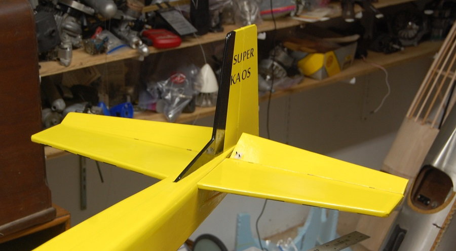
A quick look at the fin and rudder just after covering. The tab on the bottom of the fin inserts into a slot cut on the top of the fuselage. Yellow Ultracote is slightly translucent and you can see the change in the grain of the wood at the bottom of the rudder.
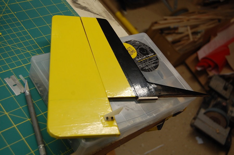
Lazerworks also supplied a nice set of iron on markings. Given that the fin and rudder are just cut from sheet I went ahead and used CA hinges. There is no reason why you couldn't use your preferred type of hinges. Unless there is a call for a specific type of hinge my choices are often influenced by ease of use and what's in the parts bin.
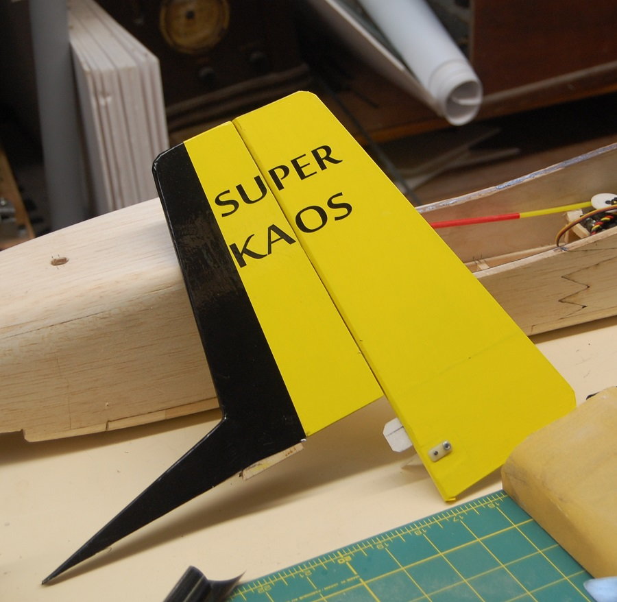
Here is the tail installed on the airplane. As you might guess I got on a roll with covering and forgot to take photos of the fuselage during the covering process. Given that the fuselage is basically a box with the corners sanded off, it doesn't present too many challenges. I will point out that you should leave a strip uncovered for the fin to attach to the fuselage. Early in the build I marked the centerline of the fuselage. This line is faintly visible through the Ultracote. The centerline was used to center the slot for the tab on the fin and for the removal of covering to provide a surface for the fin to glue to. Getting the fin centered on the thrust line and square to the horizontal tail is one of the more fiddly things to do on this airplane but it will pay off with an airplane that flies true and is easier to trim. This is also where you find out how squarely you built your fuselage. The angles of the horizontal tail are set by the tops of the fuselage sides. If your fuselage is true then the horizontal tail will be square to the wing. Actually since the horizontal is the first thing that you actually build, you should be checking this all along. Little nuggets of wisdom like this are why you should read the entire manual or read through an entire thread before you start building your own. Several of the Kaos series of airplanes had build articles in RCM magazine and copes of these can be found online. It doesn't show well in the bottom photo but there is an insert that runs from the back of the horizontal tail to the rudder and fits between the elevators. It is just a chunk of 3/8 stock that fill in the rest of the slot where the horizontal tail attached to the fuselages. It is structural as it stiffens the last two inches of the tail where the fin glues to the fuselage. Just be sure to leave a bit of room so that it doesn't foul on the wire joiner for the elevators.
Lazerworks also supplied a nice set of iron on markings. Given that the fin and rudder are just cut from sheet I went ahead and used CA hinges. There is no reason why you couldn't use your preferred type of hinges. Unless there is a call for a specific type of hinge my choices are often influenced by ease of use and what's in the parts bin.
Here is the tail installed on the airplane. As you might guess I got on a roll with covering and forgot to take photos of the fuselage during the covering process. Given that the fuselage is basically a box with the corners sanded off, it doesn't present too many challenges. I will point out that you should leave a strip uncovered for the fin to attach to the fuselage. Early in the build I marked the centerline of the fuselage. This line is faintly visible through the Ultracote. The centerline was used to center the slot for the tab on the fin and for the removal of covering to provide a surface for the fin to glue to. Getting the fin centered on the thrust line and square to the horizontal tail is one of the more fiddly things to do on this airplane but it will pay off with an airplane that flies true and is easier to trim. This is also where you find out how squarely you built your fuselage. The angles of the horizontal tail are set by the tops of the fuselage sides. If your fuselage is true then the horizontal tail will be square to the wing. Actually since the horizontal is the first thing that you actually build, you should be checking this all along. Little nuggets of wisdom like this are why you should read the entire manual or read through an entire thread before you start building your own. Several of the Kaos series of airplanes had build articles in RCM magazine and copes of these can be found online. It doesn't show well in the bottom photo but there is an insert that runs from the back of the horizontal tail to the rudder and fits between the elevators. It is just a chunk of 3/8 stock that fill in the rest of the slot where the horizontal tail attached to the fuselages. It is structural as it stiffens the last two inches of the tail where the fin glues to the fuselage. Just be sure to leave a bit of room so that it doesn't foul on the wire joiner for the elevators.
06-08-2019, 12:34 PM
#91
Thread Starter
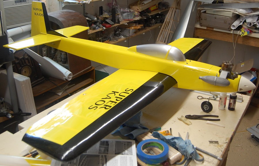
The basic covering is done. It still lacks a canopy and landing gear. The controls aren't hooked up yet. It isn't the most elaborate covering job you will ever see or the best but it satisfies the criteria of high visibility and ease of distinguishing orientation. The rounded wing tips took a bit of effort. I just used the technique of tacking to covering along the rib line of the wing time and then tugging and tacking the covering toward the midline of the tip. There are tutorials on how to do this but I can tell that I need more practice. Aesthetically, I'm still debating on whether or not I should have rounded the corner where the black of the wing tip joins the black of the leading edge. The Super Kaos plans do show a small wing root fairing. I have the material and had gone so far as to lay out the cuts. The bottom line is I just didn't feel like messing with them and the airplane will fly just fine without them. I covered the fuselage before installing the tail surfaces. It's just easier than trying to work the covering down onto the joint where the surfaces meet.
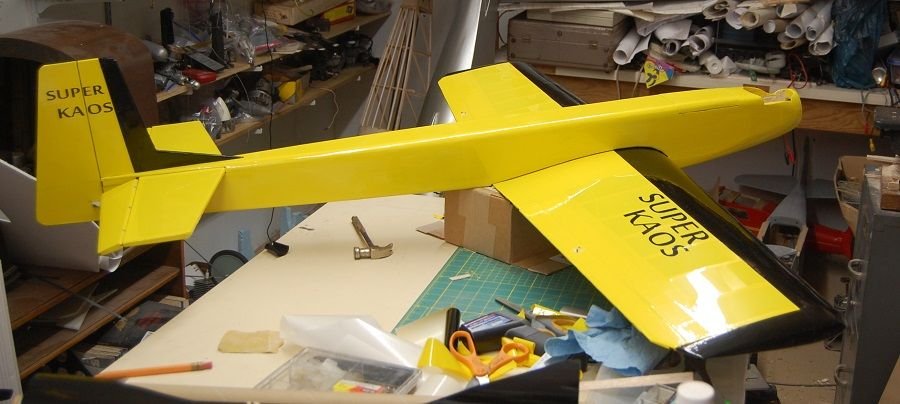
This shows the belly of the airplane. The fairing on the leading edge of the wing was covered in yellow first and the the black of the leading edge was cut to fit around it. There was a question earlier in the thread about how I dealt with the curves on the fuselage. I envy the skill of those people who seem to be able to cover a fuselage with a single piece of covering like it was a piece of heat shrink tubing going around a wire. In my case I covered bottom, then sides and finally the top of the fuselage. If you are careful with your heat you can stretch as well as shrink film covering. In my case I worked the covering around the curves of the nose by tacking the covering down along the centerline and then rubbing the covering with a bit of soft cloth to be sure that it was adhered to the airplane. I let the covering cool so that it is well anchored and then I start heating and pulling the covering so that it conforms to the curves of the nose. You can also see that I have installed the aileron servos and their linkage. The linkage is simple and direct. A ball joint at the servo end minimizes slop and a clevis at the aileron horn provided for fine mechanical adjustment. I'm running my ailerons on a Y-harness but as discussed earlier setting up the ailerons on separate channels is an option along with the advantages that setup would bring.
This shows the belly of the airplane. The fairing on the leading edge of the wing was covered in yellow first and the the black of the leading edge was cut to fit around it. There was a question earlier in the thread about how I dealt with the curves on the fuselage. I envy the skill of those people who seem to be able to cover a fuselage with a single piece of covering like it was a piece of heat shrink tubing going around a wire. In my case I covered bottom, then sides and finally the top of the fuselage. If you are careful with your heat you can stretch as well as shrink film covering. In my case I worked the covering around the curves of the nose by tacking the covering down along the centerline and then rubbing the covering with a bit of soft cloth to be sure that it was adhered to the airplane. I let the covering cool so that it is well anchored and then I start heating and pulling the covering so that it conforms to the curves of the nose. You can also see that I have installed the aileron servos and their linkage. The linkage is simple and direct. A ball joint at the servo end minimizes slop and a clevis at the aileron horn provided for fine mechanical adjustment. I'm running my ailerons on a Y-harness but as discussed earlier setting up the ailerons on separate channels is an option along with the advantages that setup would bring.
06-09-2019, 12:51 AM
#93
Matt, don't sell yourself short, you did a fantastic job! The color scheme is simple but effective as you had said. Once you complete this bird and bring it to your flying field, I'm sure it will garner the attention of many. Keep going, you're almost there...
06-09-2019, 05:09 AM
#94
Thread Starter
06-09-2019, 08:49 PM
#96
Thread Starter
06-11-2019, 06:51 PM
#98
Thread Starter
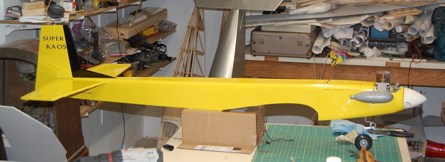
Here is the Super Kaos with the nose gear under it and the engine in place. I need to clean some of the baked on castor off of the engine. The engine is fresh but previously lived inside a cowl where it wasn't convenient to wipe the oil off between flights. The spinner is just sitting on the prop shaft. I will probably swap it out for a matching color.
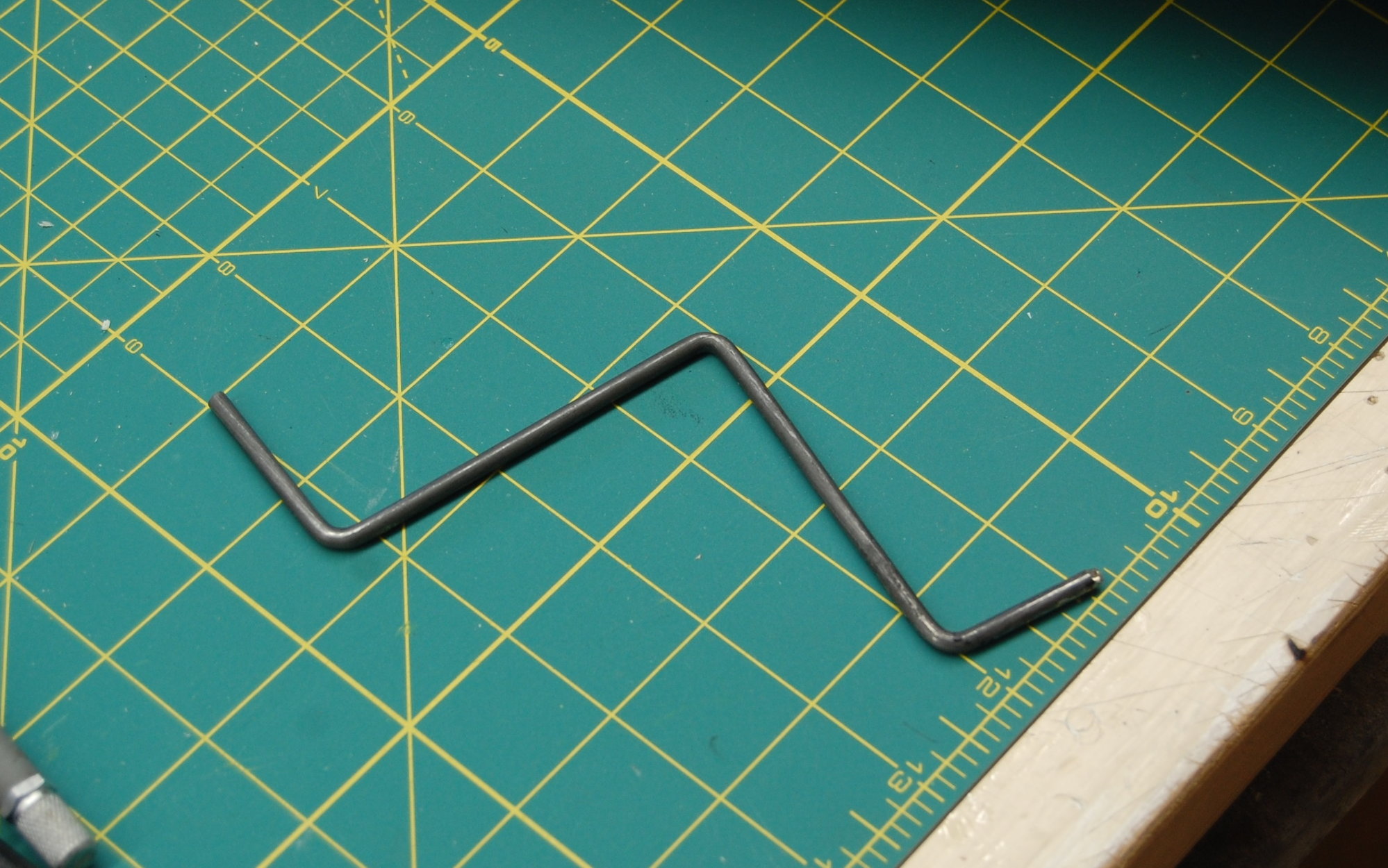
Oops, this was supposed to be a resized photo. Any way, here's a shot of the main gear. It started off life as a set for an Astrohog. it was trimmed and bent to fit.
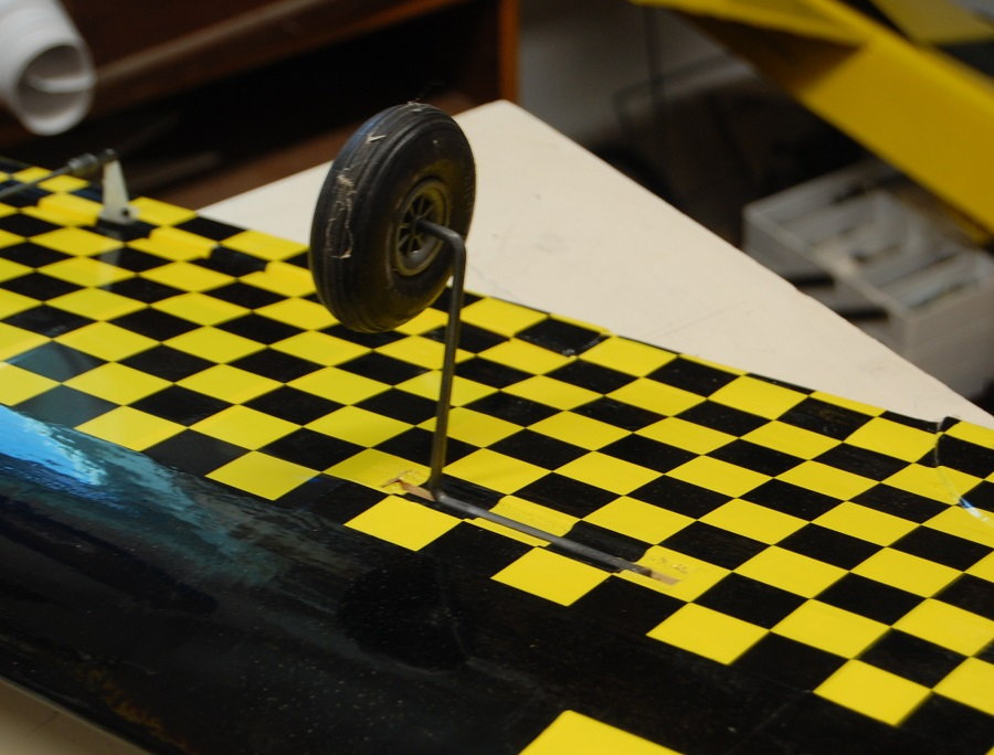
The main gear in place on the bottom of the wing. The wheels are an old set from off the shelf, hence the cobwebs. They are the correct diameter but would need to have the shafts sleeved to be usable.
Sitting on its feet for the first time. The camera angle and taper of the wing make it look as though it has a little anhedral but the wing is actually flat across the top.

Oops, this was supposed to be a resized photo. Any way, here's a shot of the main gear. It started off life as a set for an Astrohog. it was trimmed and bent to fit.
The main gear in place on the bottom of the wing. The wheels are an old set from off the shelf, hence the cobwebs. They are the correct diameter but would need to have the shafts sleeved to be usable.
Sitting on its feet for the first time. The camera angle and taper of the wing make it look as though it has a little anhedral but the wing is actually flat across the top.
06-12-2019, 03:33 PM
#100
Thread Starter
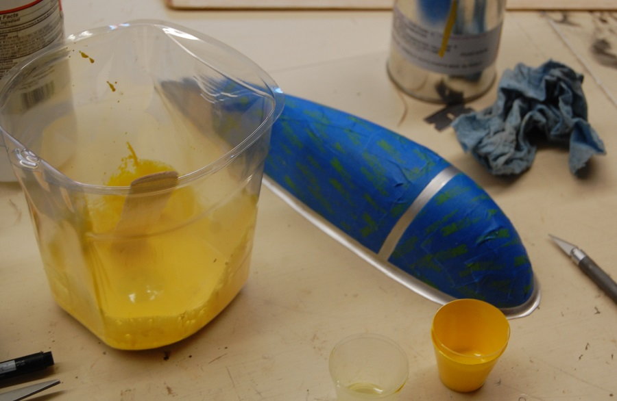
Well Michael, I have to get the canopy on first. The canopy is a Sig product. I think this one is about 12 inches long. I have seen them with much longer canopies. I sprayed the interior with silver model car paint and them masked the outside with good quality tape.
The color is some Nason catalyzed urethane that i had mixed up for an earlier project. It is a good thing that it fit for this project because I had to buy a one pint minimum. I mixed up one ounce and probably only sprayed half of that.
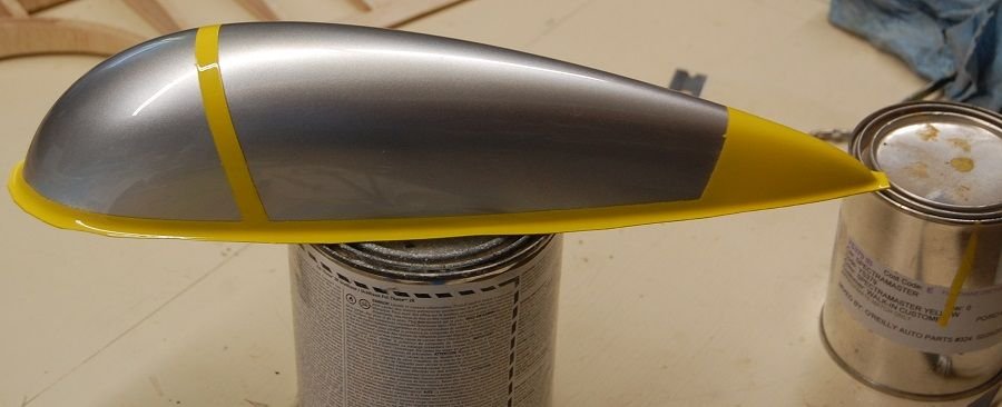
Here is the painted canopy. Automotive paint is pricey but it is tough and it can produce a beautiful gloss finish. I used an old (and cheap) Cambell Housefeld automotive touch up gun to shoot the paint.
I sanded away the silver for the glue joint and added some sheet balsa for added security in gluing down the canopy. I also trimmed away some of the covering on top of the fuselage to get a balsa to balsa joint.
The canopy is mounted In addition to thick CA used for the balsa joints the canopy is glued around the perimeter with Pacer canopy glue. it definitely needs a yellow spinner.
The canopy is a Sig product. I think this one is about 12 inches long. I have seen them with much longer canopies. I sprayed the interior with silver model car paint and them masked the outside with good quality tape. The color is some Nason catalyzed urethane that i had mixed up for an earlier project. It is a good thing that it fit for this project because I had to buy a one pint minimum. I mixed up one ounce and probably only sprayed half of that.
Here is the painted canopy. Automotive paint is pricey but it is tough and it can produce a beautiful gloss finish. I used an old (and cheap) Cambell Housefeld automotive touch up gun to shoot the paint.
I sanded away the silver for the glue joint and added some sheet balsa for added security in gluing down the canopy. I also trimmed away some of the covering on top of the fuselage to get a balsa to balsa joint.
The canopy is mounted In addition to thick CA used for the balsa joints the canopy is glued around the perimeter with Pacer canopy glue. it definitely needs a yellow spinner.