


TF Beechcraft Bonanza F33A Build
 12-03-2019, 01:44 AM
#501

Thread Starter
 12-03-2019, 01:46 AM
#502
Thread Starter

 12-03-2019, 10:32 AM
#504
Thread Starter
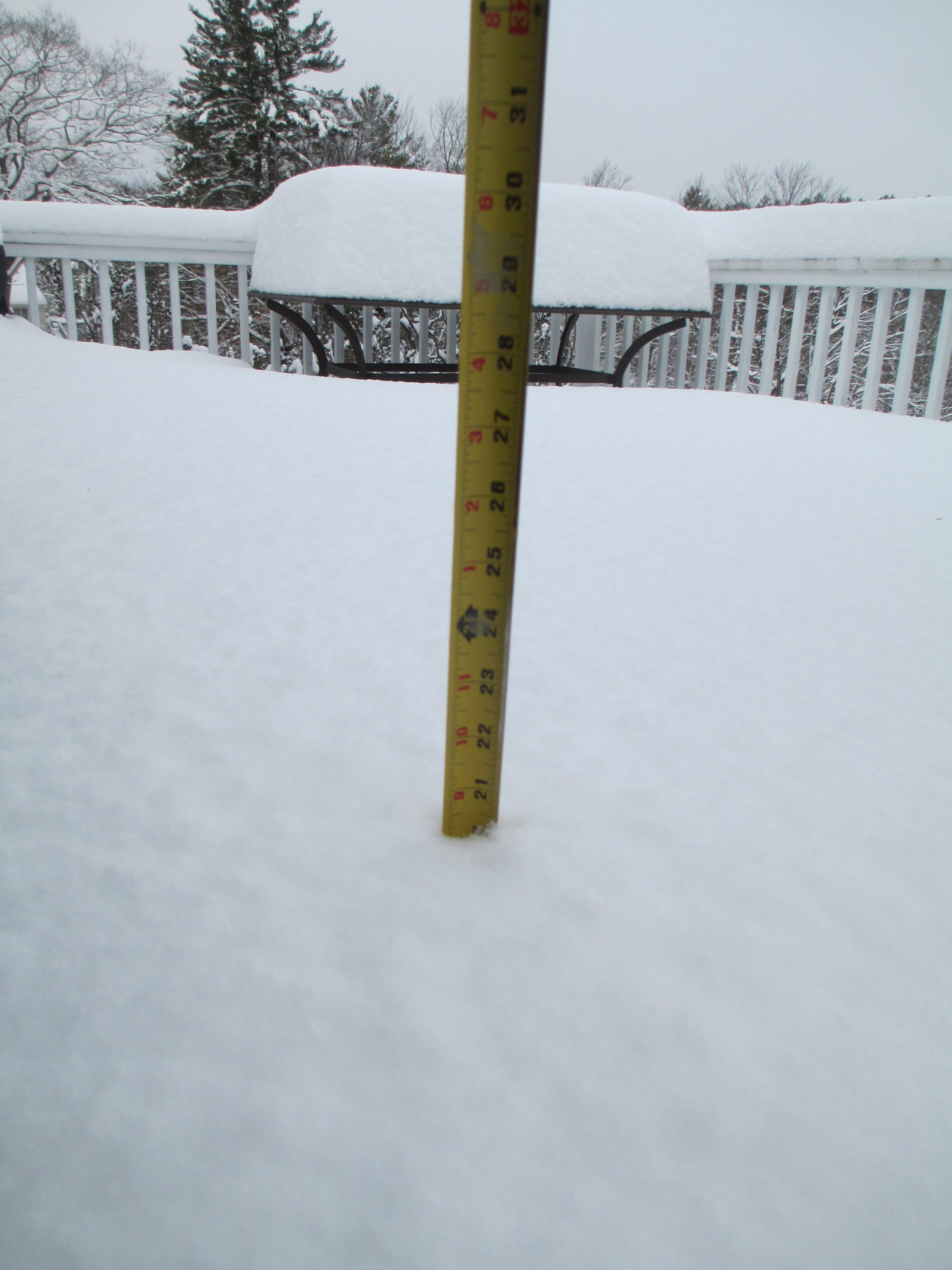
It finally stopped snowing after two days!
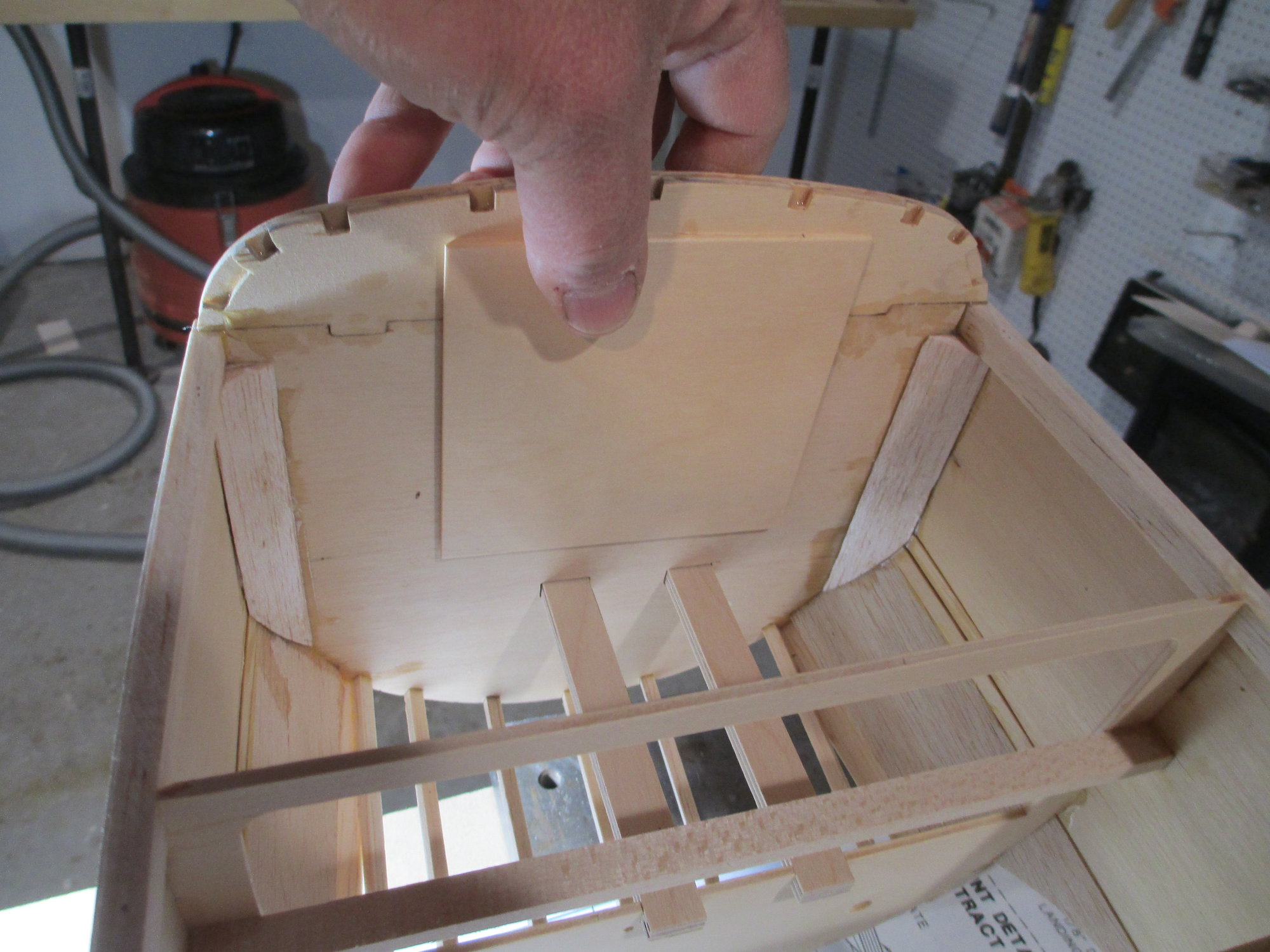
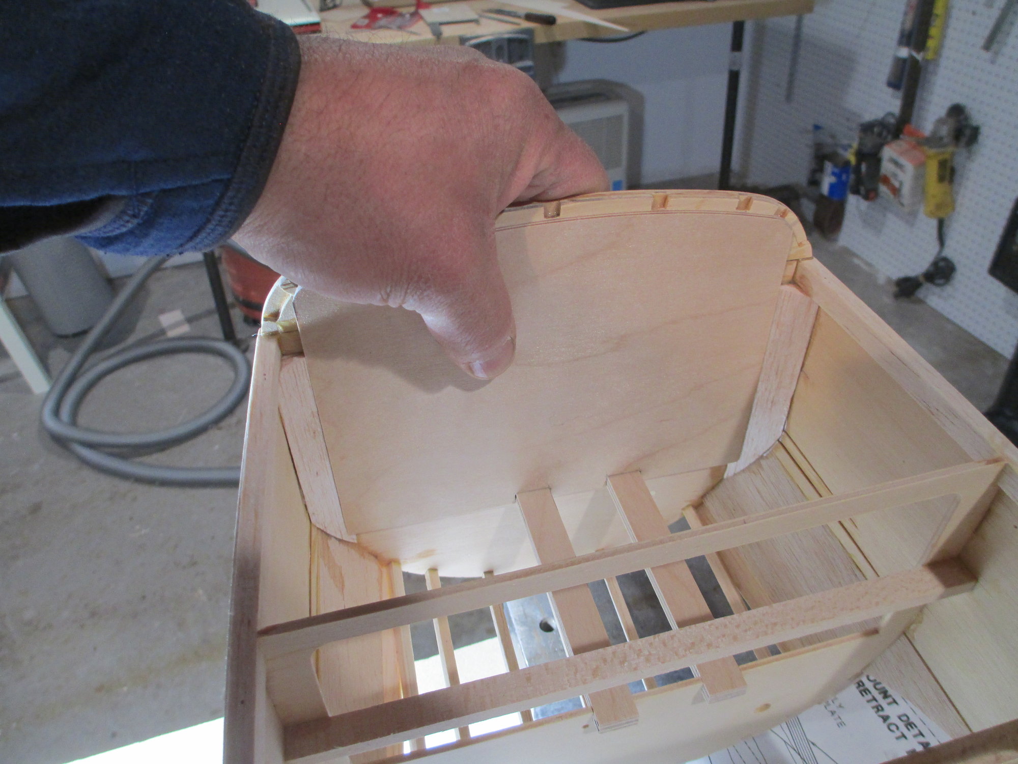
I'm holding the supplied 1/8" plywood firewall doubler against the inside of the firewall. I think I can improve on its strength and thickness.
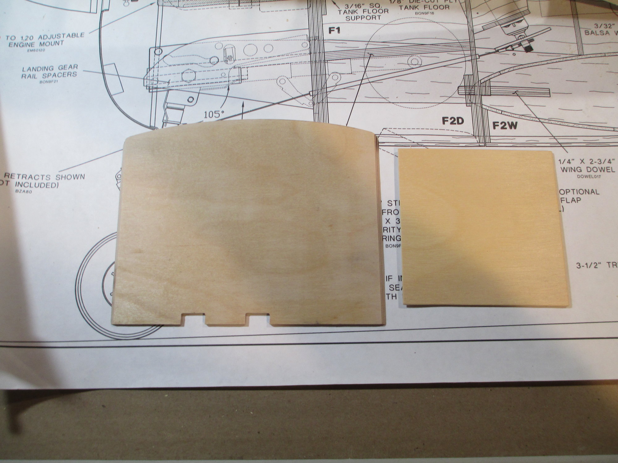
On the left is the new and improved firewall doubler. It is larger and thicker which will give the firewall a 3/8" overall thickness. It will also give better support for both front landing gear rails.
Time to mix-up some epoxy...
Last edited by VincentJ; 12-03-2019 at 10:36 AM.
12-03-2019, 12:32 PM
#505
On the Top Flite Cessna 182 kit all the wood in the landing gear area was liteply so I replaced it with real plywood. Did Top Flite do the same with the Bonanza kit?
Its a good thing it stopped snowing a few more inches and you might have to breakout the snow blower! To ad insult to injury it was 57 degrees here when I came back from lunch.
Its a good thing it stopped snowing a few more inches and you might have to breakout the snow blower! To ad insult to injury it was 57 degrees here when I came back from lunch.
12-03-2019, 12:47 PM
#506
Thread Starter
Mike, the plywood used in this Top Flite kit is real ply not the "fat free" stuff! lol I have been pretty impressed with the quality of the wood supplied.
12-03-2019, 01:01 PM
#507
Last edited by FlyerInOKC; 12-03-2019 at 01:05 PM. Reason: Add picture
12-03-2019, 02:14 PM
#508
Thread Starter
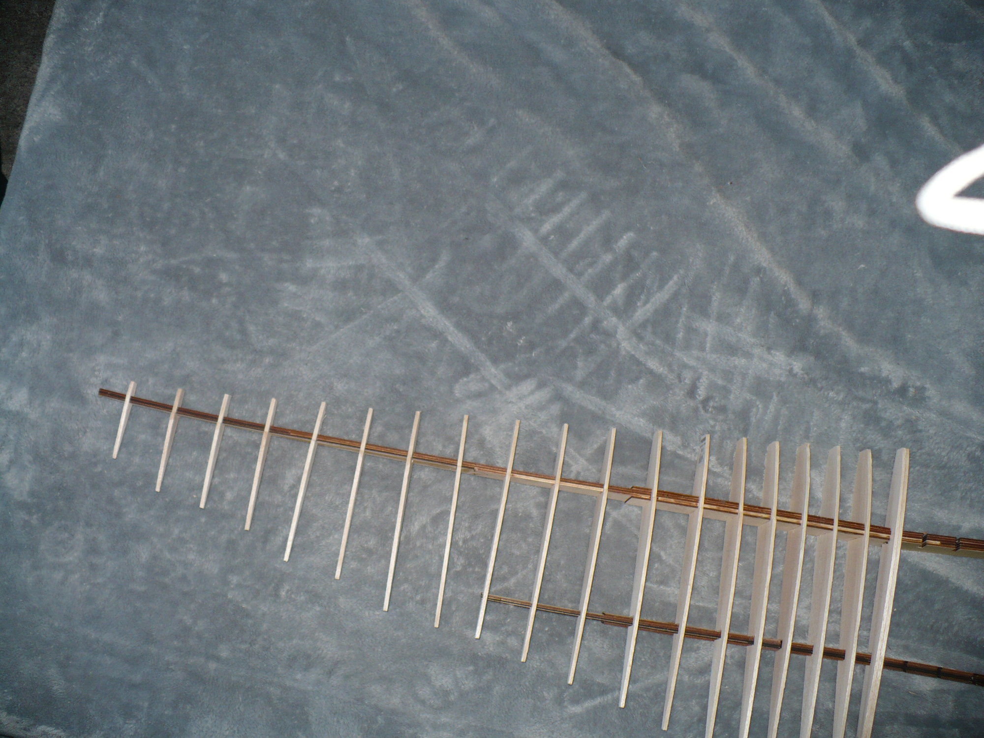
That is good to hear. I don't have anything against liteply when used appropriately but supporting landing gear or say in a firewall is not some of them. When I started modifying the Dick Katz 1/5th scale Ryan SC I did substitute some liteply for plywood in his over built design. As an example he used 3/16" balsa for the wing ribs for a 84" tapered wing. Look closely at the picture and see how thick the main spar is and it has a secondary spar too boot. The RCM Navion by Walter Musciano was similar in design but not quite as over built just close to it.
12-03-2019, 02:20 PM
#509
Thread Starter
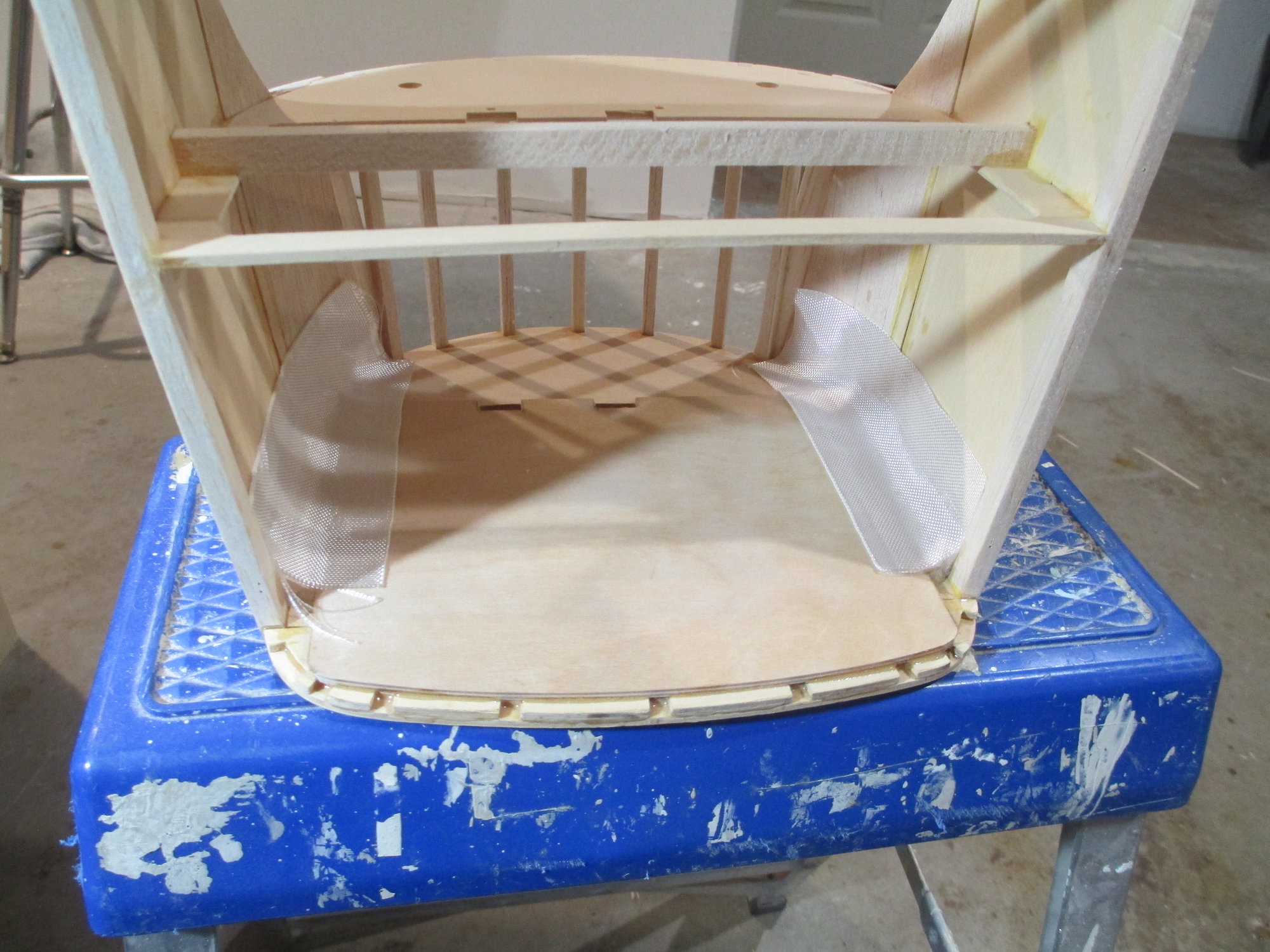
I really wanted to tie in the firewall to the sides of the fuselage. Gas engines are known to vibrate more than glow engines, so I used fiberglass strips to get the job done.
This is the first of two coats, it will also serve to fuel proof the area.
12-05-2019, 01:31 AM
#511
Thread Starter
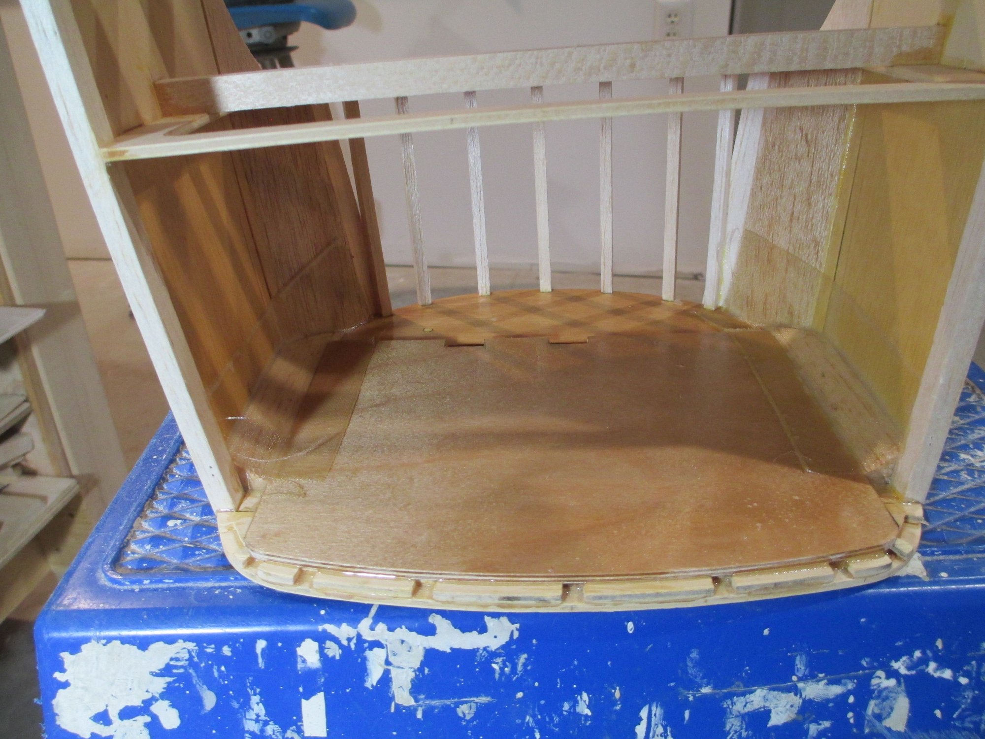
Second and final coat of Resin applied over the fiberglass strips. The firewall is nicely tied into the fuselage now.
Last edited by VincentJ; 12-05-2019 at 08:59 AM.
12-05-2019, 03:35 AM
#512
Thread Starter
Interesting clip of a Bonanza cutaway at the Beechcraft Heritage Museum in Tennessee. A good way to end up with an accurate scale model is to see what it looks like underneath...
https://beechcrafthm.org/index.html
https://beechcrafthm.org/index.html
Last edited by VincentJ; 12-06-2019 at 03:24 AM.
The following users liked this post:
Skypoint (11-19-2022)
 12-05-2019, 07:57 AM
#515
If you want a full size short kit or one that is reduced to 90% of the original Ziroli design you can get one here:
LDS - Laser Design Services
Contact: [email protected]
LDS - Laser Design Services
Contact: [email protected]
12-05-2019, 01:01 PM
#516
One thing I have been meaning to share with you Vince but I keep forgetting to mention it. When I fuel proof the engine/tank compartment I like to use a Finishing Epoxy with a little color added. I go down to the local paint store with a small pill bottle and talk them out of a little latex paint pigment. It doesn't affect the epoxy except to add color. I general use black when a cowling is going to hide most of it. If you keep the pigment in a small sealed container it will last for a very long time and you don't use much of it at all.
12-06-2019, 01:34 AM
#517
Thread Starter
One thing I have been meaning to share with you Vince but I keep forgetting to mention it. When I fuel proof the engine/tank compartment I like to use a Finishing Epoxy with a little color added. I go down to the local paint store with a small pill bottle and talk them out of a little latex paint pigment. It doesn't affect the epoxy except to add color. I general use black when a cowling is going to hide most of it. If you keep the pigment in a small sealed container it will last for a very long time and you don't use much of it at all.
12-06-2019, 05:44 AM
#518
Two fold, first it made the are fuel proof, second if a bit of the engine compartment was seen thru an air inlet/outlet it was less noticeable because it was black and would be seen as a a void, a shadow, part of an engine, or whatever else your brain tried to fill in the blank with. Its like when you install paneling next to a natural stone fireplace. It is impossible to cut the paneling perfectly to such an irregular surface. So you first paint the edge of the wall around he stone so when you cut the paneling any slight gaps show up as shadow. Black paint can hide a multitude of sins when used correctly. My wife's Uncle Eddie (a retired A&P with AA) taught us that.
12-06-2019, 08:53 AM
#521
Thread Starter
I'm working on the nose retracts Mike. Once they are in place then I can sort out the engine (position)...
Last edited by VincentJ; 12-06-2019 at 10:48 AM.
12-06-2019, 09:10 AM
#522
I haven't started my Caddell A36 yet but I see the nose retract as a challenge since the retract used in his design is long gone from the market. The closest I could find was the Robart gear designed for your kit which should work out find. Caddell sold corrugated skins for his control surfaces but none are available. I plan to over come that hurdle by using a little thicker Balsa skins and routing the grooves using my Dremel router attachment and a homemade jig. Sometimes I think the best projects are the ones that teach you new tricks.
12-06-2019, 02:51 PM
#523
Thread Starter
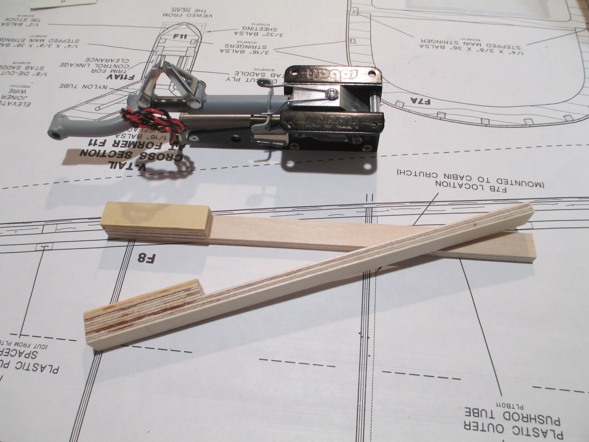
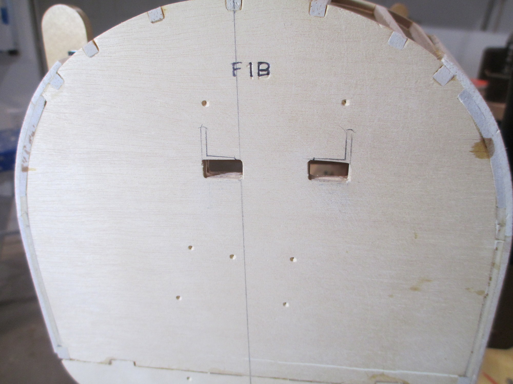
Installing the nose retract starts with assembling two 1/4" x 9/16" x 9" plywood landing gear rails. Additional 1/4" plywood spacer and 1/8" plywood spacer make up each rail. Epoxy was used in this application.
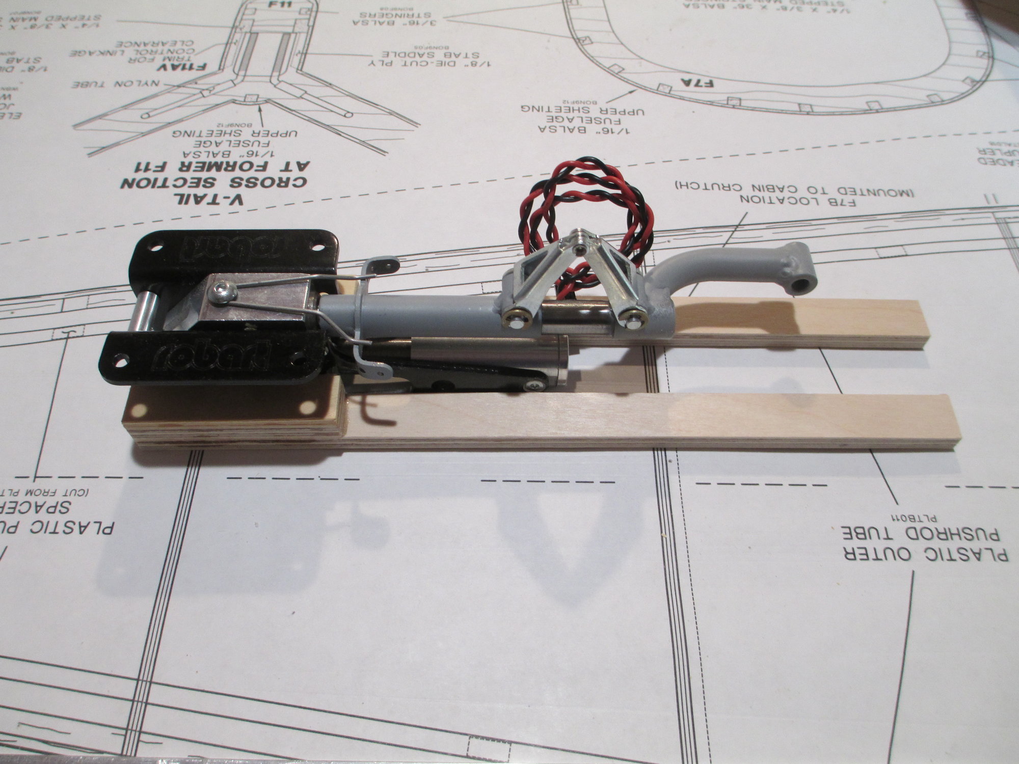
The retract was then positioned over the bottoms of each rail so the exact locations of the holes could be marked.
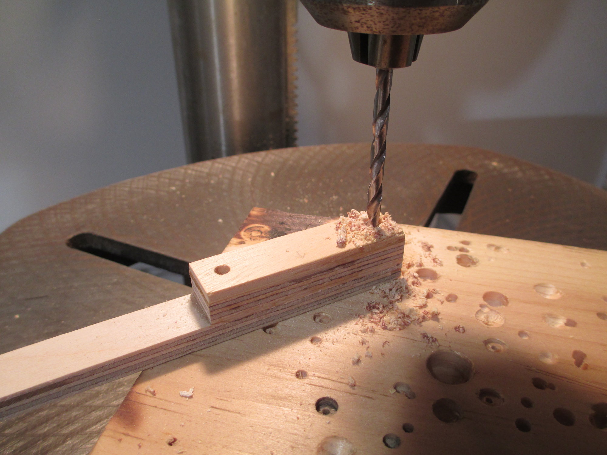
Using a drill press ensures that each of the four 5/32" holes are straight.
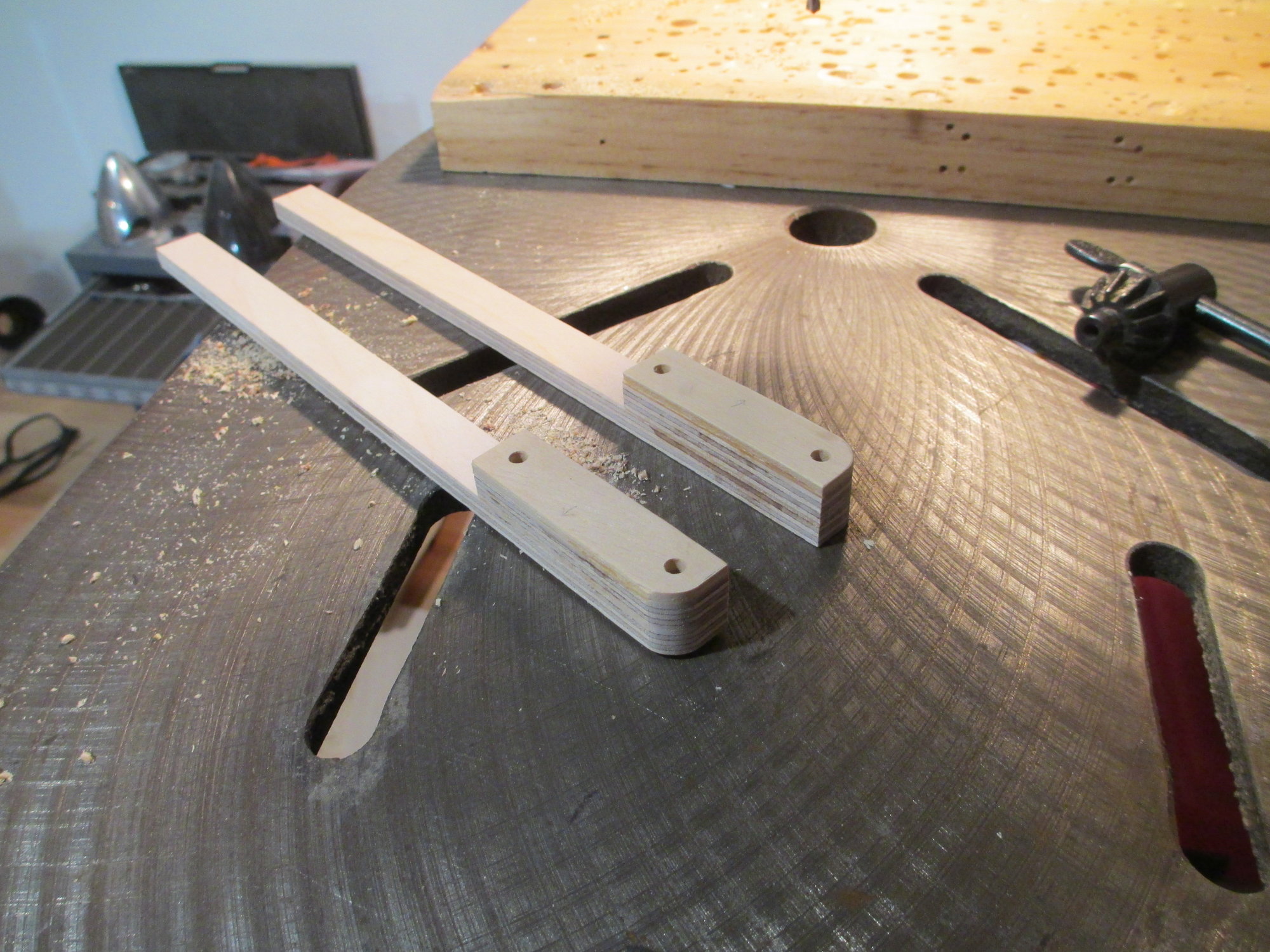
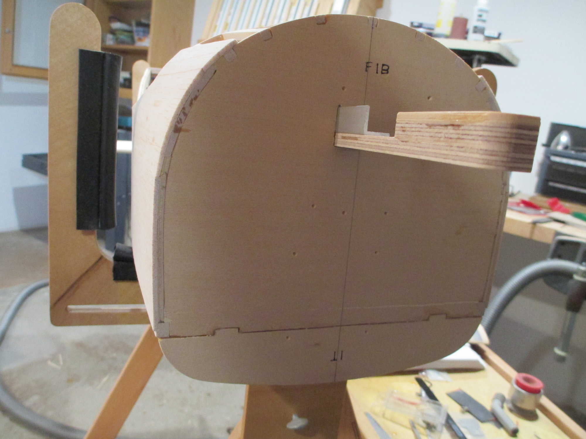
I rounded over the ends of each rail to follow the contour of the retract mounting plate.
Here's where it starts to get fun! I'm not convinced that there is adequate strength in the two plywood landing rails. With a potentially 20 pound plane, those rails could snap on not so perfect landings, so I decided to add a bit of strength by adding 1/4" aluminum angle stock to each rail. Material must be removed from the firewall for the aluminum stock.
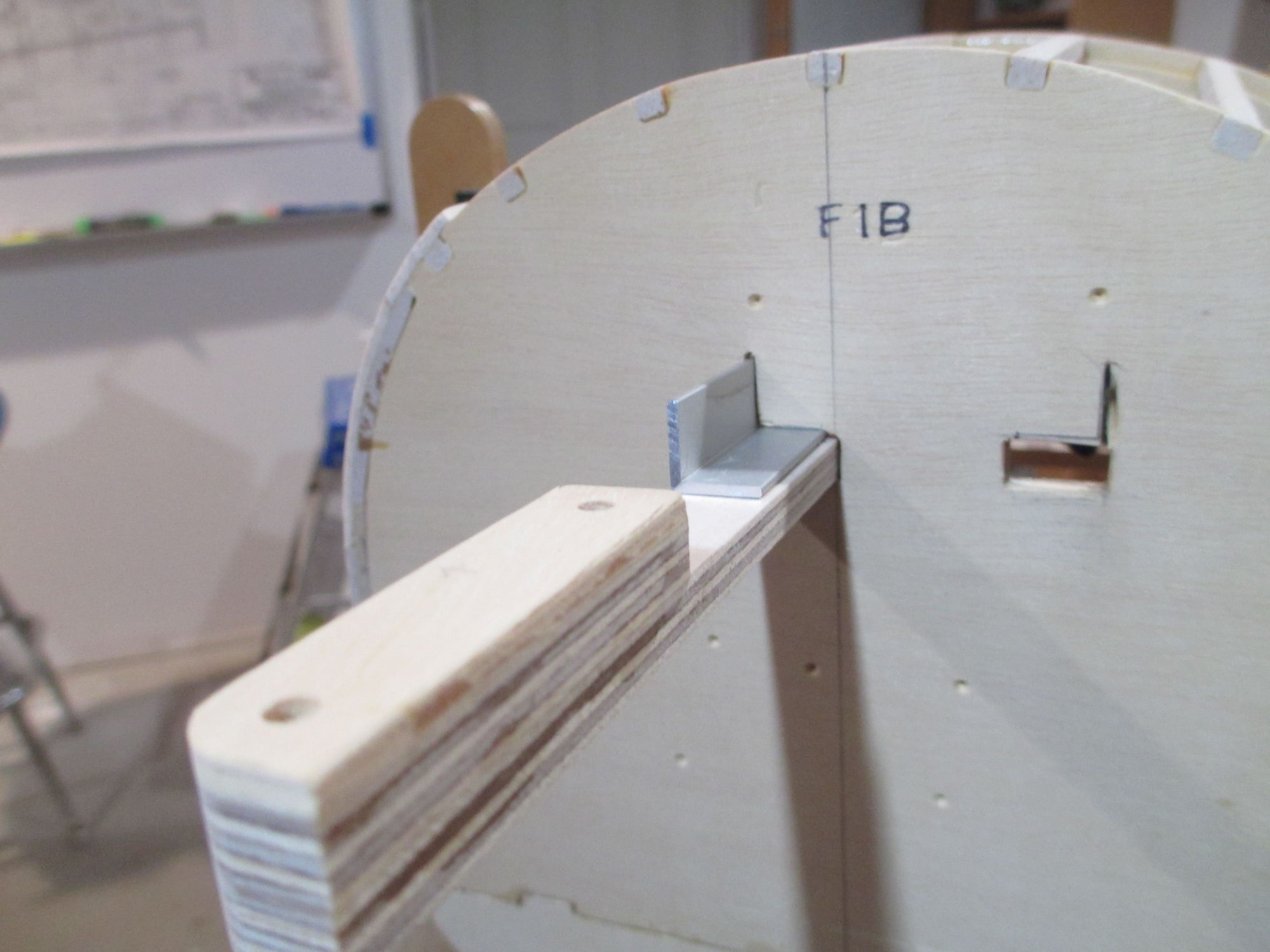
It was tedious work, but I'm happy with the fit, now for the other side...
 12-06-2019, 10:19 PM
#525
I would carry the aluminum angle right up to the front edge of the plywood rail (sandwiched between the plywood rail and mounting block and gear unit), otherwise you�ll have a stress concentration between the current end of the aluminum angle and the gear mount.
Also, maybe add some kind of gusset between rail and firewall?
Also, maybe add some kind of gusset between rail and firewall?