


TF Beechcraft Bonanza F33A Build
 10-10-2019, 06:22 PM
#301

Just a thought on the wingtips:
- I'm thinking it would have been easier to rough shape the tips to the profile in the plans and then sand it at the same time as the rest of the wing.
- When the first tip is completed to your satisfaction, make template using it as a guide so the second tip will match

 10-11-2019, 12:42 AM
#303

Thread Starter
Just a thought on the wingtips:
- I'm thinking it would have been easier to rough shape the tips to the profile in the plans and then sand it at the same time as the rest of the wing.
- When the first tip is completed to your satisfaction, make template using it as a guide so the second tip will match
Last edited by VincentJ; 10-11-2019 at 12:53 AM.
10-11-2019, 12:47 AM
#304
Thread Starter
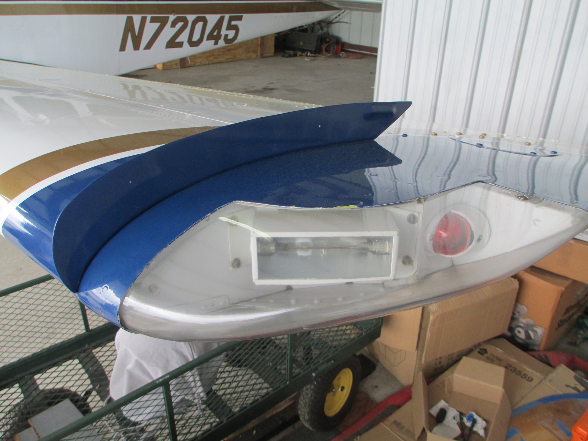
Speed, the wing tip tanks are ultra cool, but unfortunately my friend (and partner) Bob's plane didn't have them. I am trying to model this plane from the photos that I have from him. I am fortunate that he has so many photos of his plane so I can replicate it.
Last edited by VincentJ; 10-11-2019 at 12:54 AM.

 10-11-2019, 06:25 AM
#307
Vincent, did your friends airplane have the wing fence mod? While searching pictures I came across quite a few that did. You and Hydro are on the right track with being able to duplicat the tips. I did much the same with my Divergent pattern airplane. Did the first one and then made templates to do the remaining 3. Did the same technique for the stab tips. If I were selling more kits I would make molds and include fiberglass tips. Great work on the build as always.
 10-12-2019, 02:13 AM
#309
Thread Starter
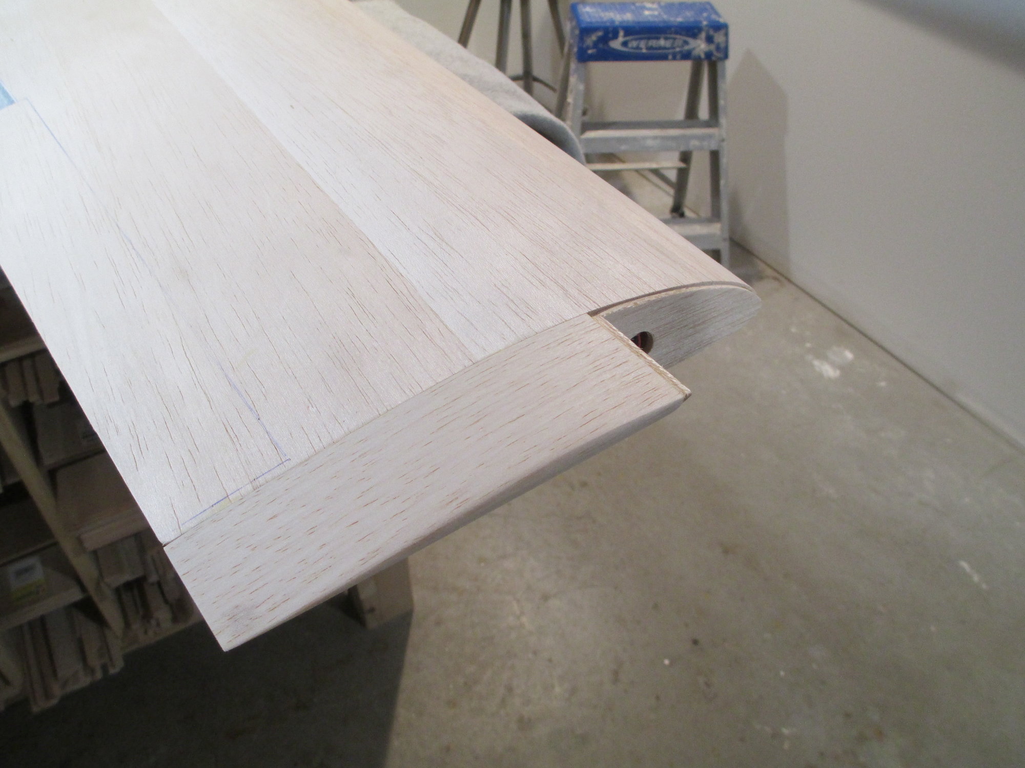
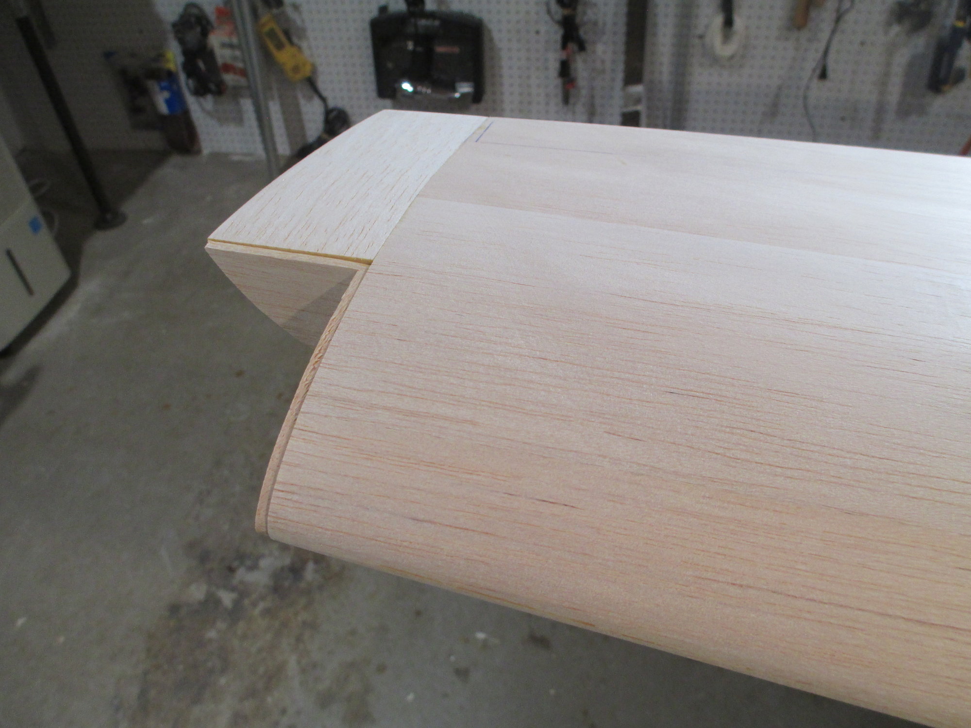
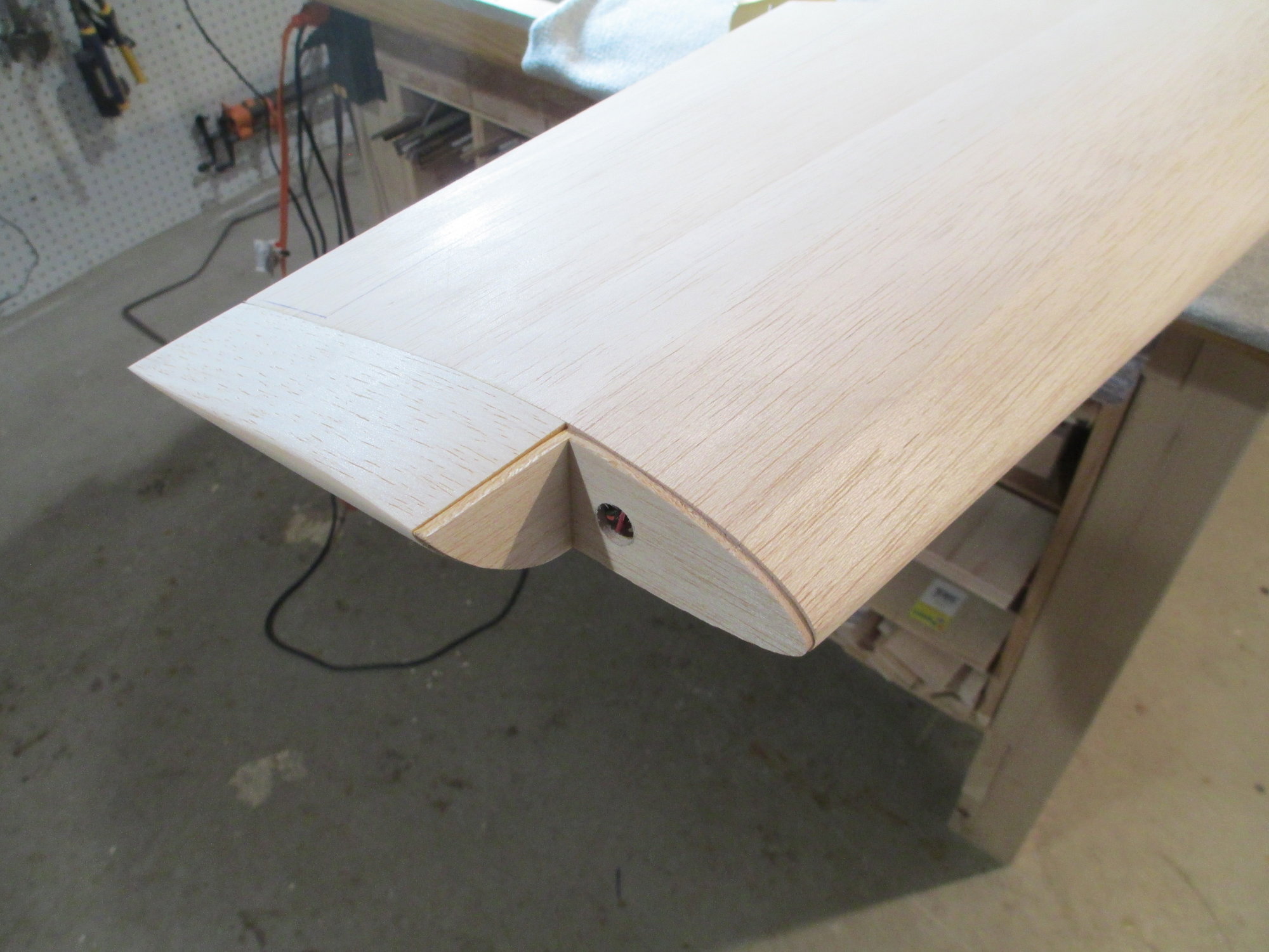
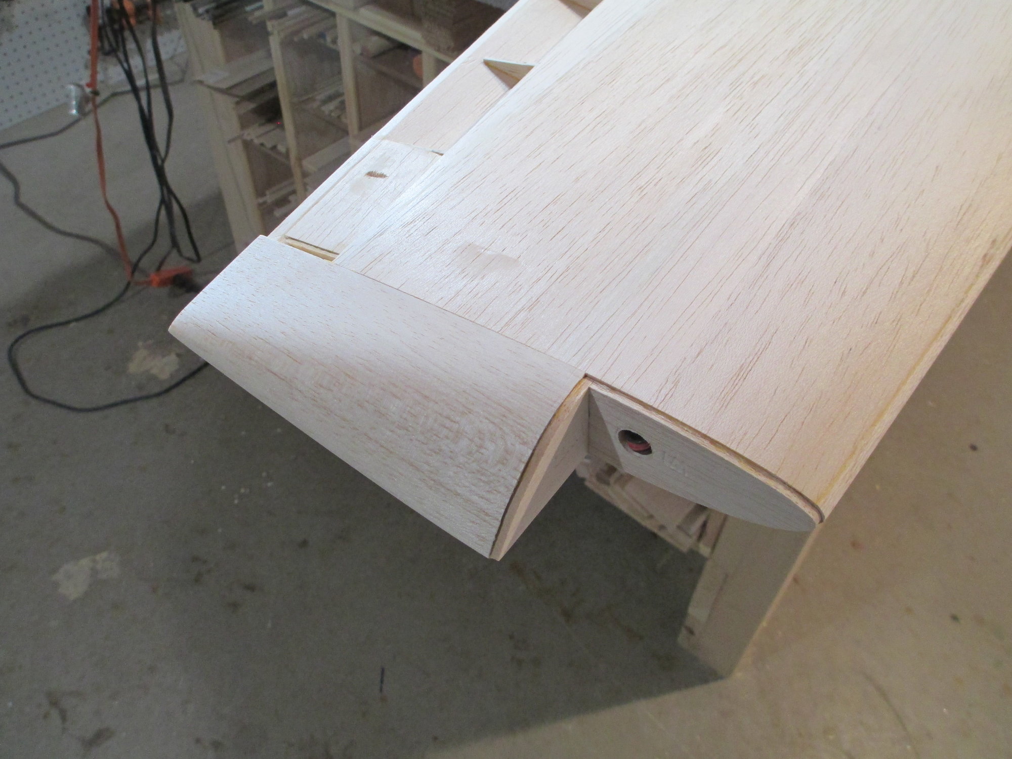
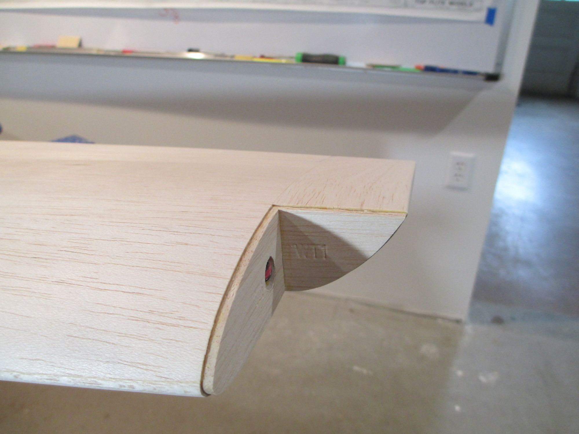
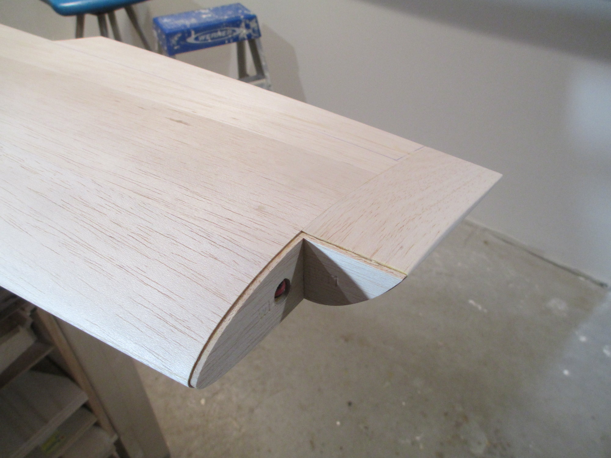
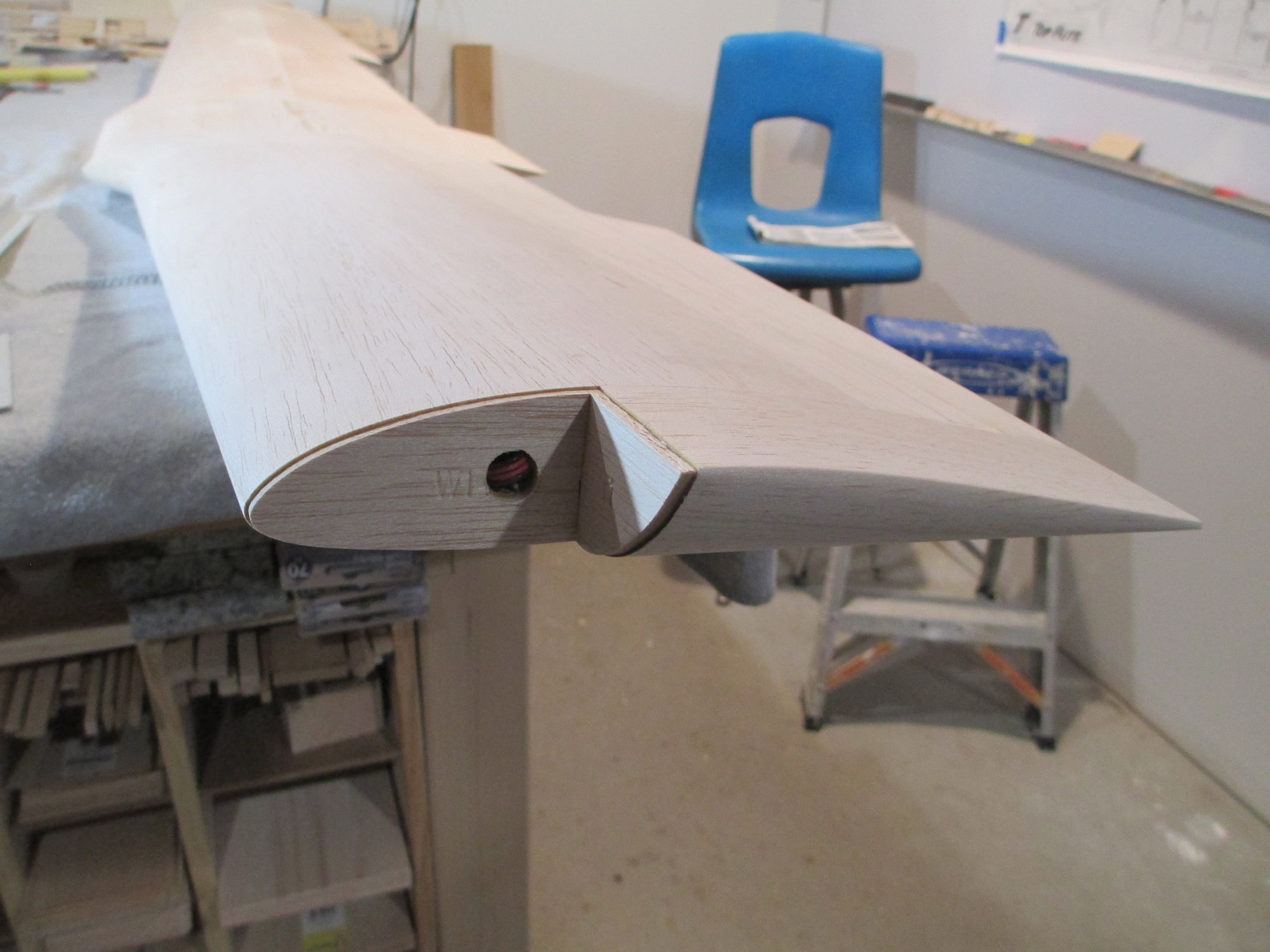
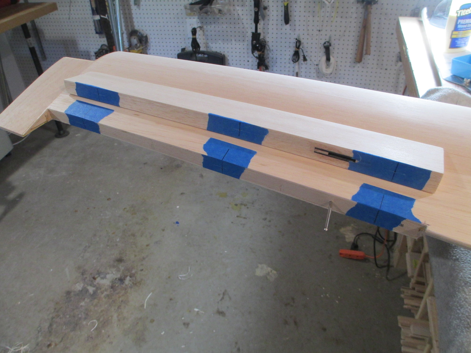
Right wing tip is roughed out. Still needs some fine tuning...
The tip was glued using Titebond. I didn't see the benefit to use epoxy here.
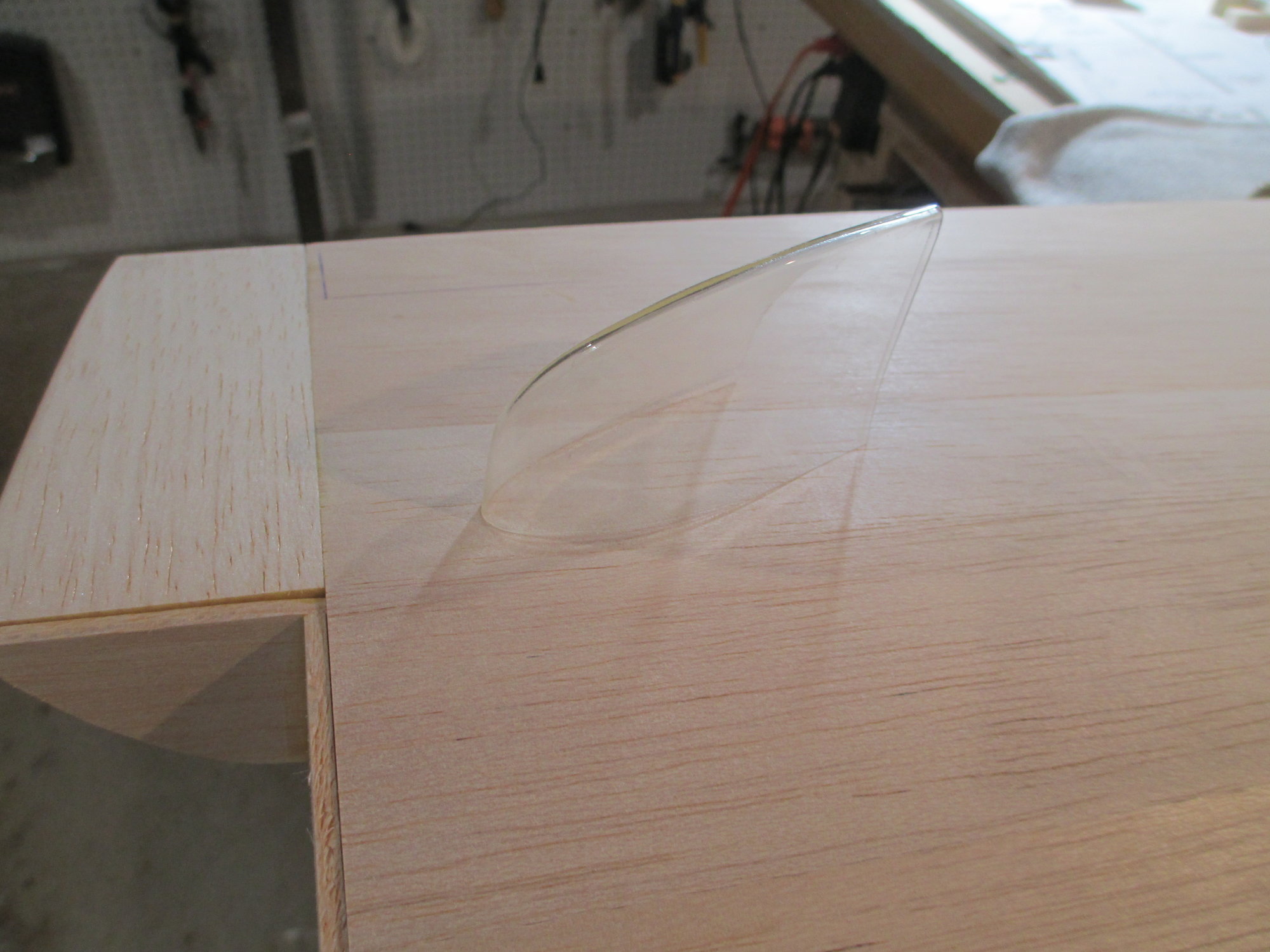
Wing tip lens trimmed to fit.
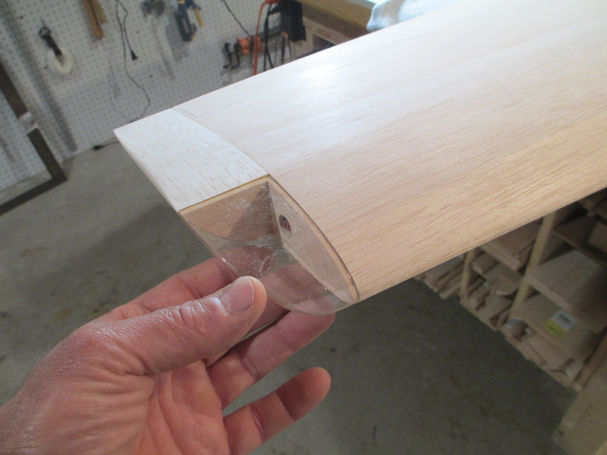
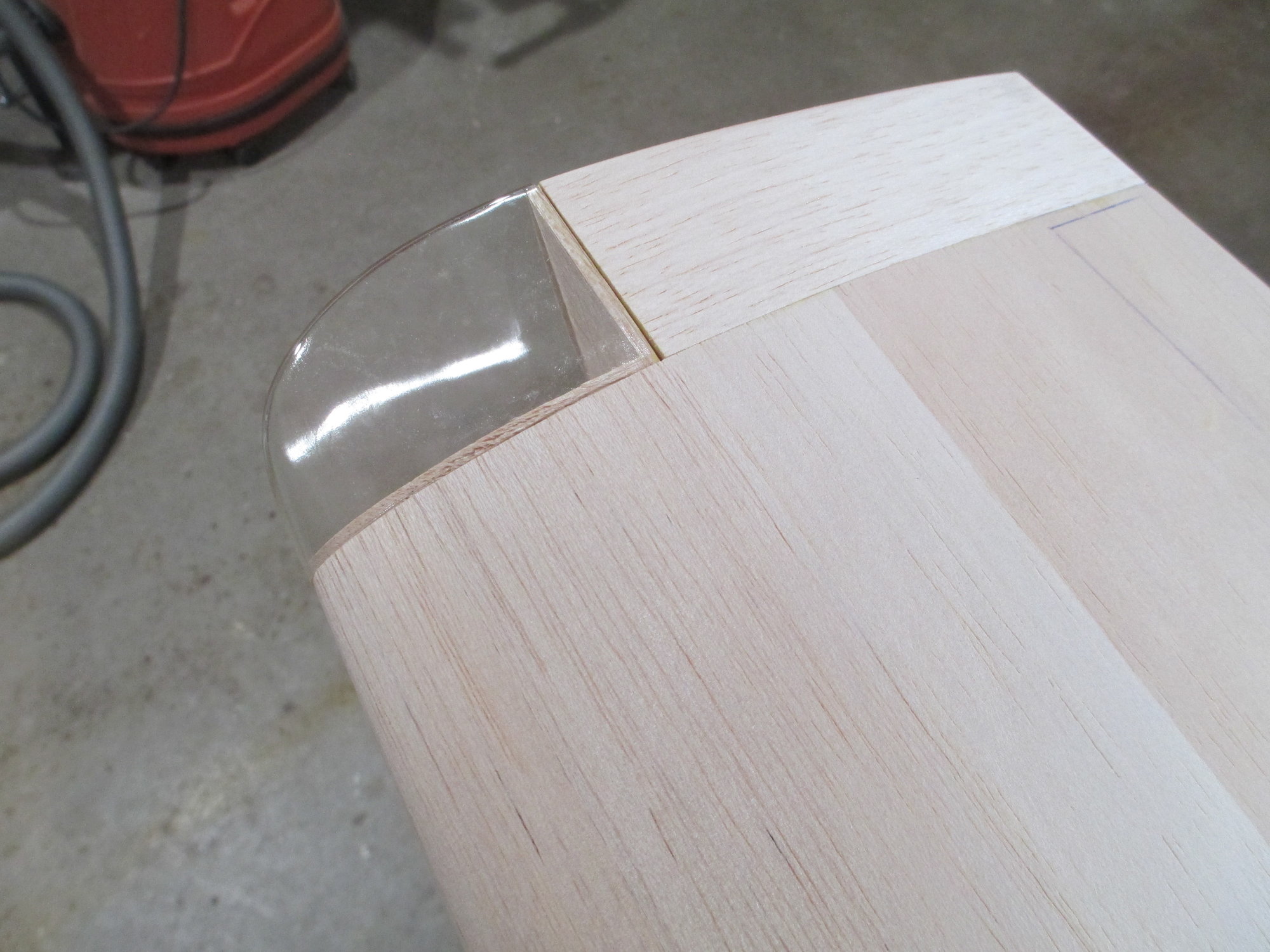
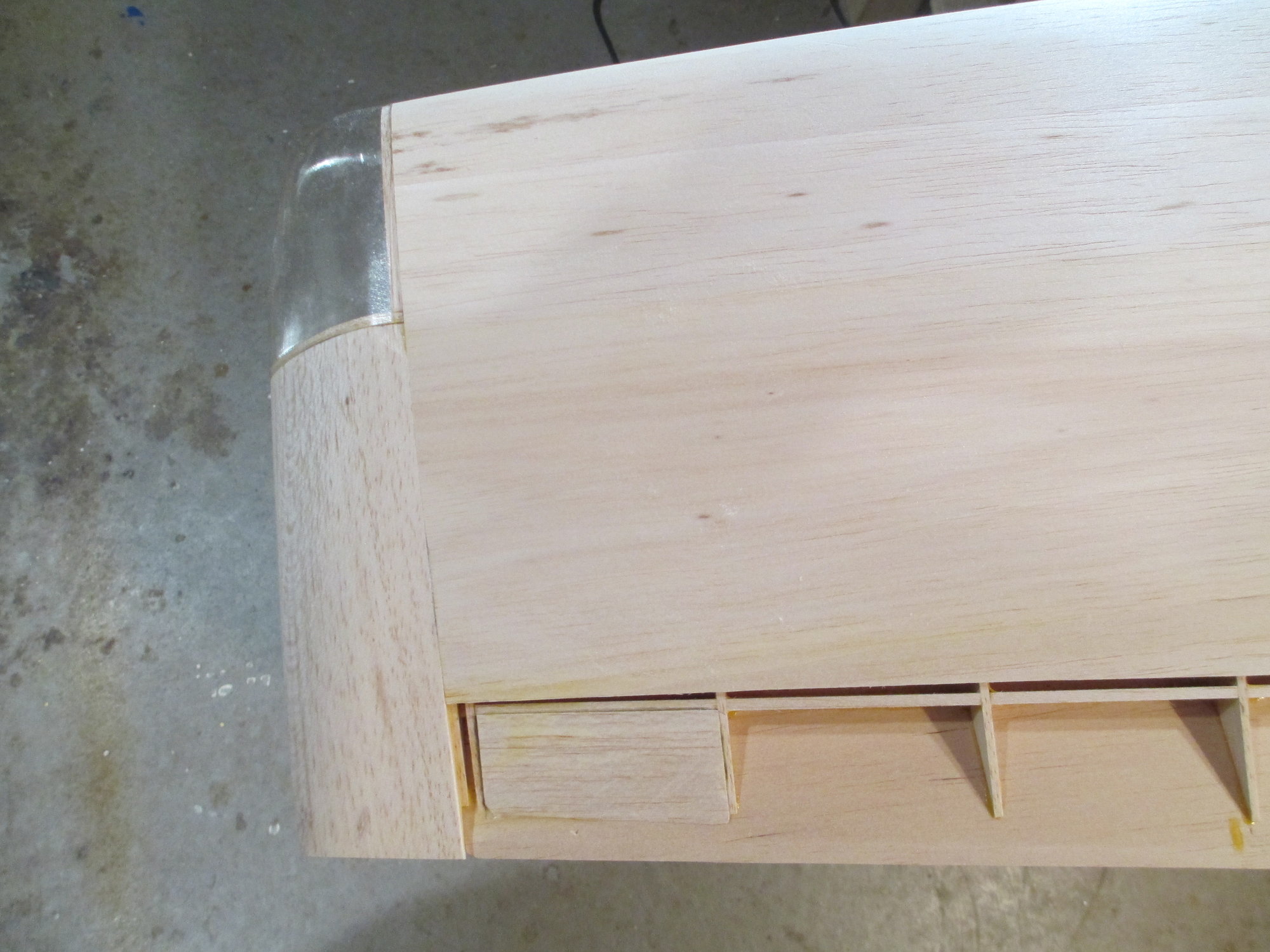
A portion of the wing tip block where the aileron abuts was left elevated. After the sheeting is applied on the aileron, I will sand to its proper height.
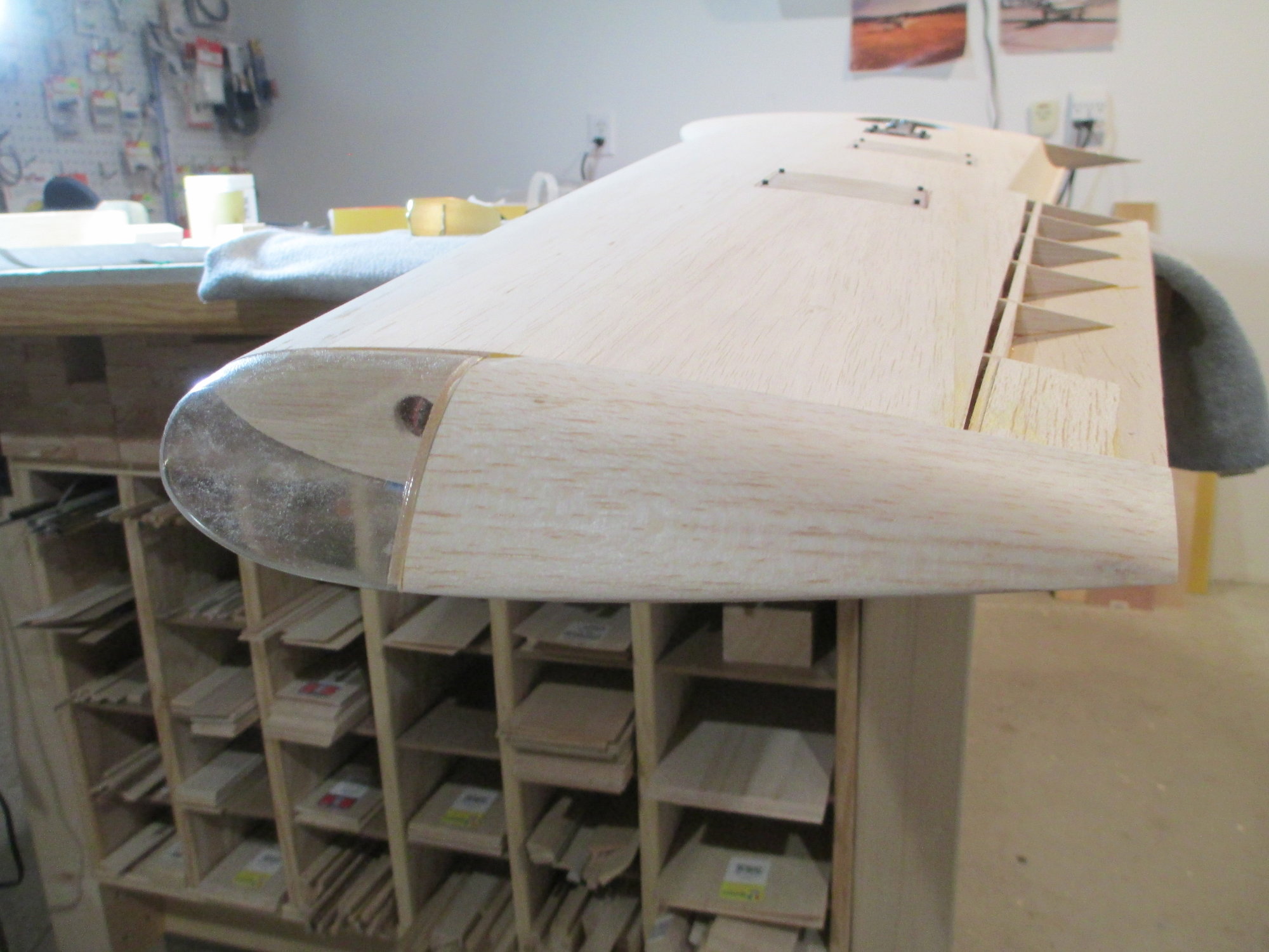
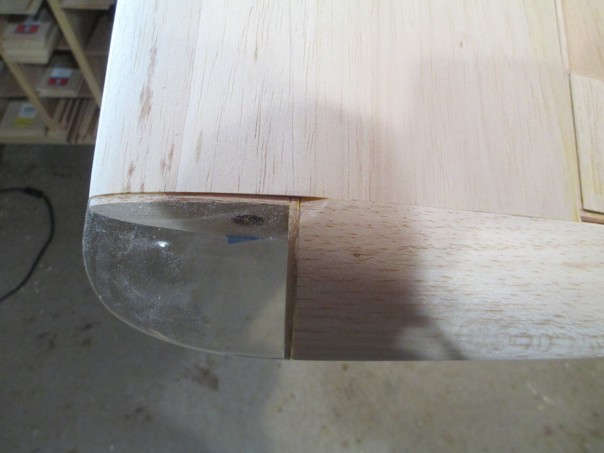
The raw wing tip block supplied was just and I mean just barely large enough to fit. My problem was that one corner of the block was slightly crushed. Sorry Bob, looks like I'm going to have to use some wood filler.
 10-12-2019, 10:34 AM
#311
Thread Starter
It's finally time to cut the ailerons free from the wing panels. I've been waiting quite some time to do this, but other tasks had to be completed beforehand. I am anxious to get the aileron Rotary Drive System (RDS) installed and operational...

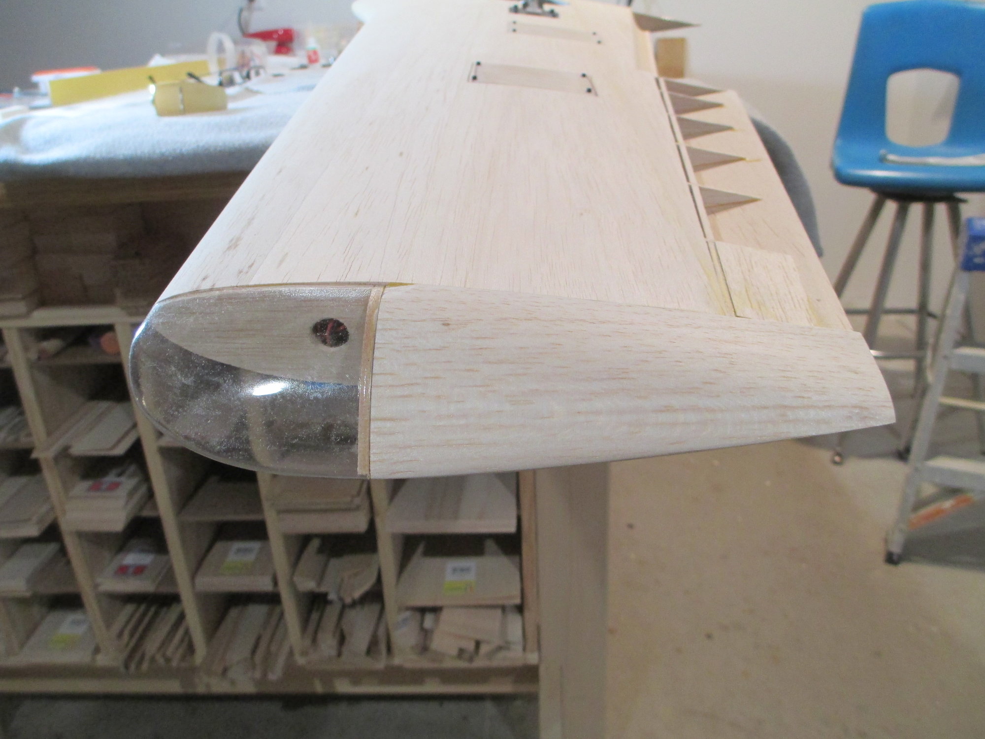
Time to free the aileron from the wing.

The cut went as planned. This time it was a very easy straight cut.
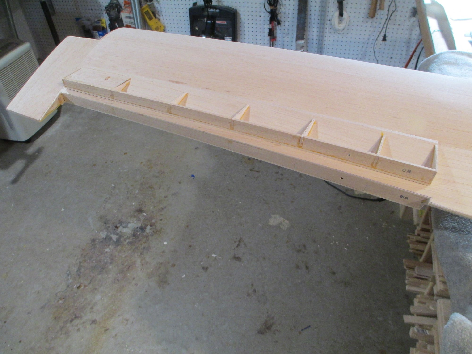
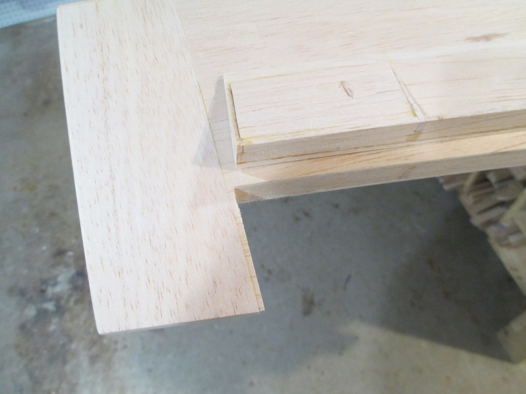
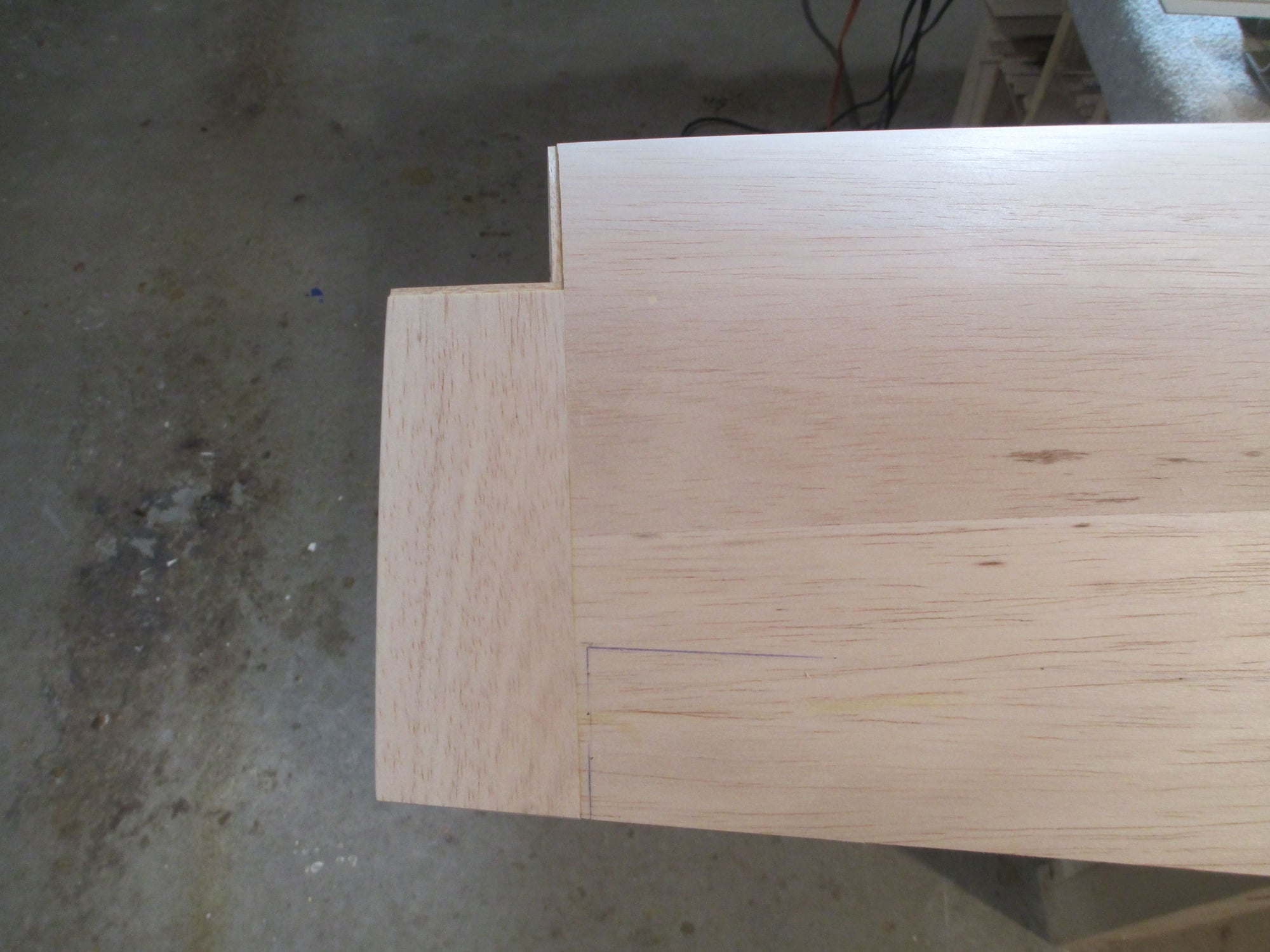
You can see why I glued the wing tip in place before I separated the aileron. That last thin rib would of snapped off if I had bumped it...
Time to free the aileron from the wing.
The cut went as planned. This time it was a very easy straight cut.
You can see why I glued the wing tip in place before I separated the aileron. That last thin rib would of snapped off if I had bumped it...
10-12-2019, 11:17 AM
#312
Thread Starter
OK, thought you guys needed a treat, so free up about 11 minutes and go pop some popcorn and enjoy...
https://www.youtube.com/watch?v=yrFt...WyaWpGKIU9KdAo
https://www.youtube.com/watch?v=yrFt...WyaWpGKIU9KdAo
10-13-2019, 01:58 PM
#313
Thread Starter
This next portion of the build some of you may find particularly interesting, I know Bob will... So maybe I need to back-up and explain... a few months ago Bob had approached me and asked if I would be interested in partnering with him on a Bonanza build. He explained that it was important to him that this project duplicate a F33A Beechcraft Bonanza that he had once owned and flew. I was in 100% but on one condition, that we build this plane to enter in various shows and competitions. When I mentioned that to him his eyes lit up and I could see he was excited about the prospect...so was I.
Trying to keep this plane as scale as I could, I wanted to have the external aileron linkages disappear. I researched how this could be accomplished and settled on the Rotary Drive System (RDS). This is by no means new technology, as this method of moving control surfaces has been around quite a while and has been used a lot by slope soaring enthusiasts. This is however something new for me, and if I don't get this to work...well let's not go down that road!
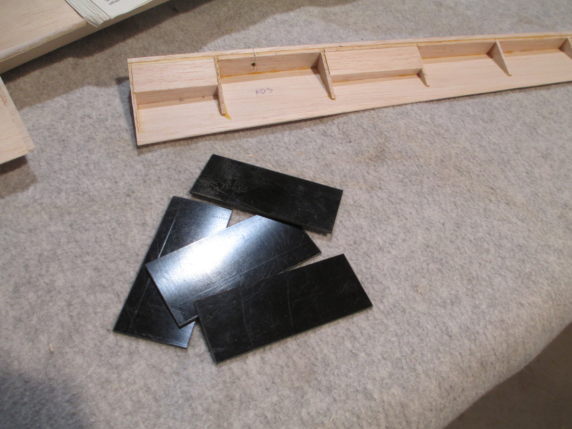
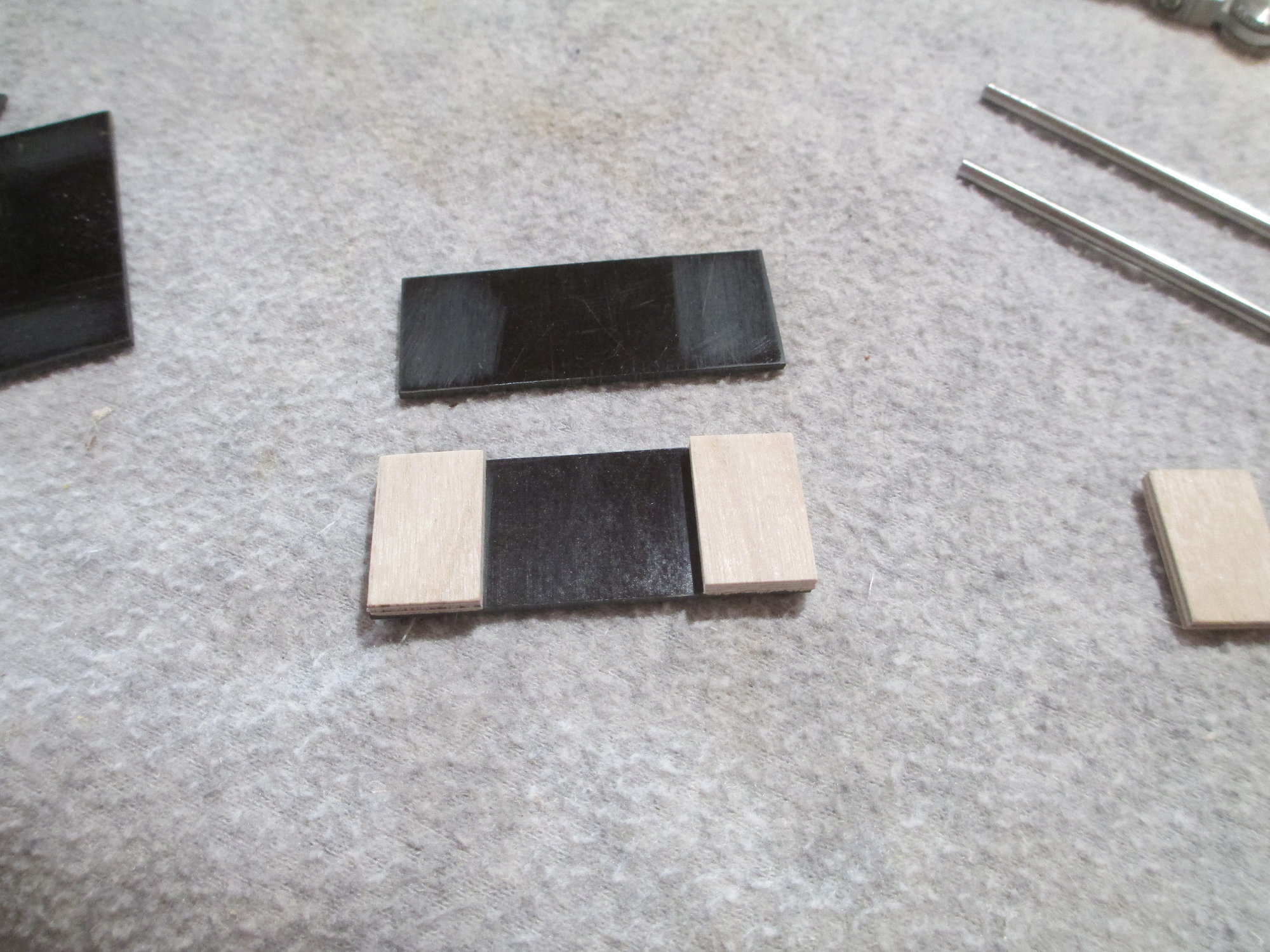
The process starts with four rough cut pieces of plastic laminate. Bob donated the laminate for this project. They will become the top and bottom of the RDS pocket.
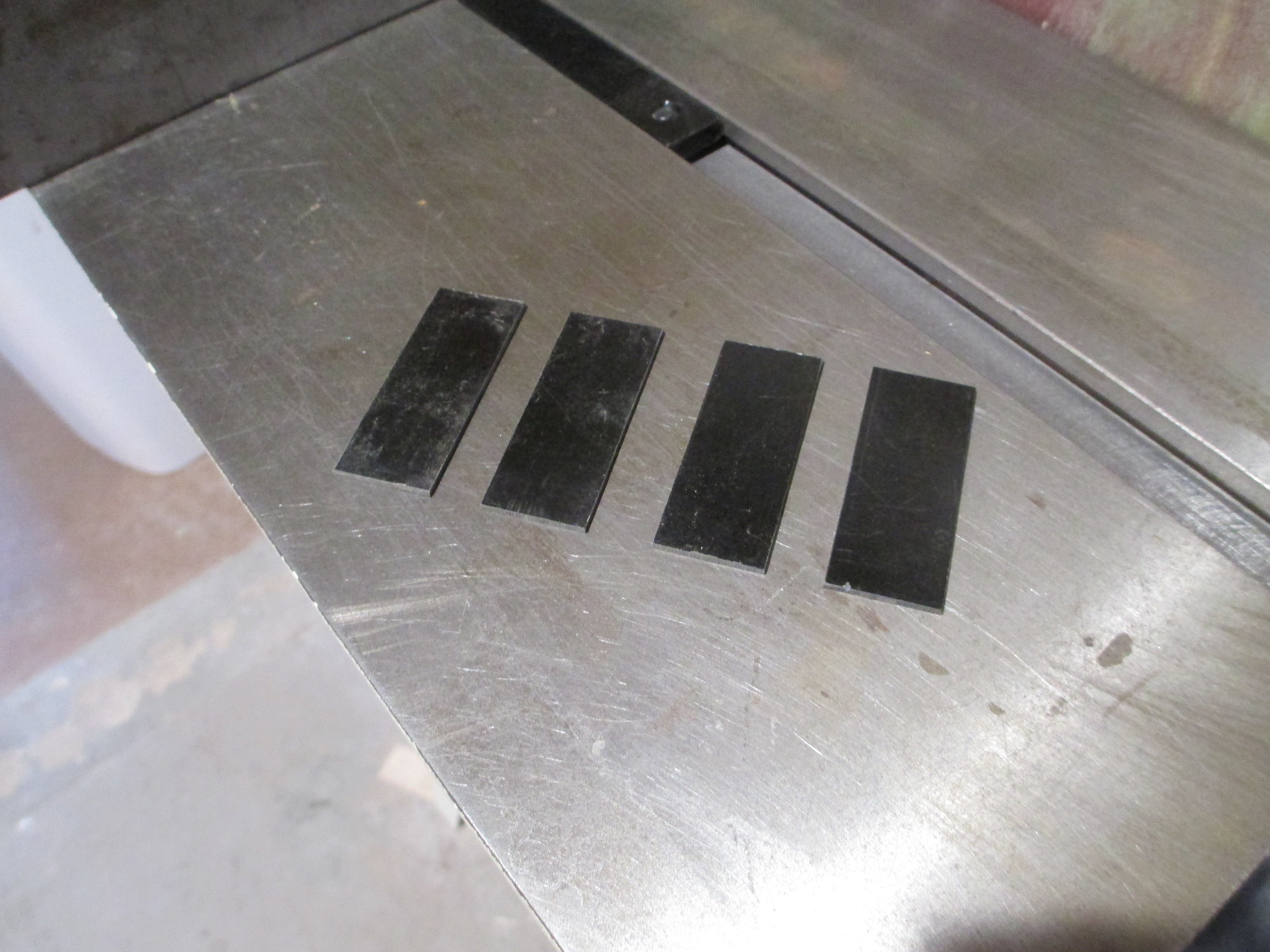
Each of the four pieces were cut to their exact sizes (3/4" x 2").
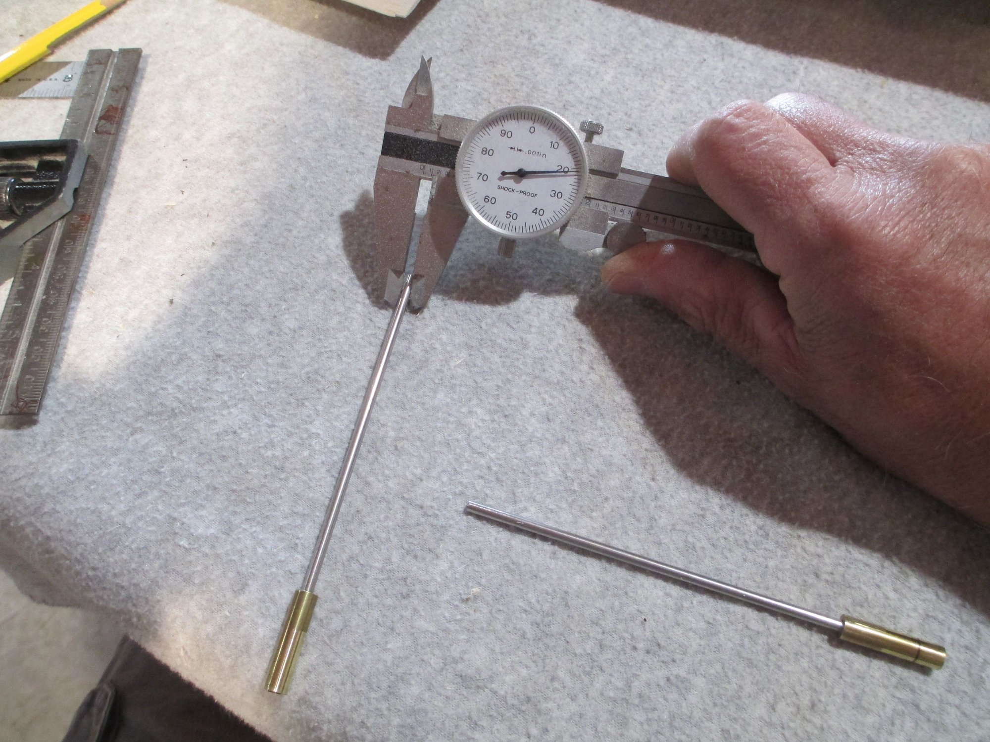
The stainless steel drive shaft was measured using a dial caliper. These drive shafts were custom made just for this project...
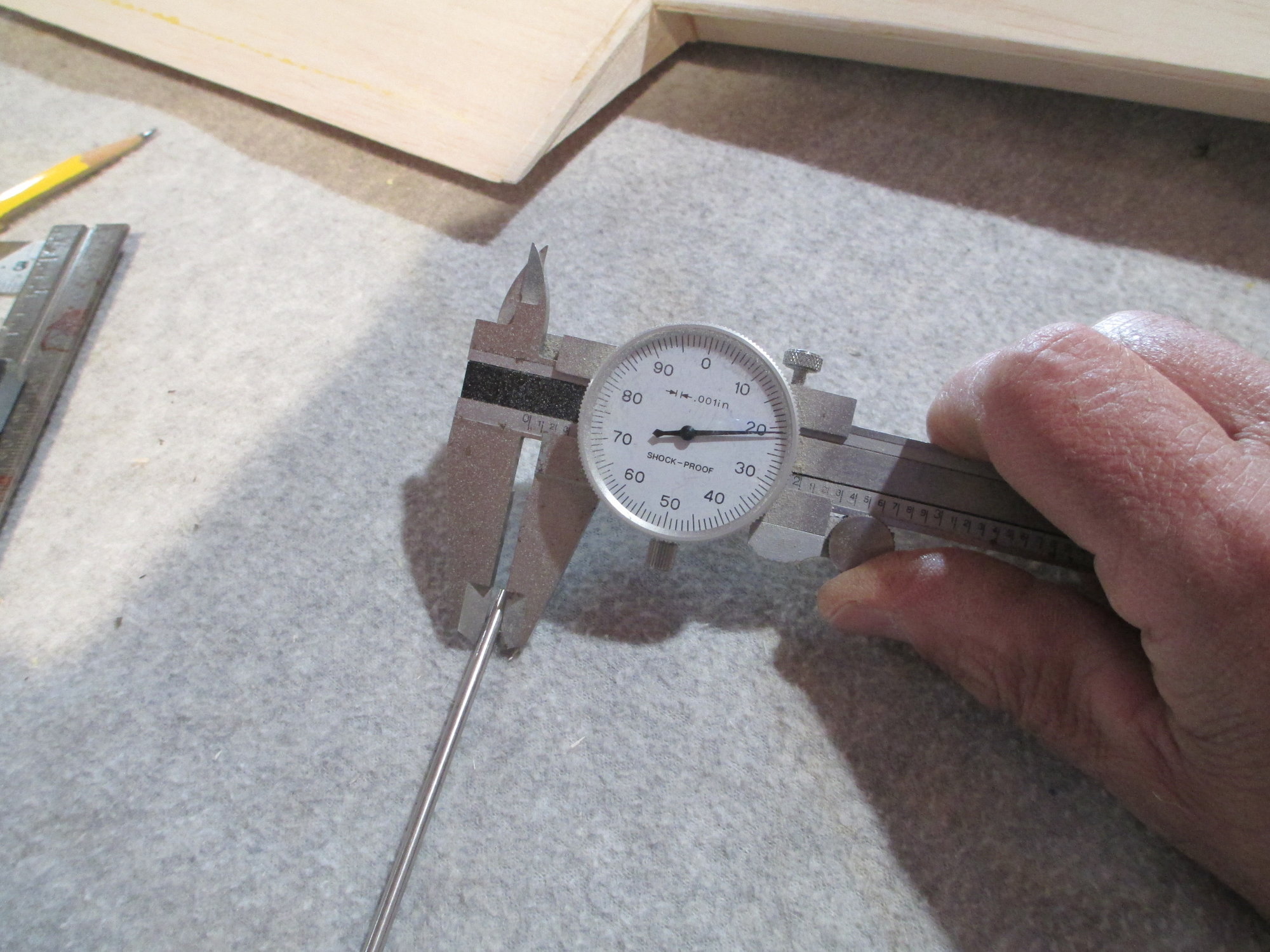
Note the dimension on the caliper.121".
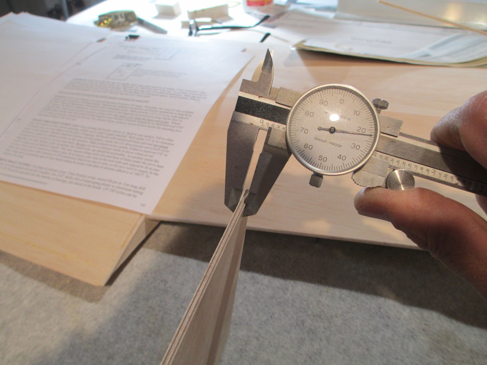
I'm using 1/8" 5 ply birch plywood which measures .122". I'll use the plywood as spacers between the top and bottom laminate giving me .001" clearance between the drive shaft and the inside of the pocket.
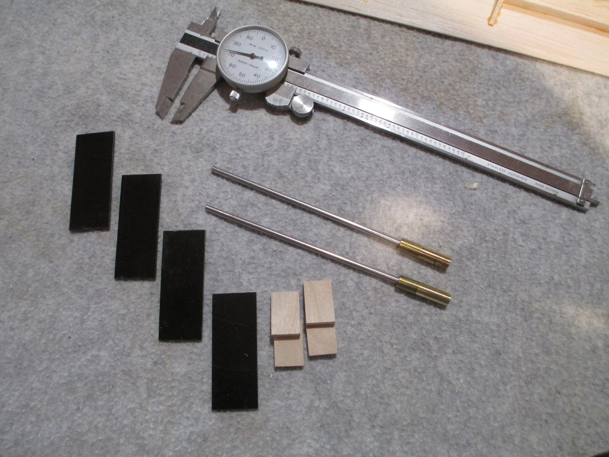
The plywood has been cut to size.
Before I mix the epoxy, note that I scuffed the surfaces of the plastic laminate that will contact the plywood. This will give better adhesion between the ply and laminate once the epoxy is spread.
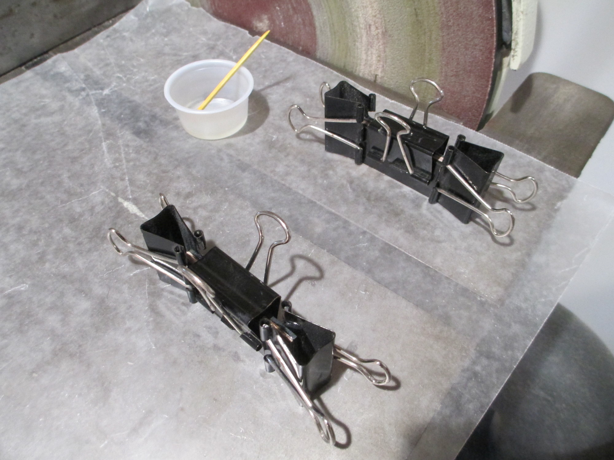
Epoxy was mixed and the pockets have been clamped. Time to wait for the epoxy to dry...
Trying to keep this plane as scale as I could, I wanted to have the external aileron linkages disappear. I researched how this could be accomplished and settled on the Rotary Drive System (RDS). This is by no means new technology, as this method of moving control surfaces has been around quite a while and has been used a lot by slope soaring enthusiasts. This is however something new for me, and if I don't get this to work...well let's not go down that road!
The process starts with four rough cut pieces of plastic laminate. Bob donated the laminate for this project. They will become the top and bottom of the RDS pocket.
Each of the four pieces were cut to their exact sizes (3/4" x 2").
The stainless steel drive shaft was measured using a dial caliper. These drive shafts were custom made just for this project...
Note the dimension on the caliper.121".
I'm using 1/8" 5 ply birch plywood which measures .122". I'll use the plywood as spacers between the top and bottom laminate giving me .001" clearance between the drive shaft and the inside of the pocket.
The plywood has been cut to size.
Before I mix the epoxy, note that I scuffed the surfaces of the plastic laminate that will contact the plywood. This will give better adhesion between the ply and laminate once the epoxy is spread.
Epoxy was mixed and the pockets have been clamped. Time to wait for the epoxy to dry...
Last edited by VincentJ; 10-13-2019 at 02:03 PM.
10-13-2019, 03:40 PM
#314
Thread Starter
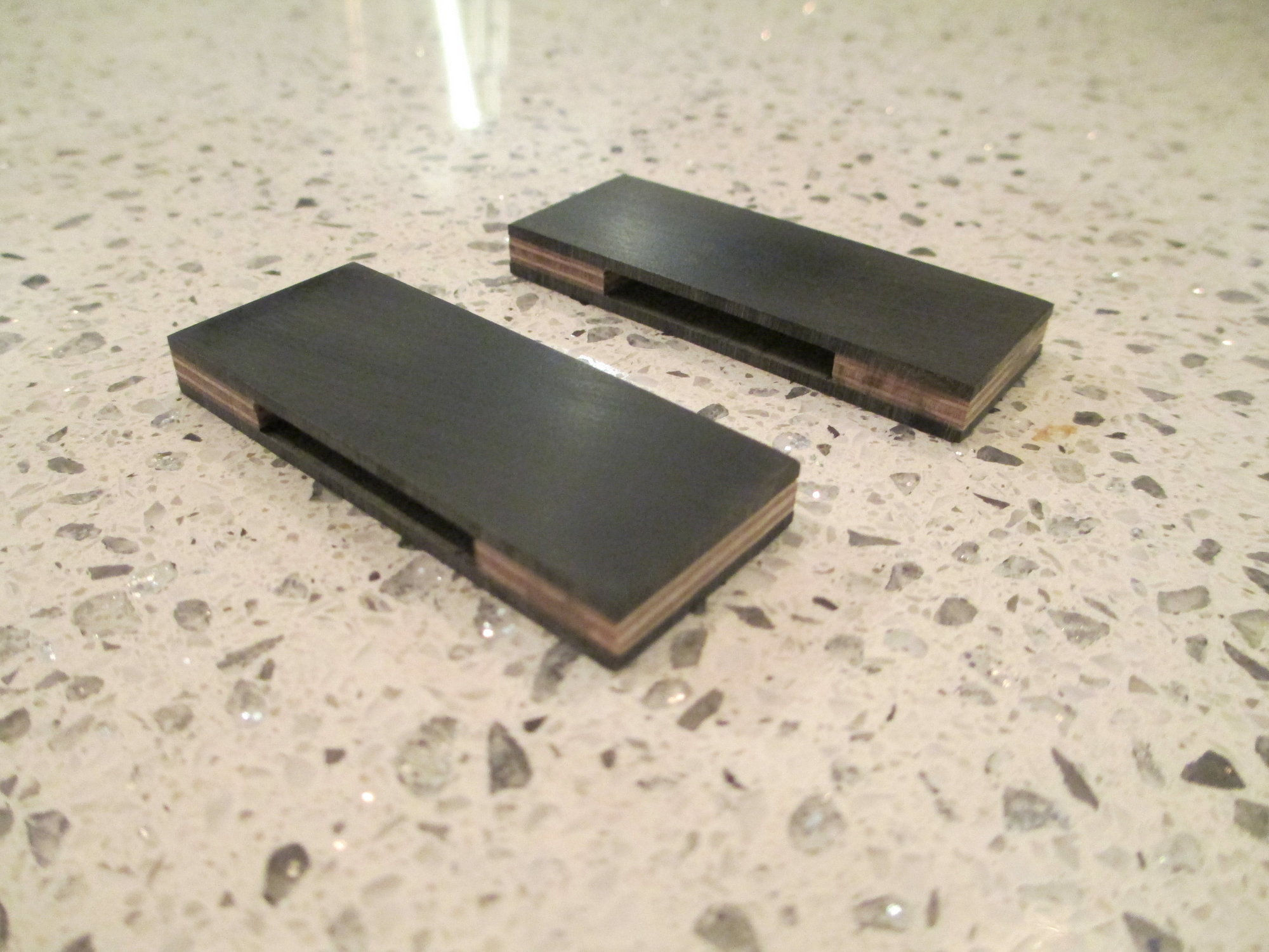
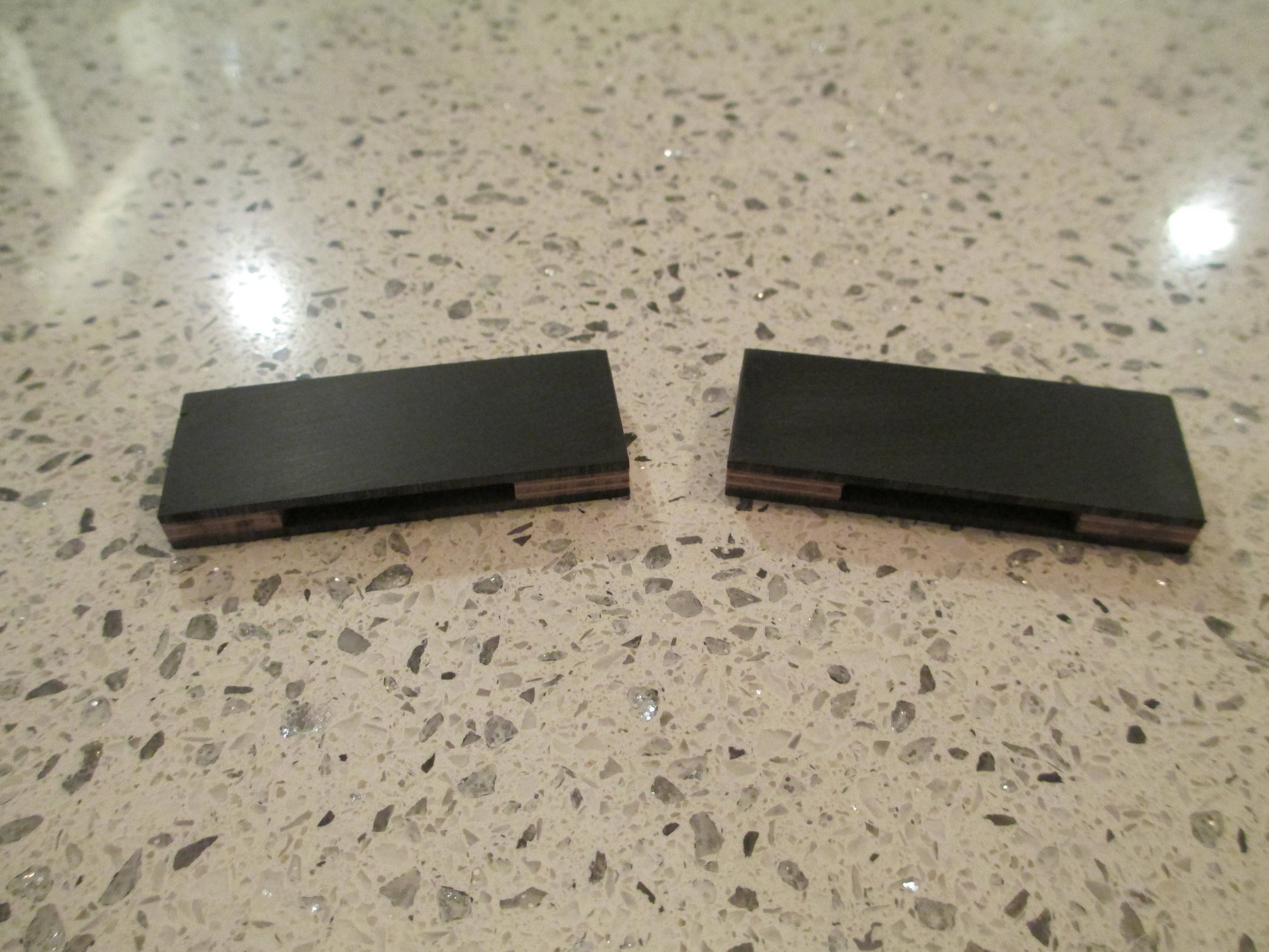
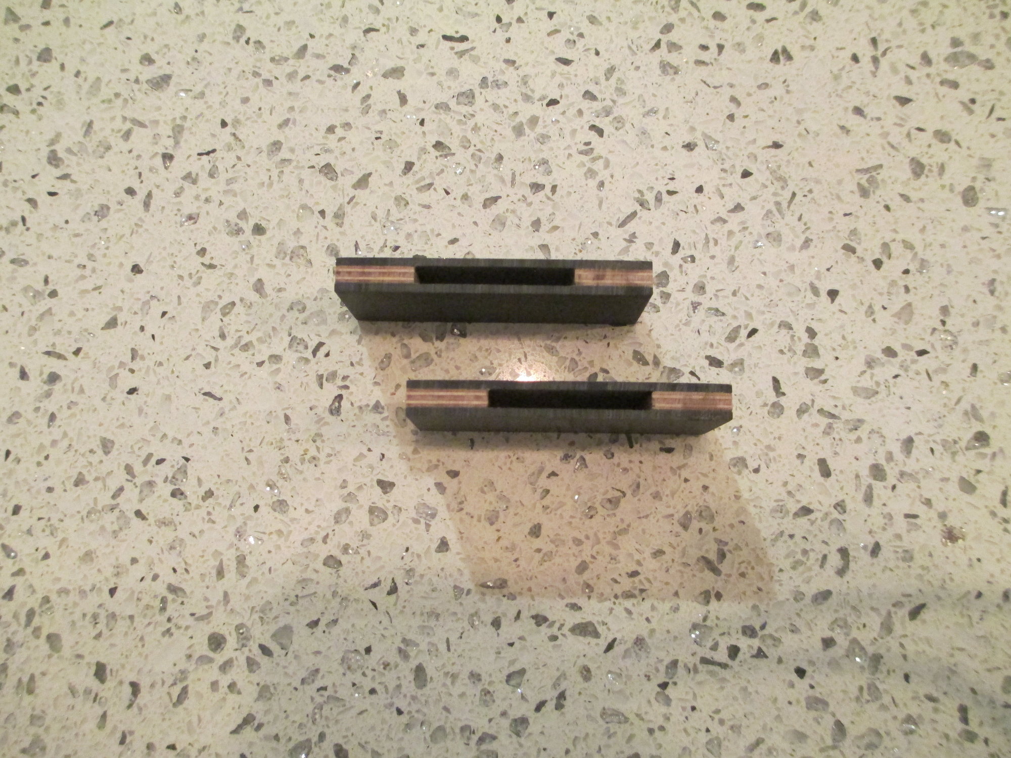
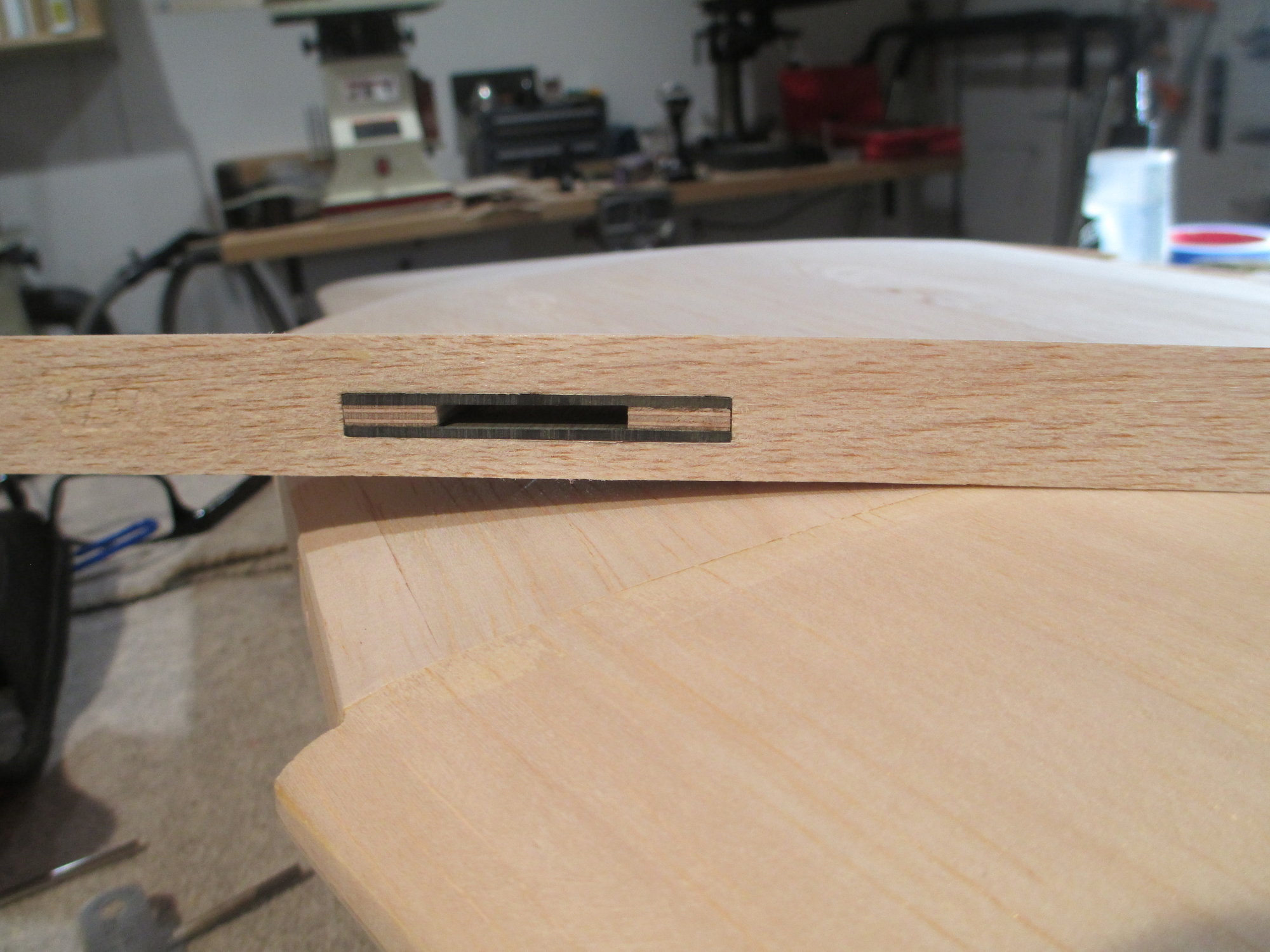
Completed pockets. One for the right aileron and one for the left. They may appear large in the photographs, but they are quite small measuring 3/4" x 2".
Last edited by VincentJ; 10-13-2019 at 11:33 PM.
10-14-2019, 03:25 AM
#316
Thread Starter
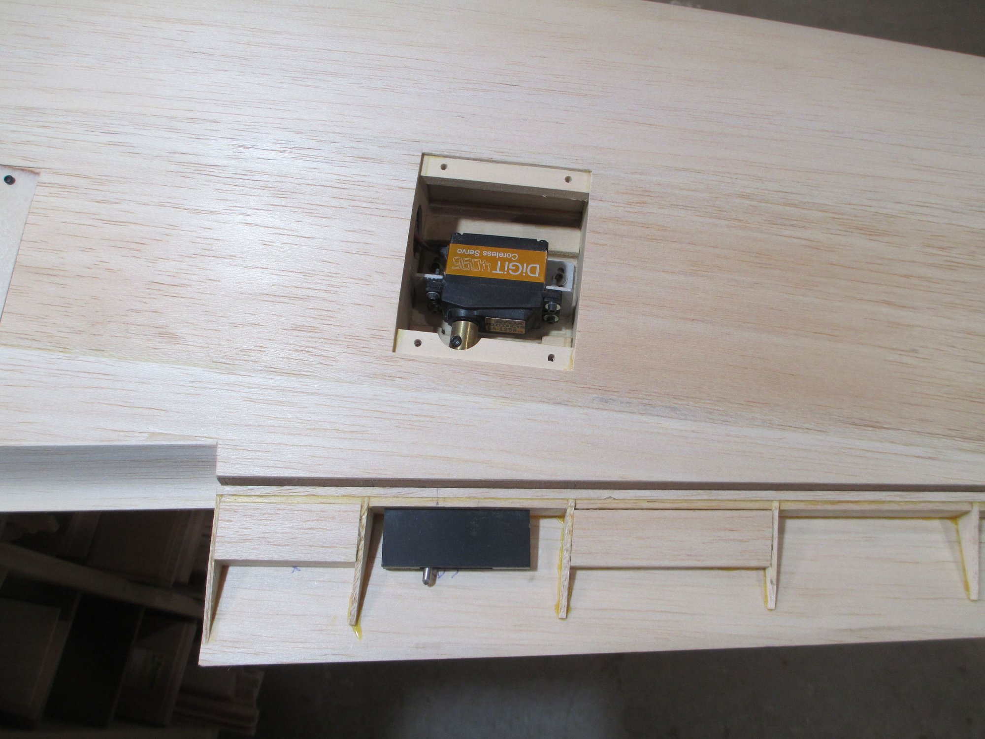
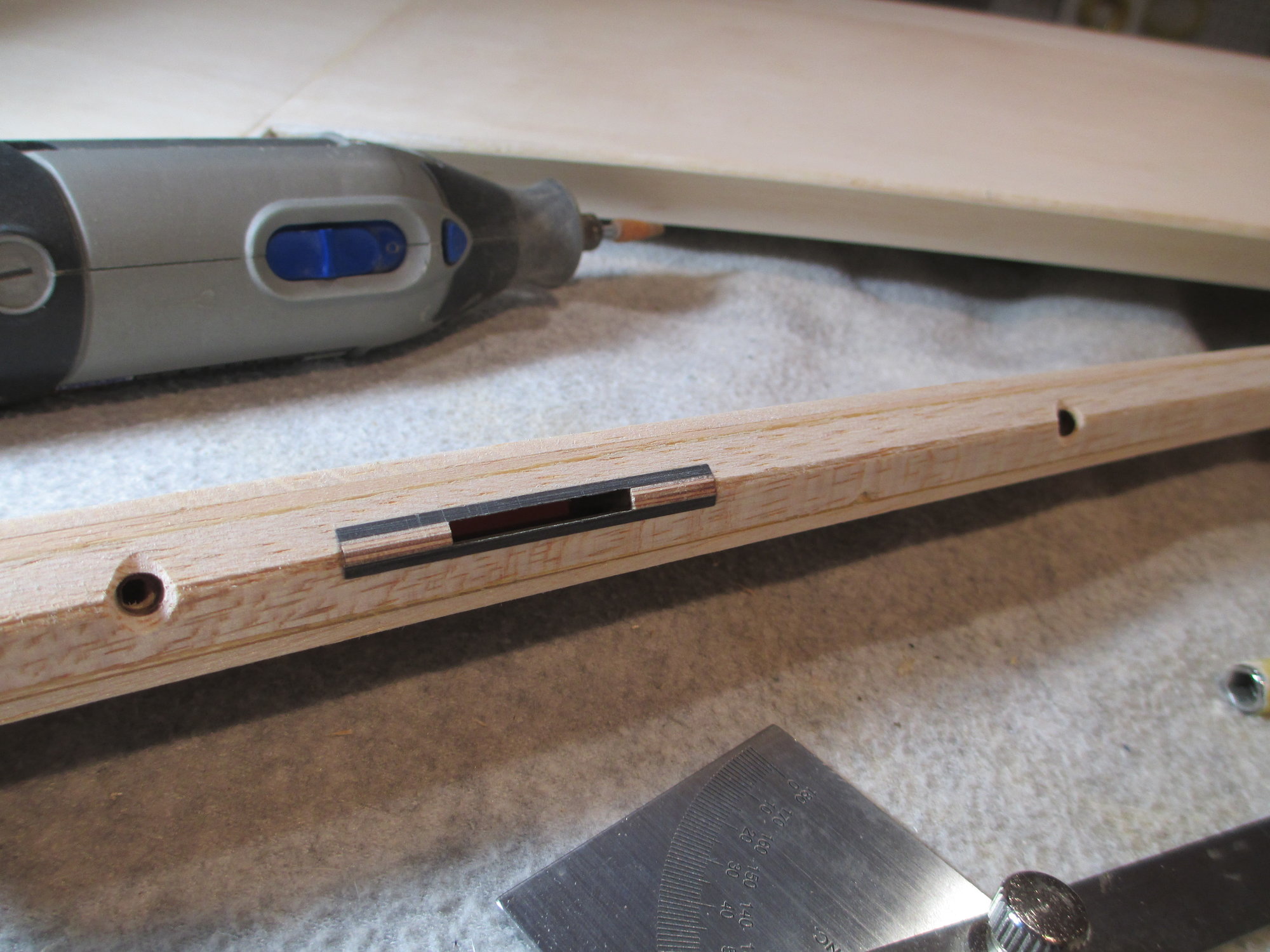
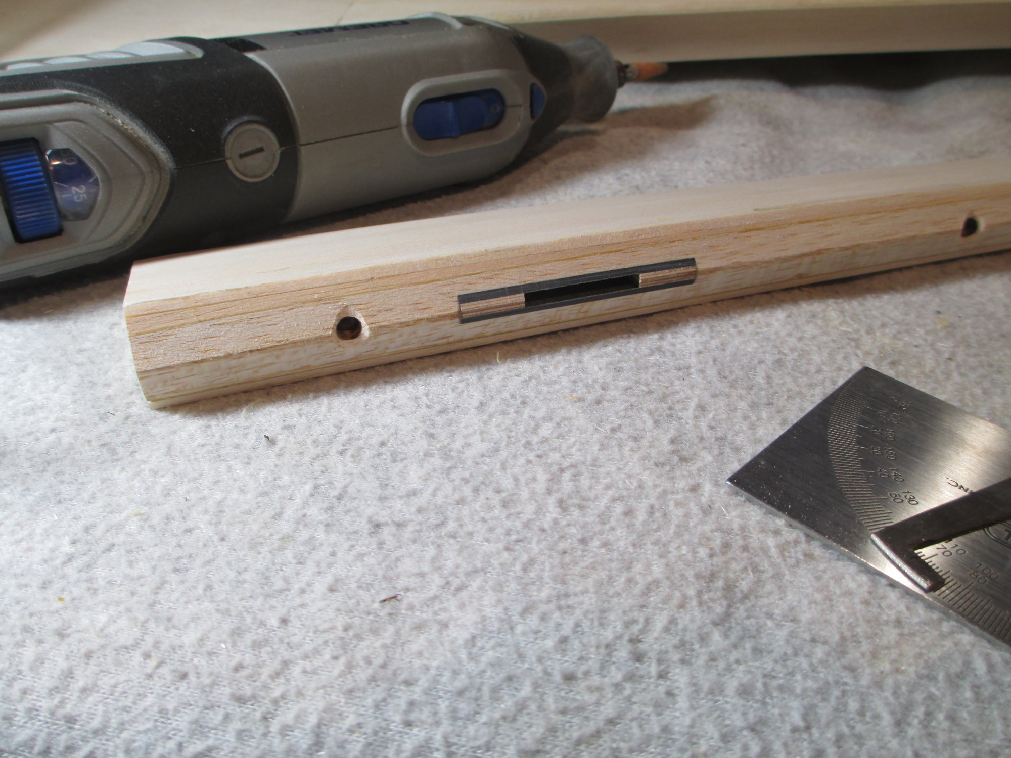
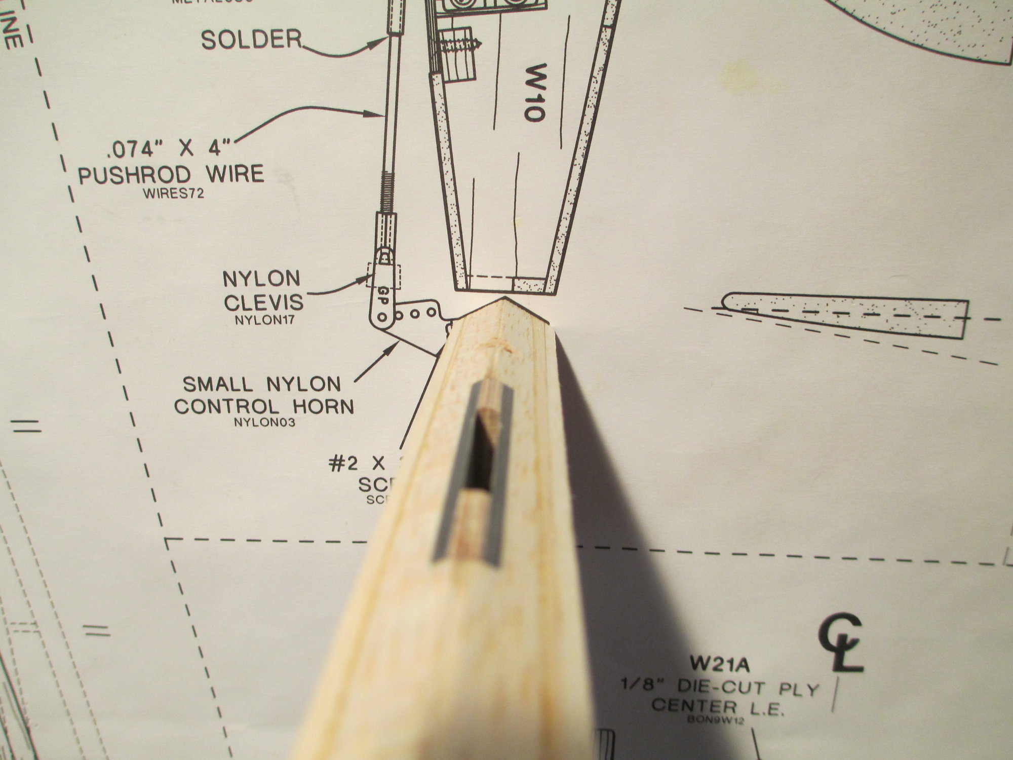
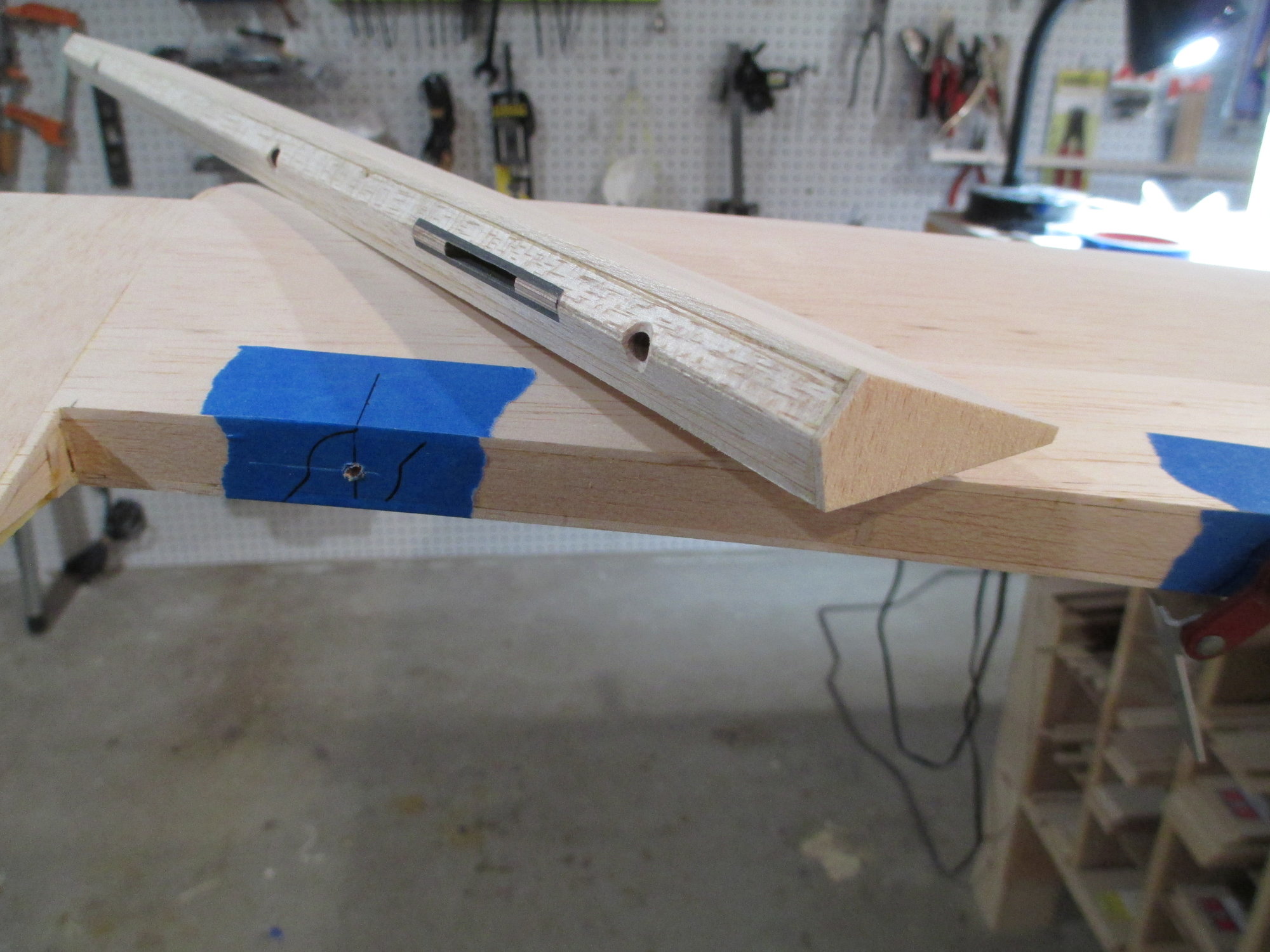
I positioned the pocket in the aileron bay by inserting the driveshaft through the aileron and pocket giving me perfect alignment. Note: The end of the drive shaft is not bent at this time.
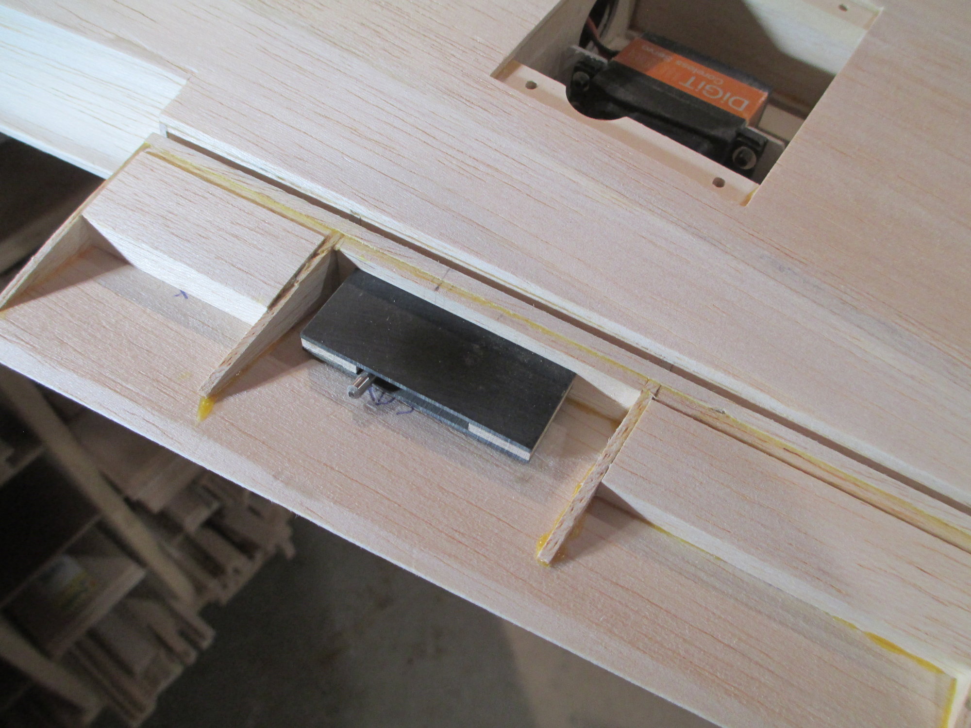
Using a pencil, I mark the pockets exact position in the bay.
The balsa within the scribed area was carefully removed so as to ensure the pocket will fit snugly.

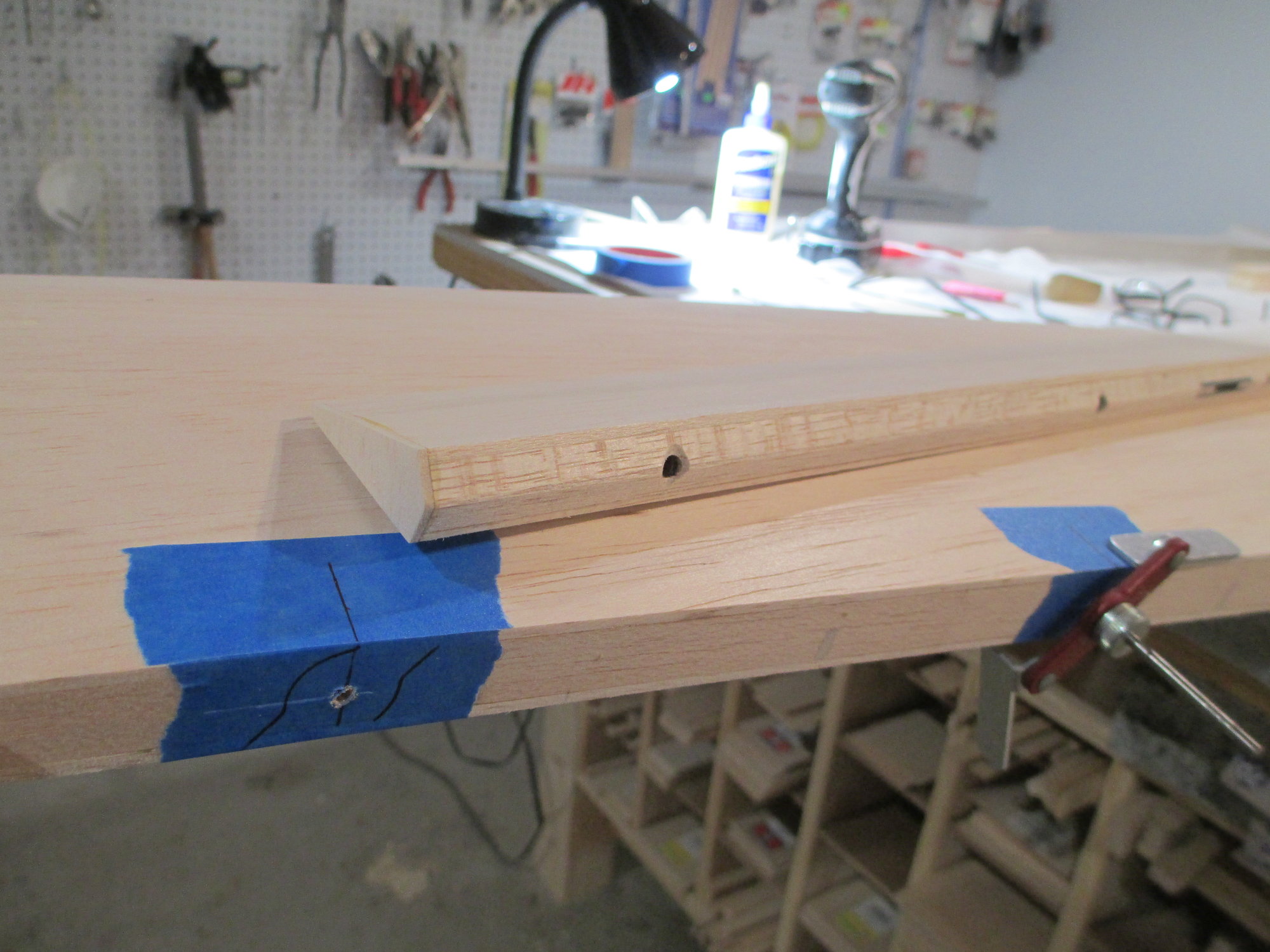
A test fit of the pocket.
The pocket is fully seated and flush against the aileron's leading edge. The LE of the aileron will be beveled later to allow for the control surface to deflect up and down.
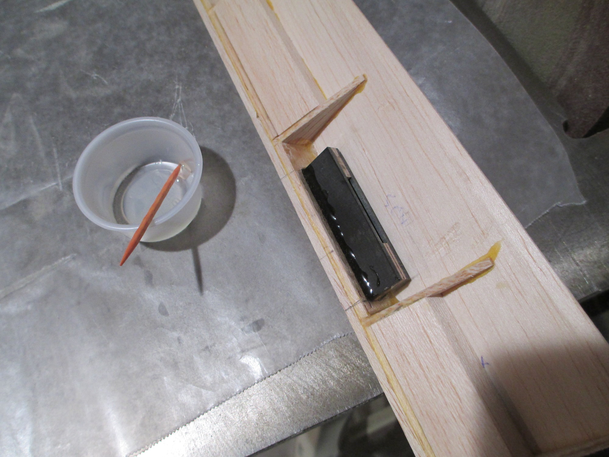
The pocket is permanently epoxied into position.
 10-14-2019, 11:57 AM
#319
Thread Starter
10-14-2019, 12:00 PM
#320
Thread Starter
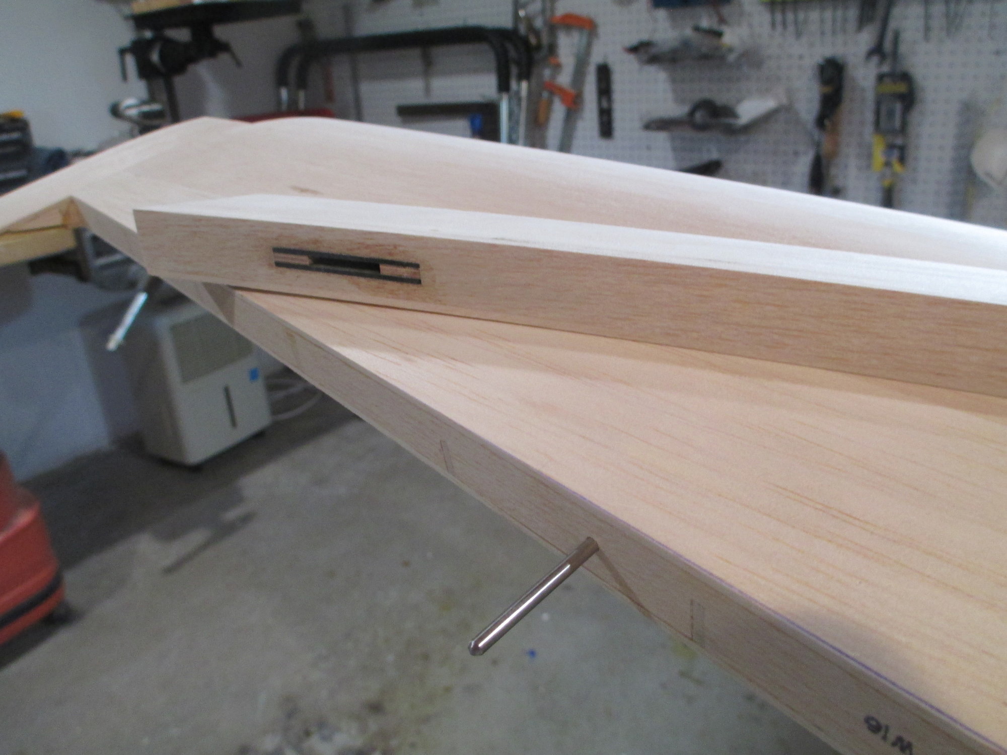
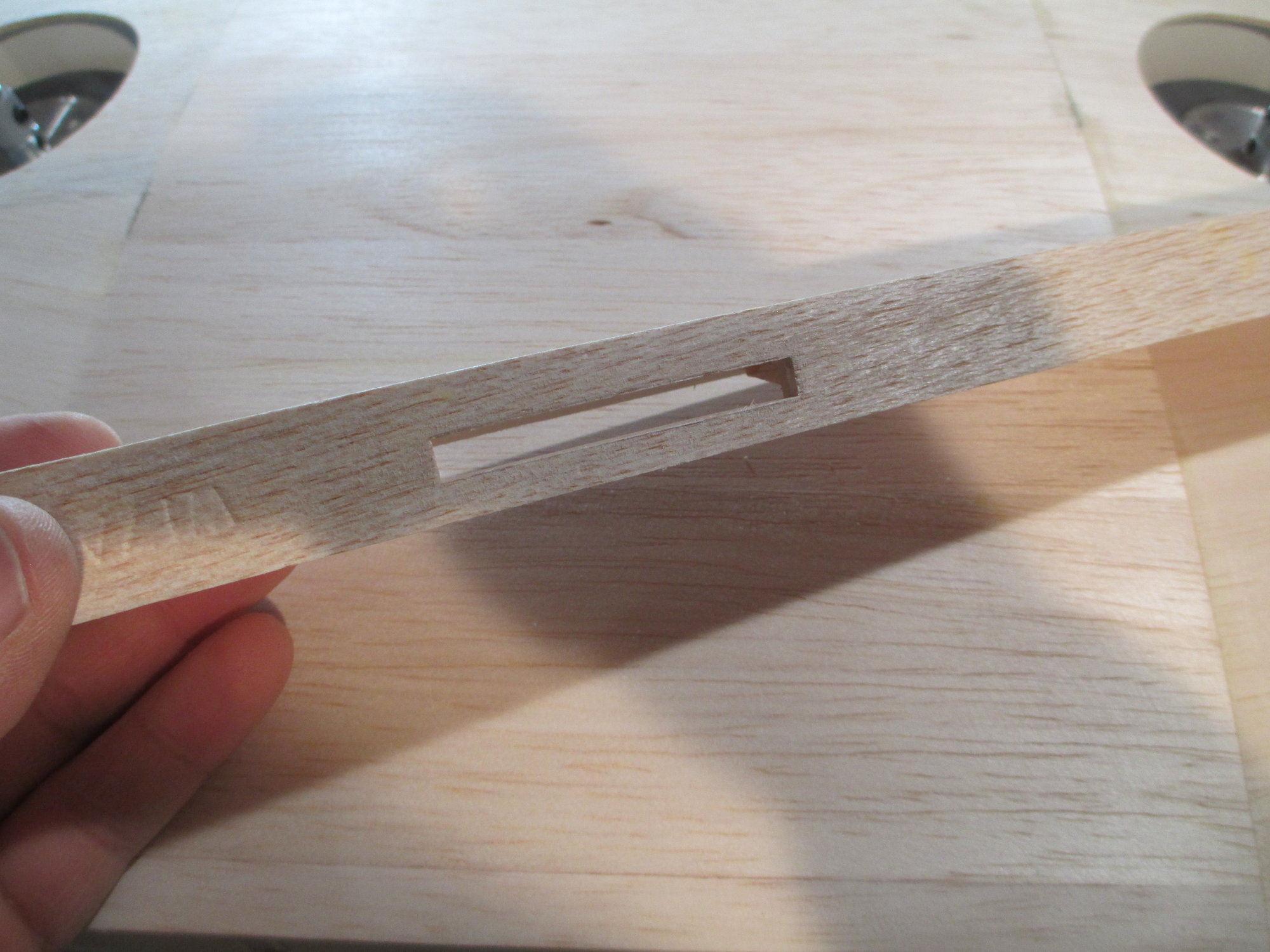
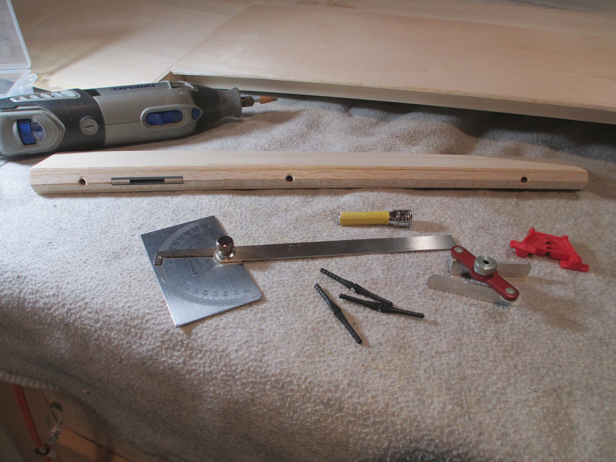
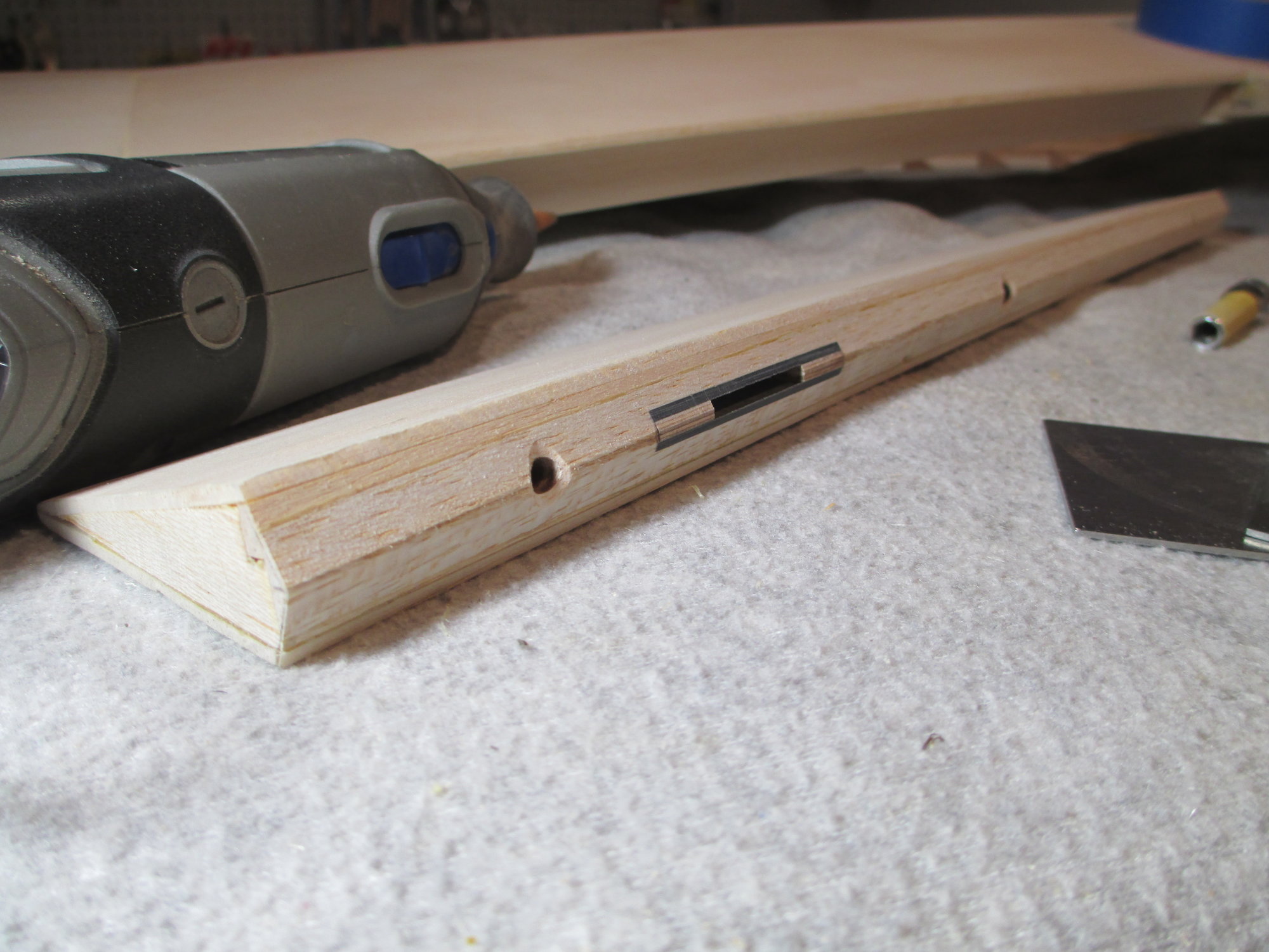
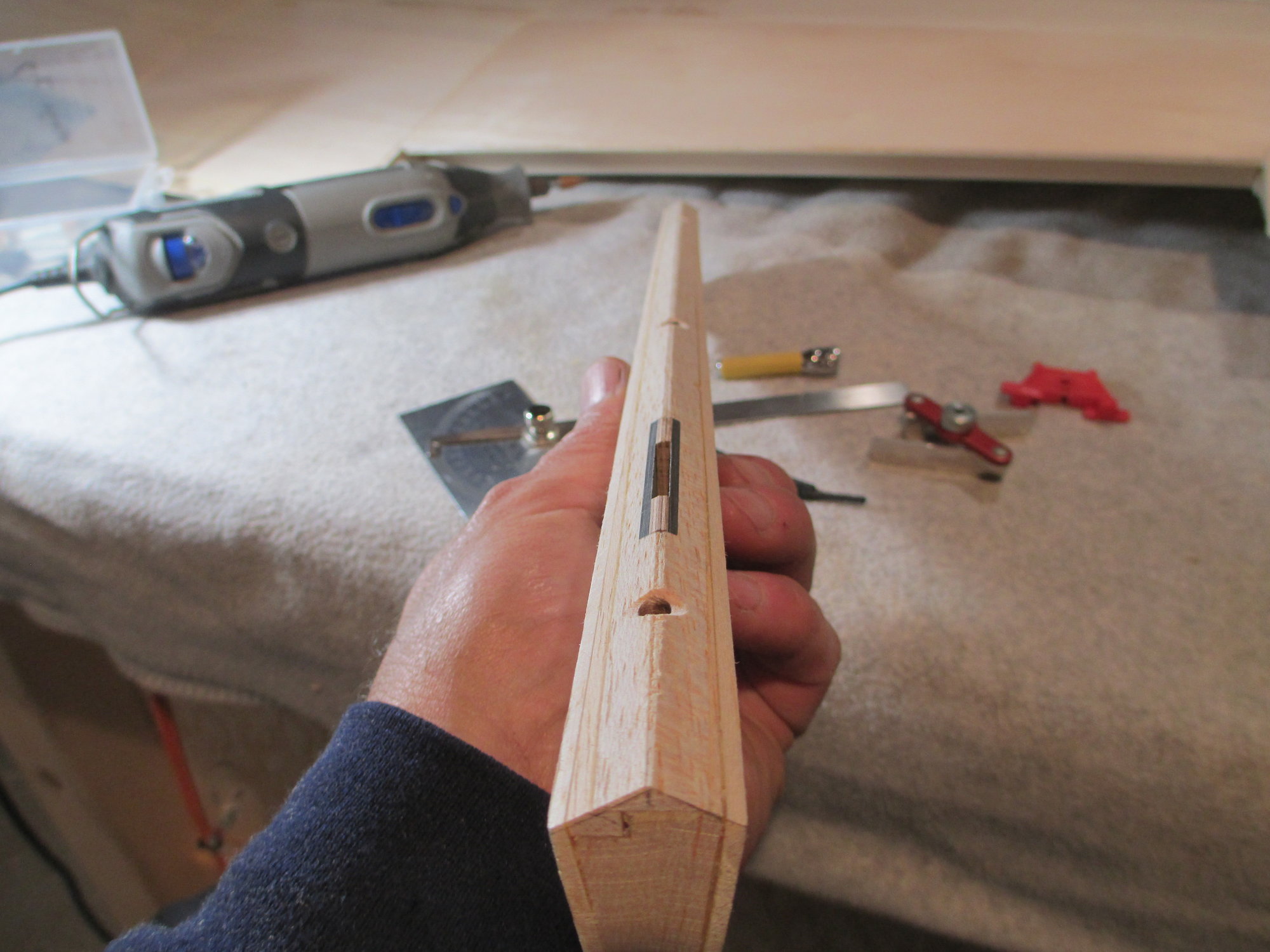
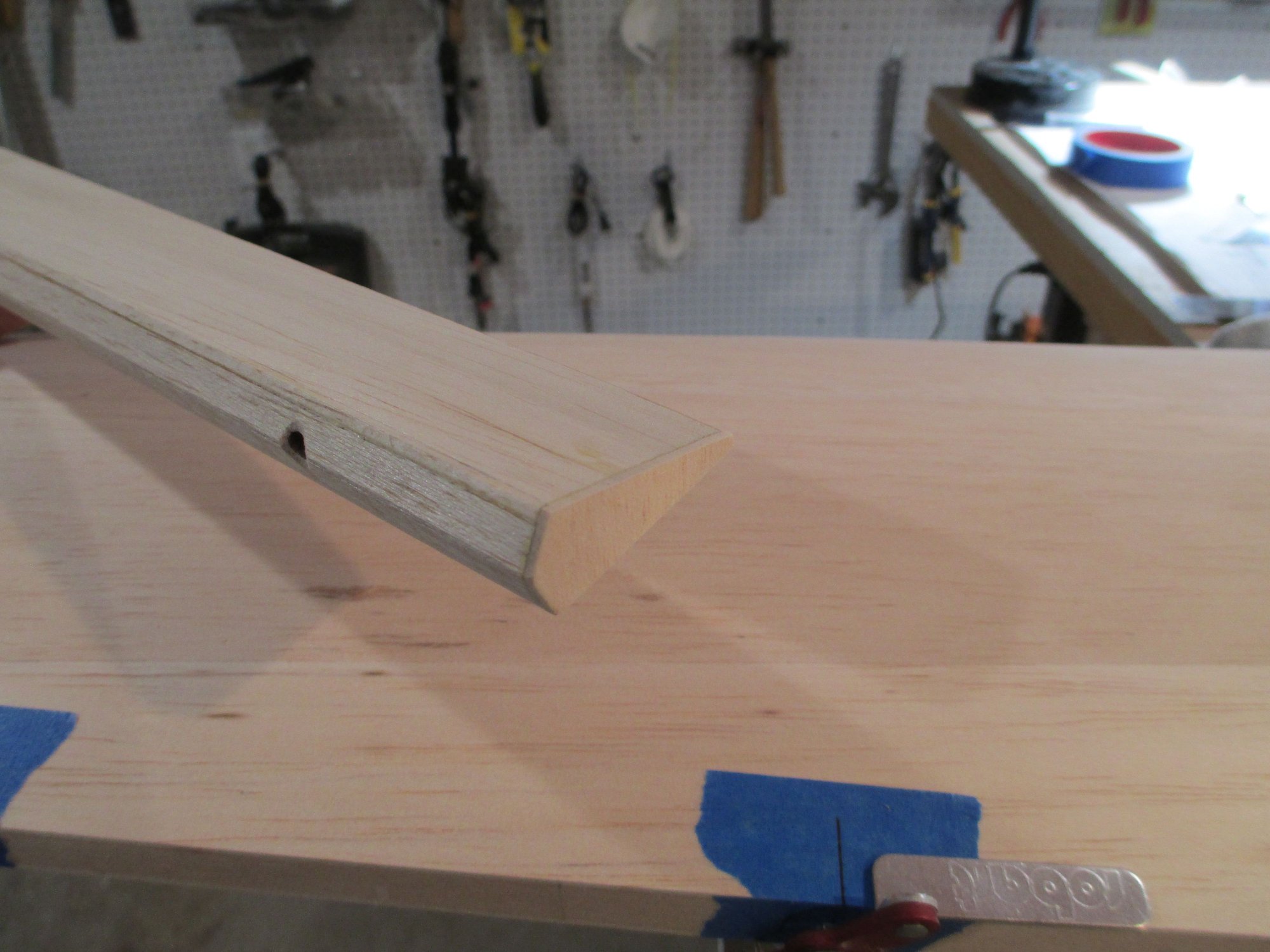
The finished pocket in the completed left aileron.
With the drive shaft in the "pocket", the alignment of the aileron on the wing is spot on.
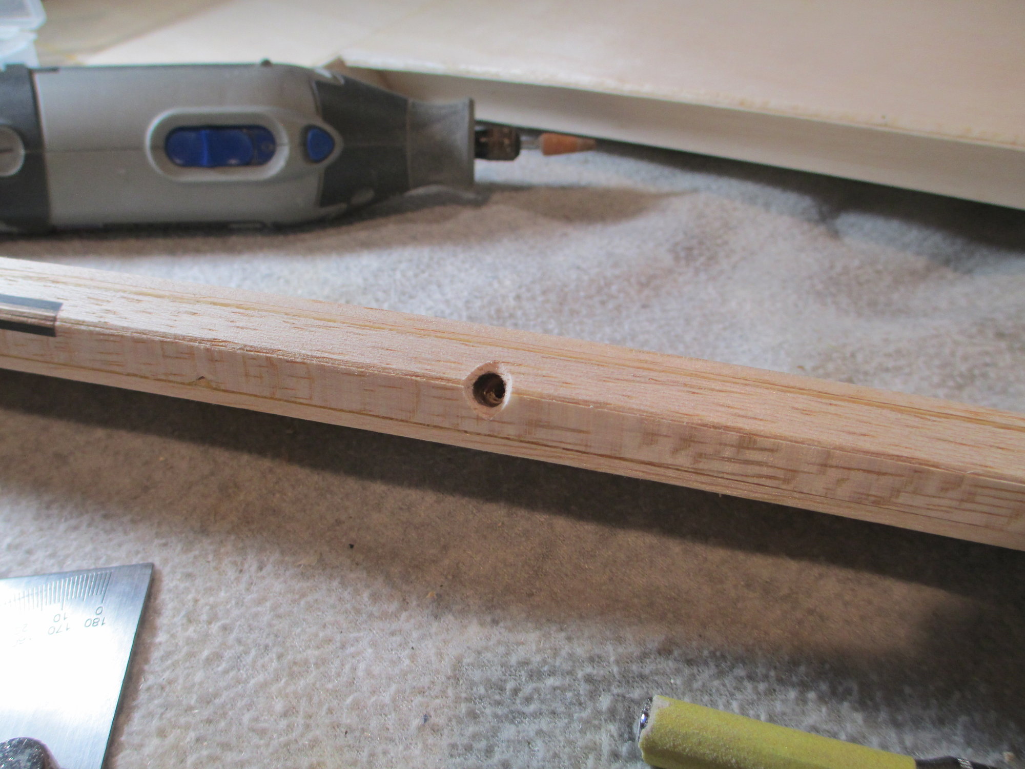
Getting ready to drill for hinge points.
Last edited by VincentJ; 10-15-2019 at 12:28 AM.
10-15-2019, 03:34 PM
#323
Thread Starter
I didn't explain what I did in the following photos as I've already previously covered how I install hinge points. All of the usual suspects were rounded up to get the job done. I will mention however, the angle on the aileron's leading edge was a bit of a challenge due to the aileron tapering with length. I hand sanded the angle using my assortment of sanding bars. All in all, I'm pleased with the results...
Last edited by VincentJ; 10-16-2019 at 03:20 AM.
10-17-2019, 12:41 AM
#324
Thread Starter
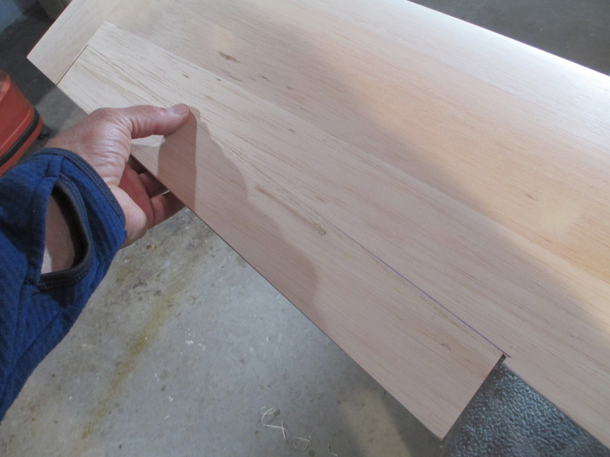
One detail that I like to include is to cap the ends of the ailerons/flaps. It does absolutely nothing in terms of adding strength, just more of a cosmetic thing. It does however allow me to fine tune the gap between the end and wing pocket by sanding to keep all of the gaps consistent. Just more of my OCD kicking in...
10-17-2019, 01:11 AM
#325
You might want to consider capping the wing cutout and surface edges with 1/64 ply.
I do it on most of my builds because it gives a super sharp edge that stands up to wear and tear over the years.
I do it on most of my builds because it gives a super sharp edge that stands up to wear and tear over the years.