


Top Flite 1/7 P-51 Build
 02-02-2016, 07:26 AM
#3176

I worked on locating the gear last night and this is what I ended up with. I lowered both the mounting rails 1/4 inch which allows room for the outer door to cover the entire retract without coming in contact with it. This will let me design a hinged outer door so when retracted everything will be covered. I have some fine tuning to do but conceptually I think I can make this work. In order for a hinged door to work I had to come up with a way to attach to the strut that would move along the length of the strut. I used two brass tubes, flattening one for the strap and some epoxy putty to attach the two together. As I said I love pictures so here are a few and if the pictures move, even better!
https://youtu.be/42Zp2nvGJQc


https://youtu.be/42Zp2nvGJQc
Last edited by BigTeeEldorado; 02-02-2016 at 07:28 AM.
 02-02-2016, 07:39 AM
#3177

Join Date: Aug 2013
Posts: 10
Likes: 0
Received 0 Likes
on
0 Posts
I did my aileron bays differently than the flaps. I ran my rails along the ribs. I'm reusing some aileron hatches from a H9 corsair I crashed last year as they were the perfect fit and angled so the push rod is nearly perpendicular to the aileron hinge line. Because the wing is slightly cambered, the hatch will sit below the 1/16th sheeting and I'll put balsa on the top of the hatch and contour it to the camber of the wing. I also used the rib die-cuts and made rib doublers glued to the outside of each rib of the aileron bay for added strength.

I have BARELY enough room for a standard servo!
As far as the gear, I spent all day fitting the left retract into the bay. I had to cut about .5 inch vs the planned .25 inch notches for the rails. Don't use thicker rails, it means you have to cut deeper notches into the ribs! If you look at the profile of the retract, the strut is centered on the top of the mounting rail. This is why the gear door is challenging for me and it will be left out. The best I could do is get the top of the tire nearly flush with the future wing sheeting. Dropping the 3.5 inch Robart tire into its bays eats into the W-4 rib to give clearance to the cylinder and bracket of the retract.
 02-02-2016, 08:01 AM
#3179
Join Date: Aug 2013
Posts: 10
Likes: 0
Received 0 Likes
on
0 Posts
It sounds like we dropped the gear to about the same depth into the ribs. I'll revisit the gear door option! Did you go with the 85 or 90 degree retracts? It seems maybe the 90 degree gear would've been a better option allowing the wheel to retract further into the bay...
02-02-2016, 08:20 AM
#3180
Pete, are those 3 1/2 or 3 1/4 wheels and where did you get them, they look like they might be the Robart scale wheels. I thought the 3 1/4 was the largest wheel the struts would take. I need to work on that end of the installation too so I need to get some. There is no doubt everything is a a tight fit. You did almost exactly what I did your just ahead of me with actually gluing it in. I didn't make the rails thicker I did make them wider and notched them into the ribs a little for a better fit. I am also looking at making some additional plywood doublers that would tie into the spar a little better. Right now the balsa rib is all that really holds the gear because the ply doubler isn't notched into the spar. It doesn't help that we have cut away most of 4 which leaves me a little concerned.
 Mine are 85 degree....I was kind of thinking that same thing
02-02-2016, 09:04 AM
#3181
Join Date: Aug 2013
Posts: 10
Likes: 0
Received 0 Likes
on
0 Posts
02-02-2016, 09:20 AM
#3182
Pete, FYI...I just got off the phone with Robart (unrelated issue) but I asked a few questions about our installation. Here is what I got....the 85 degrees is the relationship between the mounting rails and the locked down position of the strut. The locked up position is the same for either the 90 or the 85 with respect to the mounting rail. Common sense really but confirmed. So the 90 degree units would require the unit to be tipped to compensate for dihedral and get the wheel farther into the wing, it could not be done with additional travel. That is really the same as the 85 degree plus we have already cut about as much as we can from w4 and we would have to cut even more in order to change the mounting rail angle using the 90 degree. In looking at where I am right now with my cuts, I don't think I can tip a 90 degree enough to make it work so the 85 is still the right unit for me I think. If you choose to not do the doors it might work for you but the retract unit will definitely stick up above the surface of the bottom wing sheeting in order to get it tipped enough.
Just watched your video and that is exactly what I am going to try and do with mine. I have the 3/8 struts so I have to stay with a 3 1/4 wheel.......If yours is 3 1/2 should not make much difference.
Just watched your video and that is exactly what I am going to try and do with mine. I have the 3/8 struts so I have to stay with a 3 1/4 wheel.......If yours is 3 1/2 should not make much difference.
Last edited by BigTeeEldorado; 02-02-2016 at 09:29 AM.
02-02-2016, 02:27 PM
#3183
Join Date: Aug 2013
Posts: 10
Likes: 0
Received 0 Likes
on
0 Posts
I decided to go with the 662 struts and the 3 1/2 inch wheels. I figured the beefier struts and larger wheels might come in handy flying off a grass. After my epoxy cures on the other gear, I'll come back and reinforce the mounting rails. Your rails look nice and tight. there is a lot of slop with mine, which is why I have to do some reinforcing. The 85 degree gear I think are perfect for this wing, I'm glad I didn't go with the 90 degree set. Back to work!
02-02-2016, 05:25 PM
#3184
From what I can see the rc specialties turbo muffler will fit perfectly and exit at the bottom. I'm going to use two life batteries and if needed locate the receiver battery in the back. I'm also going to be using a beefed up version of the single aileron servo set up. I will be glassing and painting it as well. I'm running the e-flight retracts as well with 3.5 inch dave brown lite flight wheels. I'm hoping these tend to come out a little nose heavy so this engine will benefit me up there. When I get a chance I'll be sure to throw some pictures up here. Thanks for the advice!
02-04-2016, 08:22 AM
#3185

Join Date: Nov 2014
Posts: 46
Likes: 0
Received 0 Likes
on
0 Posts
Thanks, I had thought about going with a single 3200 life but I got worried about running one battery for both. What is an opto-coupler? I did purchase a spektrum 2200 life for the receiver and a 1450 life for the ignition so I'm hoping that works well. One thing I did have a question about it I'm getting ready to sheet the wings but is there a good technique to figure out where to cut the sheeting for the retracts once it's sheeted? The manual doesn't exactly tell you how to do it, I have some ideas but I'm not exactly confident with them.
02-04-2016, 09:06 AM
#3186
Thanks, I had thought about going with a single 3200 life but I got worried about running one battery for both. What is an opto-coupler? I did purchase a spektrum 2200 life for the receiver and a 1450 life for the ignition so I'm hoping that works well. One thing I did have a question about it I'm getting ready to sheet the wings but is there a good technique to figure out where to cut the sheeting for the retracts once it's sheeted? The manual doesn't exactly tell you how to do it, I have some ideas but I'm not exactly confident with them.
As for cutting the skin, what I am planning is a little more involved because I am going to do doors. But here is my thought. Before you sheet the bottom make a template with a thin piece of cardboard with the opening cut out that you can test by operating the gear. You can locate the correct positioning of the template later off the seam from the leading edge and sheeting. If you already sheeted maybe you could make one from the plans.
02-04-2016, 10:53 AM
#3187
http://www.badbradgraphics.com/image...ll_switch2.jpg
Its used to isolate the ignition from the RX, and have a means to disable the ignition from the transmitter. Its basically a fancy kill switch for a gas engine. Instead of using a mechanical switch that could cause interference from vibrations, it optically isolates the power between the ignition and the receiver, and when you flip a switch on the transmitter that is tied to the port it plugs into it breaks that optic connection, turning the ignition off.
02-04-2016, 12:32 PM
#3190
Interesting, should only be a link to the image on his site. http://www.badbradgraphics.com/photo_16.html
02-04-2016, 01:42 PM
#3191
Good. I bought a lot of stuff from him, he travels to the local swap meets and if you ever have an issue with any of the stuff he sells, he quickly takes care of it. Nice guy too.
02-05-2016, 09:16 AM
#3193
He is, and has some great graphics. They are a bit pricey, but high quality materials are used. He does have a limit on size though, he wont be able to do my Biper Bears for the Cub, they are too small for his cutter. I might have to use a decal printer instead.
He used to sell RX packs, but he got a bad batch of them, and refunded everyones money and stopped selling them.
He used to sell RX packs, but he got a bad batch of them, and refunded everyones money and stopped selling them.
02-05-2016, 10:52 AM
#3194

You can also try callie graphics http://www.callie-graphics.com/ She has lots of schemes and will do custom work very resonable. Best life batteries are here www.hangtimes.com Military grade
02-05-2016, 12:34 PM
#3195
My Feedback: (2)
I had a problem with my TF P-51. The first item that I started on was the stab and it warped like a potato chip. Did anyone else ever encounter a problem like this? Setup was very careful, not sloppy at all.
I admit to using yellow glue, to make sanding the LE and TE easier, but used it very sparingly.
Any thoughts??
Bob
I admit to using yellow glue, to make sanding the LE and TE easier, but used it very sparingly.
Any thoughts??
Bob
02-05-2016, 04:54 PM
#3196
Join Date: Aug 2013
Posts: 10
Likes: 0
Received 0 Likes
on
0 Posts
Bob, I built a Cub a few years back and wasn't careful about storing during the build. It warped badly. I wet it well, hung the warped half off the end of the table and hung a light weight from the TE corner to counter the warp. I checked it a couple days later and it was straight! Maybe the same technique could work for you...
Pete
Pete
02-05-2016, 05:42 PM
#3197
Join Date: Nov 2014
Posts: 46
Likes: 0
Received 0 Likes
on
0 Posts
when I did the horizontal stab my first one did get warped and I had to order parts to redo it. What I realized is I had the grain going horizontal but when you look at the pattern they want the grain going at the same angle as the front (leading edge) of the stab. Once I did that it was much better.
Thanks for the callie graphics. I think with this big gas O.S. four stroke impatient virgin? is fitting! Oh yeah I am building a p-51B by the way.
Thanks for the callie graphics. I think with this big gas O.S. four stroke impatient virgin? is fitting! Oh yeah I am building a p-51B by the way.
Last edited by DanIsGo; 02-05-2016 at 05:45 PM.
02-06-2016, 05:21 AM
#3198
My Feedback: (2)
Thanks for the replies... I found that my stab had warped right on the building board. It had been weighted down while the glue dried, But found that it had curled like a birds wing (as opposed to a twist) and this was what had mystified me. I didn't think that I had used a lot of yellow glue but perhaps the water in the glue was the primary cause of the warp.
I had decided to use the yellow glue on the areas that would need sanding and shaping later, like the LE. I didn't want to sand rock-hard CA'd balsa.
I'll take another look at the old stab again. I've already bought parts for a new one, except for the LE. The sheet with that part was EXPENSIVE, so I made my own. It's all waiting for me.
Bob
02-07-2016, 03:14 PM
#3199
Hey Pete.....have you gotten any farther along? I had to put the wing aside for a few days because I had to send back the retracts. One of them had a problem. Without the hardware I can't finish up a couple of things before sheeting or I just know I'll mess it up.
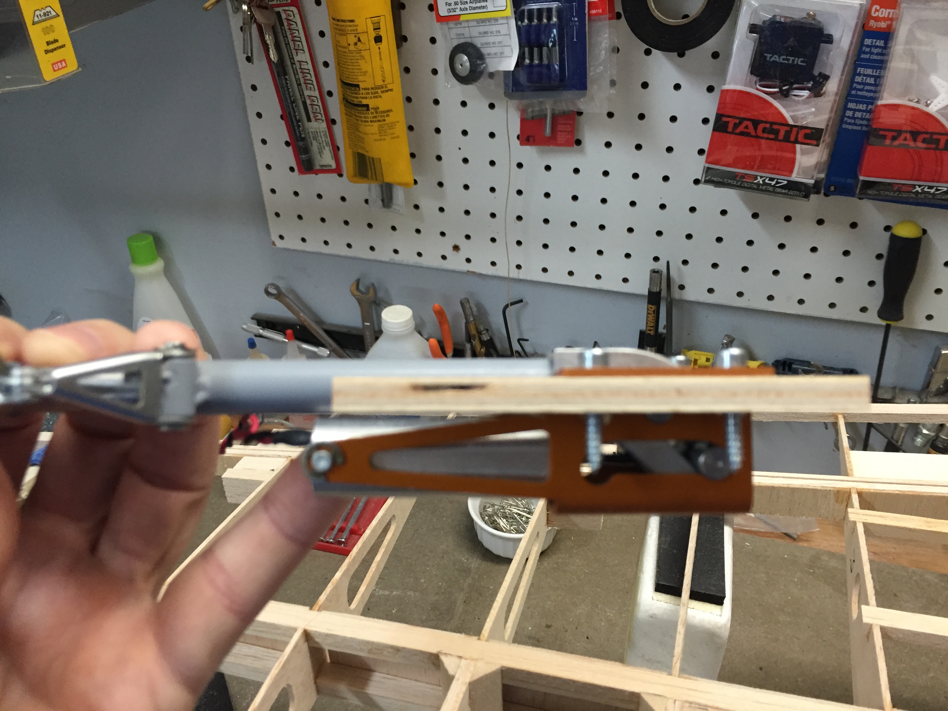
So I started on the fuse. Got most of it together on Saturday afternoon/evning but then had to slow down to focus on the tail wheel. I spent all day Sunday fitting the retractable tail wheel assembly. Most of the time was spent re-rigging the steering arms, but I think what I have will work. This is how it ended up.

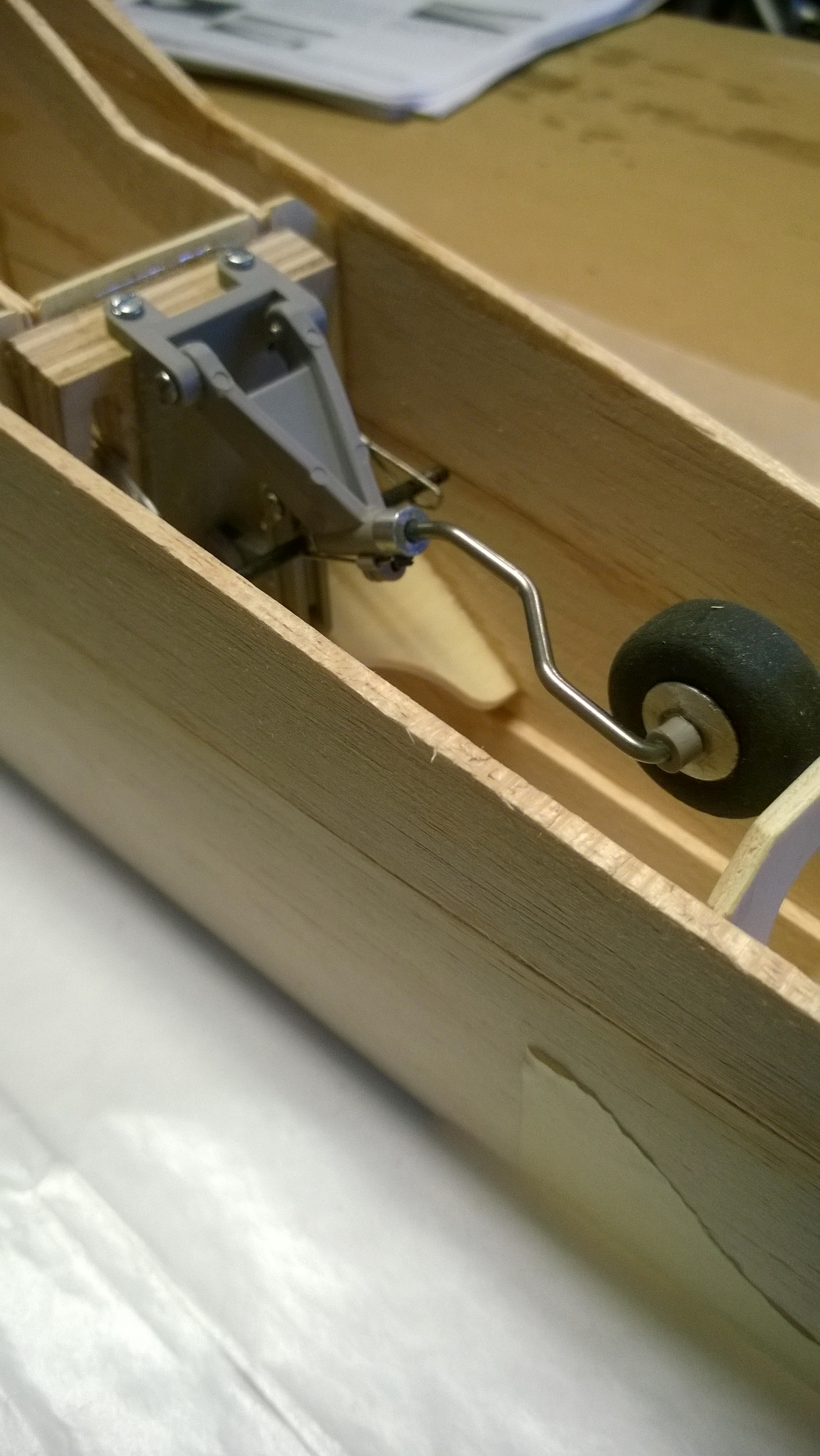
So I started on the fuse. Got most of it together on Saturday afternoon/evning but then had to slow down to focus on the tail wheel. I spent all day Sunday fitting the retractable tail wheel assembly. Most of the time was spent re-rigging the steering arms, but I think what I have will work. This is how it ended up.
02-07-2016, 05:26 PM
#3200
Hey Pete.....have you gotten any farther along? I had to put the wing aside for a few days because I had to send back the retracts. One of them had a problem. Without the hardware I can't finish up a couple of things before sheeting or I just know I'll mess it up.
So I started on the fuse. Got most of it together on Saturday afternoon/evning but then had to slow down to focus on the tail wheel. I spent all day Sunday fitting the retractable tail wheel assembly. Most of the time was spent re-rigging the steering arms, but I think what I have will work. This is how it ended up.
So I started on the fuse. Got most of it together on Saturday afternoon/evning but then had to slow down to focus on the tail wheel. I spent all day Sunday fitting the retractable tail wheel assembly. Most of the time was spent re-rigging the steering arms, but I think what I have will work. This is how it ended up.
I used the same tail wheel, took a while to get it working, and found that if I used a separate arm to connect to the tail wheel cables, and link it to the rudder servo, I was able to get it to work better than trying to tie it directly to the rudder servo.

