


In-Line Twin projects
 08-30-2013, 02:42 AM
#1
Senior Member
Thread Starter

Join Date: Aug 2013
Posts: 444
Likes: 0
Received 0 Likes
on
0 Posts
Following on from my introduction post: http://www.rcuniverse.com/forum/rc-a...ing-hello.html I'll put the progress on these boats here. The idea is to build in line twin airboats, two the same, one electric and one IC.
After some time spent fiddling with fuel arrangement I needed to try the setup out for real, so a quick build is needed to get the engines on the water.
So, with the thought of using a boogie board being dashed by no one in the family being able to tell me where ours have got to") yesterday I put this together:
yesterday I put this together:


This also helped with a new material I'm trying for modelling, PVC Foam board (i'll report fully on my thoughts on this material when I've done some more). I've gone too heavy for this test bed boat as it will have a future as a test bed for a petrol engine I've a hankering to have a go at. The material is recycling old sign boards with zero outlay, which appeals to me on a throwaway boat. Some sign vinyl roll ends gave a quick fuel proof finish.
Next I'll work on the engine and rudder mounts.
After some time spent fiddling with fuel arrangement I needed to try the setup out for real, so a quick build is needed to get the engines on the water.
So, with the thought of using a boogie board being dashed by no one in the family being able to tell me where ours have got to
yesterday I put this together:This also helped with a new material I'm trying for modelling, PVC Foam board (i'll report fully on my thoughts on this material when I've done some more). I've gone too heavy for this test bed boat as it will have a future as a test bed for a petrol engine I've a hankering to have a go at. The material is recycling old sign boards with zero outlay, which appeals to me on a throwaway boat. Some sign vinyl roll ends gave a quick fuel proof finish.
Next I'll work on the engine and rudder mounts.
Last edited by Jeremy_H; 08-31-2013 at 05:32 PM. Reason: link to OP inserted so people know what I'm heading for
 08-30-2013, 04:37 PM
#3
Senior Member
Thread Starter
Join Date: Aug 2013
Posts: 444
Likes: 0
Received 0 Likes
on
0 Posts
Thanks  .
.
Did most of the engine mount for the trial boat today, milled from a 5mm thick 'T' section Aluminium extrusion, with recesses on each side so the engines are on the same centreline. Glad I've made it as the final mount will be similar and a couple of things came to light. How to sort the throttle linkages (was hoping to mount the servo in the central cutout), and need to divert the exhaust on the aft engine (maybe custom exhausts for both, but certainly an elbow needed).


.Did most of the engine mount for the trial boat today, milled from a 5mm thick 'T' section Aluminium extrusion, with recesses on each side so the engines are on the same centreline. Glad I've made it as the final mount will be similar and a couple of things came to light. How to sort the throttle linkages (was hoping to mount the servo in the central cutout), and need to divert the exhaust on the aft engine (maybe custom exhausts for both, but certainly an elbow needed).
08-30-2013, 05:36 PM
#5


How thick is the mount where the engines actually bolt on? I used 1/16" aluminum L channel on my little SI3 with a Jett .35. The L channel cracked and broke within 6 tanks of fuel. Double the engines, double the vibrations.... Be careful and keep an eye on it if its less than 1/8" thick. And +1 in watching the fingers!
08-31-2013, 01:07 AM
#7
Senior Member
Thread Starter
Join Date: Aug 2013
Posts: 444
Likes: 0
Received 0 Likes
on
0 Posts
 ), even so, I've decided that tuning will be with one engine running only, and I'll extend the needle valves if it helps.
I have a couple of small Chinese machines, a modified Mini MIll and an 8x16 lathe. I've had to do some major work to sort their problems out and make them more usable, a belt drive conversion and digital readout setup for the mill, and a complete drive train replacement for the lathe in the form of an inverter and three phase motor. The mechanics on these machines is excellent value for money, the electrics and drives on both were rubbish:
I share the concerns over the mount's strength. A 1/16th mount is a little under 1.6mm thick, this one is 2.5mm under the engine. I've used 3mm before in plate form with a .40 OK, but the stresses on this one are on on one side, plus with two engine vibration is going to be complex with two sources, i.e. not just twice the source, but the two could cause all manner of weird stresses as vibrations fight each other. So, as this is a boat to check over such things I'll keep a close eye on it. But, I think I'm already comitted to installing webs, or gussets, to the underside of each engine, one on each at least, probably lightened 5mm aluminium so that the engine bolts fix them to the vertcal web, and through bolted to the horizontal one. An alternative is to start with thicker extrusions, this is what I have at the moment. One other factor is the servo, that's a hostile place to be situated.
Last edited by Jeremy_H; 08-31-2013 at 01:30 AM.
08-31-2013, 04:13 AM
#8
Senior Member
Join Date: Apr 2011
Location: Melbourne, AUSTRALIA
Posts: 274
Likes: 0
Received 0 Likes
on
0 Posts
I really want a setup like that, but just cant justify, nor afford it
I'd suggest a bell crank arrangement for your throttles.... put the servo somewhere safer
I'd suggest a bell crank arrangement for your throttles.... put the servo somewhere safer
08-31-2013, 06:19 AM
#9
Senior Member
Thread Starter
Join Date: Aug 2013
Posts: 444
Likes: 0
Received 0 Likes
on
0 Posts
I'll take that advice on the servo. I'll will see if there's a way of using bellcranks as you suggest.
I'll be running the mount later, I'll see if a vid can be done
Last edited by Jeremy_H; 08-31-2013 at 06:20 AM. Reason: just a thought...
 08-31-2013, 04:45 PM
#11
Senior Member
Thread Starter
Join Date: Aug 2013
Posts: 444
Likes: 0
Received 0 Likes
on
0 Posts
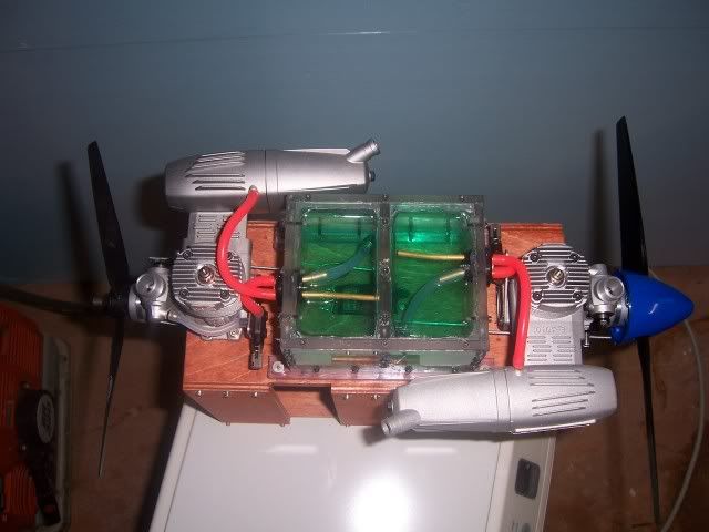
DIverted a little by pushing the test boat build forward, I really wanted RC control over those engines so needed to move the servo mounting along, so tasks grew  . For now I've rigged the servo as intended, just the linkages to put in, mounted the tanks in the position they will be on the target boat, and stole a sandwich box from the kitchen for the radio gear.
It's quite compact in the engine area, but will have to be smaller still for the final boat: The mount is 2mm Dural, it takes some effort to flex it by hand, only running will show if it's stiff enough. If not, some cross bracing underneath will sort it. A couple more fixing screws to the hull needed.

The exhaust direction issue has been resolved using a silicone elbow from an R/C car for now, I'll rotate the silencer end towards the centre more to protect the deck before use: The vertical aluminium cylinder you can see is my own make non return valve. This may need to be lower so that the head of fuel puts a bigger closing action on it, but tests first.

I like using R/C Car tanks on boats, far less fiddly to fill. These were borrowed from a Hyper7 and an XT2 (wish I could get small parts into my sheet bender):

So all being well I can run tomorrow after the throttle linkage challenge, then the rudders to think about. Balance point is 1/3rd from the transom at the moment.:

. For now I've rigged the servo as intended, just the linkages to put in, mounted the tanks in the position they will be on the target boat, and stole a sandwich box from the kitchen for the radio gear.It's quite compact in the engine area, but will have to be smaller still for the final boat: The mount is 2mm Dural, it takes some effort to flex it by hand, only running will show if it's stiff enough. If not, some cross bracing underneath will sort it. A couple more fixing screws to the hull needed.
The exhaust direction issue has been resolved using a silicone elbow from an R/C car for now, I'll rotate the silencer end towards the centre more to protect the deck before use: The vertical aluminium cylinder you can see is my own make non return valve. This may need to be lower so that the head of fuel puts a bigger closing action on it, but tests first.
I like using R/C Car tanks on boats, far less fiddly to fill. These were borrowed from a Hyper7 and an XT2 (wish I could get small parts into my sheet bender
):So all being well I can run tomorrow after the throttle linkage challenge, then the rudders to think about. Balance point is 1/3rd from the transom at the moment.:
Last edited by Jeremy_H; 08-31-2013 at 04:50 PM. Reason: typos
09-01-2013, 02:43 AM
#12
Member
Join Date: Aug 2013
Posts: 65
Likes: 0
Received 0 Likes
on
0 Posts
Hello Jeremy.
Iterestingly fixed drive. What is the purpose of the use of such power? ? ?
You have a well-equipped workshop. Nice lathe and milling machine.
These works perfect machine. What kind of companies are these machines? ? ?
Greeting from Poland
Marek&Wojtek
Iterestingly fixed drive. What is the purpose of the use of such power? ? ?
You have a well-equipped workshop. Nice lathe and milling machine.
These works perfect machine. What kind of companies are these machines? ? ?
Greeting from Poland
Marek&Wojtek
09-01-2013, 08:50 AM
#13
Senior Member
Thread Starter
Join Date: Aug 2013
Posts: 444
Likes: 0
Received 0 Likes
on
0 Posts
Marek, the purpose is really just for fun, something different .
The lathe and milling machine are Chinese manufacture, they are sold around the world with different names, in the UK 'Clarke', 'Axminster' and the people I bought mine from 'Amadeal'. In the US they are mostly have the name of 'Grizzly'. They are simple machines, but with some work they can be made much better.
.The lathe and milling machine are Chinese manufacture, they are sold around the world with different names, in the UK 'Clarke', 'Axminster' and the people I bought mine from 'Amadeal'. In the US they are mostly have the name of 'Grizzly'. They are simple machines, but with some work they can be made much better.
09-01-2013, 02:29 PM
#14
Senior Member
Thread Starter
Join Date: Aug 2013
Posts: 444
Likes: 0
Received 0 Likes
on
0 Posts
http://www.youtube.com/watch?v=SOeirMMLXYw&feature=youtu.be
Lot's resulting from this! Haha!
List:
Mount needs a little bracing. Not the engine mount itself, the pylon or riser is moving a little on the aft end.
Fuel tanks need to be a little higher
Both fuel filters letting air in
Prop balance to be re-checked on the aft engine
Throttle linkage is a joke
Lot's resulting from this! Haha!
List:
Mount needs a little bracing. Not the engine mount itself, the pylon or riser is moving a little on the aft end.
Fuel tanks need to be a little higher
Both fuel filters letting air in
Prop balance to be re-checked on the aft engine
Throttle linkage is a joke
Last edited by Jeremy_H; 09-01-2013 at 02:32 PM.
09-01-2013, 04:24 PM
#15
Senior Member
Thread Starter
Join Date: Aug 2013
Posts: 444
Likes: 0
Received 0 Likes
on
0 Posts
Just a little diversion....
I've found some dogeared prints of two of my previous boats, These are scans and they may help to show what the target boats will look like as they are a development from these.
This is the first of this style during build, the one I showed previously with the tiger stripe paint:

And this was a subsequent one. This is actually a pattern or 'plug' for a GRP moulding, one was popped out of the moulds which worked succesfully, but sadly the moulds are not accessible any more, c'est la vie!

I've found some dogeared prints of two of my previous boats, These are scans and they may help to show what the target boats will look like as they are a development from these.
This is the first of this style during build, the one I showed previously with the tiger stripe paint:
And this was a subsequent one. This is actually a pattern or 'plug' for a GRP moulding, one was popped out of the moulds which worked succesfully, but sadly the moulds are not accessible any more, c'est la vie!
Last edited by Jeremy_H; 09-02-2013 at 02:45 PM. Reason: typos
09-03-2013, 03:41 AM
#17

Join Date: Feb 2004
Location: Lexington,
NC
Posts: 919
Likes: 0
Received 0 Likes
on
0 Posts
Great build.... made me think of the inline twin I built back in 2005. Engine mounting and throttle linkage was perfect but the COG was off. Scraped project after first water test.
http://www.youtube.com/watch?v=8lAxlQANbXI
http://www.youtube.com/watch?v=8lAxlQANbXI
 09-03-2013, 09:26 AM
#18
Senior Member
Thread Starter
Join Date: Aug 2013
Posts: 444
Likes: 0
Received 0 Likes
on
0 Posts
Ooh! Very interesting to see! Love that sound
I'd love to have an idea of where your CoG was. So much of yours is different to my current ideas, but mine is based on a predecessor so I'm sort of using that experience to design the twin.
A reminder of the original, and the new concept final design for mine:


Key points:
The final hull is not a flatty, it's my own variation where there is much lower lift on the bow because the wetted volume decreases moving forward, so it rested bow down. I had to add a mass of lead as ballast to the rear of the boat, I don't know the weight but I can tell you it was a 1" cube of lead, and it was sat over the very stern of the boat, quite substantial. Correct me if I'm wrong, but looking at yours it was sitting stern down too much? My engines are sitting much further forward, and I'm betting on the rear engine slightly counterbalanced by more volume forward on the hull will balance. QED. If your issue was not fore and aft then this particular perception of mine falls to pieces lol!
Turning to vertical balance is where I have to disagree with your install being perfect. Prop clearance on mine is to be a minimum, in reality below deck level as the deck is recessed. Just enough clearance to be safe, say 10mm. Engines are side mounted, this puts the silencers below crankshsaft height making a huge difference alone, but add the cylinder/head shift to the side and the CoG drops substantially.
My fuel tanks where never going to be up with the engines, the yellow boat above had its tank in the cowling behind the motor, and with this design hull I'd have a complete shift in handling as the weight reduced during running. It went from flattish turns on a full tank to a touch of spin-out oversteer on a near empty one, because the boat's centre of drag shifted forward as the tank emptied, hence lever advantage meant less slip and more dig and turn, not acceptable changes (bear in mind we are talking water rudder here). This is another reason why my tanks are to be much lower, and as close to the desired CoG as I can get them. The closer they are to the desired Cog the less impact fuel use will have on that CoG's actual position. This has to be coupled with hydrodynamic issues as pure CoG changes alone may be pertinent to an aeroplane, but not to a boat, because the weight of the boat changes the submerged volume changes. Hence, potentially, the operation of the boat will shift in ways other than sluggishness, it may steer completely differently as the centre of drag the steering has to pivot around can move as the boat rises. With two engines, the weight of double the fuel is not a factor which can be largely ignored with many regular boats. So these variances to yours, engine attitude, height and tank position/height, mean my CoG is going to be very much lower, I wonder if yours was detectably top heavy in turns? I get the impression the boat would heel a lot.
My test boat is yet to get wet, I'll see how it sits in water this evening.
Whatever, it's great to see another one, sorry to hear it didn't work out, I hope those two lovely engines of yours are in happier homes
I'd love to have an idea of where your CoG was. So much of yours is different to my current ideas, but mine is based on a predecessor so I'm sort of using that experience to design the twin.
A reminder of the original, and the new concept final design for mine:
Key points:
The final hull is not a flatty, it's my own variation where there is much lower lift on the bow because the wetted volume decreases moving forward, so it rested bow down. I had to add a mass of lead as ballast to the rear of the boat, I don't know the weight but I can tell you it was a 1" cube of lead, and it was sat over the very stern of the boat, quite substantial. Correct me if I'm wrong, but looking at yours it was sitting stern down too much? My engines are sitting much further forward, and I'm betting on the rear engine slightly counterbalanced by more volume forward on the hull will balance. QED
. If your issue was not fore and aft then this particular perception of mine falls to pieces lol!Turning to vertical balance is where I have to disagree with your install being perfect. Prop clearance on mine is to be a minimum, in reality below deck level as the deck is recessed. Just enough clearance to be safe, say 10mm. Engines are side mounted, this puts the silencers below crankshsaft height making a huge difference alone, but add the cylinder/head shift to the side and the CoG drops substantially.
My fuel tanks where never going to be up with the engines, the yellow boat above had its tank in the cowling behind the motor, and with this design hull I'd have a complete shift in handling as the weight reduced during running. It went from flattish turns on a full tank to a touch of spin-out oversteer on a near empty one, because the boat's centre of drag shifted forward as the tank emptied, hence lever advantage meant less slip and more dig and turn, not acceptable changes (bear in mind we are talking water rudder here). This is another reason why my tanks are to be much lower, and as close to the desired CoG as I can get them. The closer they are to the desired Cog the less impact fuel use will have on that CoG's actual position. This has to be coupled with hydrodynamic issues as pure CoG changes alone may be pertinent to an aeroplane, but not to a boat, because the weight of the boat changes the submerged volume changes. Hence, potentially, the operation of the boat will shift in ways other than sluggishness, it may steer completely differently as the centre of drag the steering has to pivot around can move as the boat rises. With two engines, the weight of double the fuel is not a factor which can be largely ignored with many regular boats. So these variances to yours, engine attitude, height and tank position/height, mean my CoG is going to be very much lower, I wonder if yours was detectably top heavy in turns? I get the impression the boat would heel a lot.
My test boat is yet to get wet, I'll see how it sits in water this evening.
Whatever, it's great to see another one, sorry to hear it didn't work out, I hope those two lovely engines of yours are in happier homes
Last edited by Jeremy_H; 09-09-2013 at 11:25 AM. Reason: typos
09-04-2013, 03:17 PM
#19
Senior Member
Thread Starter
Join Date: Aug 2013
Posts: 444
Likes: 0
Received 0 Likes
on
0 Posts
Now working on the air rudders. Early days, and I may stick a basic water rudder on in in the interim so I can use it this weekend, as I've never made an airboat with air rudders before and I've a lot to learn. But a start has been made:

Now, here's a thing. I've often made parts out of a simple cold layup of Carbon Fibre, Would this be a suitable material to use for the air rudders on the final boats? In my head stiff and light is just what's needed. This is an old moulding of a powerboat screen I did some years ago so show what the surface would look like:

Now, here's a thing. I've often made parts out of a simple cold layup of Carbon Fibre, Would this be a suitable material to use for the air rudders on the final boats? In my head stiff and light is just what's needed. This is an old moulding of a powerboat screen I did some years ago so show what the surface would look like:
09-05-2013, 02:06 PM
#20
Senior Member
Thread Starter
Join Date: Aug 2013
Posts: 444
Likes: 0
Received 0 Likes
on
0 Posts
Made up the rudder bearings, and some rudders with material I have, I'm thinking they should be bigger judging by other poeple's, but I've no idea how effective these would be.
What do you guys think?


Now I can do a float test, bathtime!
What do you guys think?
Now I can do a float test, bathtime!
09-06-2013, 05:35 PM
#22
Senior Member
Thread Starter
Join Date: Aug 2013
Posts: 444
Likes: 0
Received 0 Likes
on
0 Posts
Ups and downs today.
In effect, it's ready to run. Bar the pusher prop, which is a can of worms again because my order has been cancelled due to faulty stock . Back on the phone again tomorrow.
Finalised the rudder linkages and radio installation today. As predicted the rudder control rod path was too much for a single servo, so I put two in. The final boats will have a much straighter path for this link.


In effect, it's ready to run. Bar the pusher prop, which is a can of worms again because my order has been cancelled due to faulty stock
. Back on the phone again tomorrow.Finalised the rudder linkages and radio installation today. As predicted the rudder control rod path was too much for a single servo, so I put two in. The final boats will have a much straighter path for this link.
09-08-2013, 01:57 PM
#23
Senior Member
Thread Starter
Join Date: Aug 2013
Posts: 444
Likes: 0
Received 0 Likes
on
0 Posts
The pond session started badly as my radio gear went pear shaped in a big way, chattering servos and rudder lock over to start with, then channel swapping would you believe!! I don't know, but it went in the bin when I got home. Prior to that at the pond a freindly club colleague lent me his receiver and transmitter so we could continue with the tests, good man! :-)
In short, this lumpy boat couldn't get over the hump on to the plane on the one engine, it was on the edge of it downwind but ploughed somewhat the other way. It'll be interesting to see just how much difference the second engine will make.
Original rudders were respectable, but the next size up fayred better, I'll hold off on final judgements when I've got more thrust to deflect. I could get a comforable turning circle, but without being in a skimming mode it's a load of freeboard to turn in the water.
The fuel setup allowed me to empty a tank on the final run, but I didn't raise the tank height before trials as I said I would, so I'll get into that as I'm haviing to run rich to keep the draw, and that was flooding the glow plug on sharp throttle offs.