


Homemade Tandem Axle 'Crawler Hauler' Trailer Build
 05-09-2015, 01:25 PM
#1

Thread Starter

Join Date: Jul 2012
Location: Grand Haven, MI
Posts: 2,984
Likes: 0
Received 0 Likes
on
0 Posts
Hi Guys!
It all started a little over a year ago around the middle of February 2014. I started with literally, two pieces of aluminum angle each cut in half to form four sides of an imagined trailer. I then added one side of the main cross-brace to support the dovetail.


The black anodized 1/2" x 3/4" x 1/16" angle is extra from dad's workplace. I got the 1/2" x 1/2" x 1/16" aluminum angle from Menards, along with some 1/2" x 3/8" x 1/16" aluminum channel. While I was there I picked up a handy-panel for the trailer's deck.

In order to make the dovetail ramp, I had to bend the side rails. So I measured out the angle and cut a triangle in the side of the side rails, bent the rails down to the correct degree, added the other side of the main cross-brace, and bent the cross-braces to a tighter than 90* angle. I bolted the cross-braces together with 4-40 machine screws and locknuts. This formed the support for the ramp and really stiffed it up.


Next was building the tongue. I cut a piece of the channel I specified above and cut a slot in the front side of the trailer for the channel to fall in. I also added another cross-brace to support the tongue farther down the trailer, tying it in better and making it strong. After many prototypes, the tongue's side braces became existent, and tied the tongue to the front of the trailer a second time. For the photos, most of the hardware is mock up.


With the tongue in place, I decided that I wanted a suspension system. Most of the other RC trailers I saw on the web either didn't have suspension or were a sliding leaf setup. I think I made a thread here on RCU a couple months back about tandem suspension systems for a trailer. So unlike what I had seen, I opted for the double-eye leafs to try and get some legit articulation, while supporting the weight of a 6lb SCX10. I used Tamiya Hi-lift leafs A, B, D, and E. I couldn't find leaf C available anywhere, so I replaced it with leaf E in the stack.
It all started a little over a year ago around the middle of February 2014. I started with literally, two pieces of aluminum angle each cut in half to form four sides of an imagined trailer. I then added one side of the main cross-brace to support the dovetail.
The black anodized 1/2" x 3/4" x 1/16" angle is extra from dad's workplace. I got the 1/2" x 1/2" x 1/16" aluminum angle from Menards, along with some 1/2" x 3/8" x 1/16" aluminum channel. While I was there I picked up a handy-panel for the trailer's deck.
In order to make the dovetail ramp, I had to bend the side rails. So I measured out the angle and cut a triangle in the side of the side rails, bent the rails down to the correct degree, added the other side of the main cross-brace, and bent the cross-braces to a tighter than 90* angle. I bolted the cross-braces together with 4-40 machine screws and locknuts. This formed the support for the ramp and really stiffed it up.
Next was building the tongue. I cut a piece of the channel I specified above and cut a slot in the front side of the trailer for the channel to fall in. I also added another cross-brace to support the tongue farther down the trailer, tying it in better and making it strong. After many prototypes, the tongue's side braces became existent, and tied the tongue to the front of the trailer a second time. For the photos, most of the hardware is mock up.
With the tongue in place, I decided that I wanted a suspension system. Most of the other RC trailers I saw on the web either didn't have suspension or were a sliding leaf setup. I think I made a thread here on RCU a couple months back about tandem suspension systems for a trailer. So unlike what I had seen, I opted for the double-eye leafs to try and get some legit articulation, while supporting the weight of a 6lb SCX10. I used Tamiya Hi-lift leafs A, B, D, and E. I couldn't find leaf C available anywhere, so I replaced it with leaf E in the stack.
Last edited by DieHarder; 05-11-2015 at 10:00 AM.
 05-09-2015, 02:02 PM
#2
Thread Starter
Join Date: Jul 2012
Location: Grand Haven, MI
Posts: 2,984
Likes: 0
Received 0 Likes
on
0 Posts
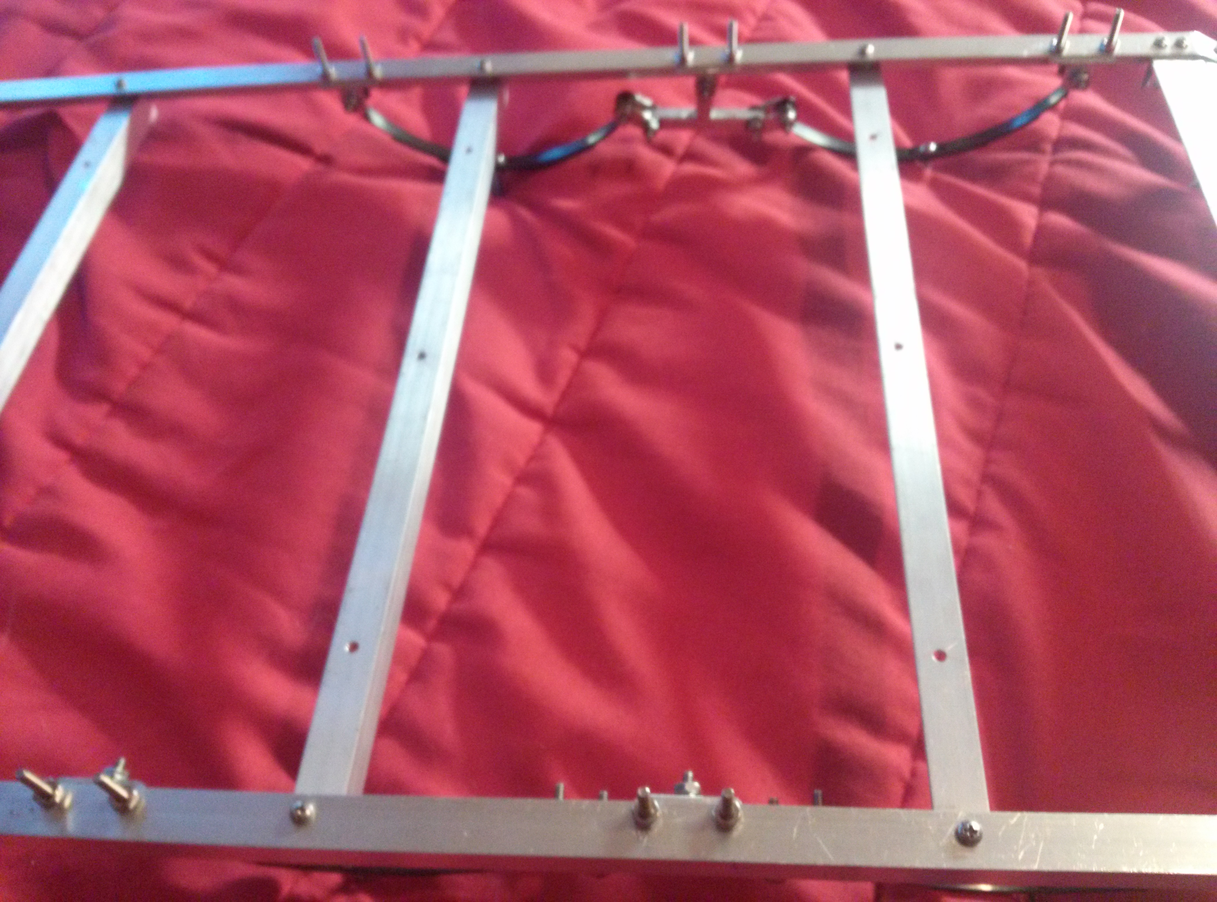
To achieve true tandem axle suspension, I needed an equalizer. And that is something I couldn't find available as well. So it was up to me to make one. Using a scrap piece of 1" x 1/4" aluminum bar about 8" long, I cut out some prototype equalizers. The design was changed each prototype and after the 4th one, I had a winner. Made another one to match and bingo! After measuring and cutting out shackles to tie the leafs to the equalizer and mounts (which took about 20 prototypes), I came up with 8 decent shackle plates. To make the suspension really scale, I needed leaf eye spacers. I searched around and couldn't find any purchasable. I actually found the right size tubing to make the spacers inside a pen. I cut the spacers off at the right length and began making leaf mounts out of the aluminum channel. Here it is all put together:


I proceeded to mount the suspension in the best place possible to achieve equal weight distribution between the leafs. I also added multiple cross-braces to strengthen the middle of the trailer deck and stiffen the frame.

With that, I installed some mock up random hardware to hold everything in place and did a photo shoot of my progress. From scratch, this is the point that I was at for building as of July 15, 2014.


I proceeded to mount the suspension in the best place possible to achieve equal weight distribution between the leafs. I also added multiple cross-braces to strengthen the middle of the trailer deck and stiffen the frame.
With that, I installed some mock up random hardware to hold everything in place and did a photo shoot of my progress. From scratch, this is the point that I was at for building as of July 15, 2014.
Last edited by DieHarder; 05-10-2015 at 05:26 AM.
05-09-2015, 05:04 PM
#3
Thread Starter
Join Date: Jul 2012
Location: Grand Haven, MI
Posts: 2,984
Likes: 0
Received 0 Likes
on
0 Posts
Next was the wood. The handy-panel had been an eyesore in my room, banging against my closet doors every time I went to get a shirt. Something had to change...
I measured the deck twice and with the help of dad, cut it once with an ancient but accurate radial arm saw. I decided that because of the overlapping metal and the changed deck mounting surfaces, the best bet would be to router the front and back of the deck and make the metal to wood transition of the deck smooth and level. This would leave the side rails 1/16" higher than the wood deck, which I liked.
Something else I had to have was LED lighting. I figured on 19 LEDs on the trailer, but ended up installing 13 for simplicity in where the wire would have to run. LED lighting was totally new to me. I've NEVER soldered to, installed, or even ordered LED lights. After lots of research, I found a guy on eBay who sold me (30) 5mm 6v LED lights (10 red [flat tip], 10 yellow [flat tip], and 10 white [regular]). They came with a resister already installed and the wires stripped and tinned, ready to solder. There wasn't much of a side rail left to put LEDs in after the 1/10" of wood subtracted from the 7/16" inside the angle, so the LED holes just barely made it on. I looked at the metal (chrome) LED holders, but they were too big to fit on the side rail. I didn't like it either how it was impossible to install the plastic holder on the LED that goes in the metal part, since the LED already had a resister solder on. So I bought some simple black plastic ones (which turned out GREAT!). At this point, I replaced all the mock up hardware with 4-40s of the correct lengths, washers where need be, and locknuts on everything.
Last edited by DieHarder; 05-10-2015 at 05:30 AM.
05-09-2015, 05:49 PM
#4
Thread Starter
Join Date: Jul 2012
Location: Grand Haven, MI
Posts: 2,984
Likes: 0
Received 0 Likes
on
0 Posts
And then the mail came...


I used Duratrax Evader ST front axle stubs, Duratrax bearings, Duratrax EXT2 rims, and Pro-Line 2.2 All-Terrain Badlands with stock foams. While Everything was starting to come together, the G6 started to get excited...


All the LEDs soldered in great! I had no trouble and I believe I did in fact improve my soldering skills. I used a 20AWG main wire to hook in to the LEDs and then ran it out through the tongue into a JST connector to connect to the truck.
On to the axles. I had to think about the exact design for quite a long time before finally executing it. I also took awhile to get my hands on some 1/2" x 1/2" solid aluminum bar to form them from. So basically I cut two lengths of the bar each 14.375" long. I setup the drill press and drilled a hole in each end of each axle 3/4" deep and 0.246" dia., which is press-fit for the 0.25" Duratrax axle stubs. I drilled a hole through the axle near the end, passing through the press-fit hole. Since the axle stub already had an existing hole, I press-fitted the stubs into the ends of the axles, lining up the holes in the stub with the cross holes in the axle, and put a 4-40 machine screw and locknut through to act as a cross-pin and ultimately preventing the axle stub from pulling out. This made a really strong axle setup and there was no play whatsoever.


I used Duratrax Evader ST front axle stubs, Duratrax bearings, Duratrax EXT2 rims, and Pro-Line 2.2 All-Terrain Badlands with stock foams. While Everything was starting to come together, the G6 started to get excited...
All the LEDs soldered in great! I had no trouble and I believe I did in fact improve my soldering skills. I used a 20AWG main wire to hook in to the LEDs and then ran it out through the tongue into a JST connector to connect to the truck.
On to the axles. I had to think about the exact design for quite a long time before finally executing it. I also took awhile to get my hands on some 1/2" x 1/2" solid aluminum bar to form them from. So basically I cut two lengths of the bar each 14.375" long. I setup the drill press and drilled a hole in each end of each axle 3/4" deep and 0.246" dia., which is press-fit for the 0.25" Duratrax axle stubs. I drilled a hole through the axle near the end, passing through the press-fit hole. Since the axle stub already had an existing hole, I press-fitted the stubs into the ends of the axles, lining up the holes in the stub with the cross holes in the axle, and put a 4-40 machine screw and locknut through to act as a cross-pin and ultimately preventing the axle stub from pulling out. This made a really strong axle setup and there was no play whatsoever.
05-09-2015, 06:18 PM
#5
Thread Starter
Join Date: Jul 2012
Location: Grand Haven, MI
Posts: 2,984
Likes: 0
Received 0 Likes
on
0 Posts
Alright, so I got all that put together and it was really looking great. So decided to add some tie downs. I went brain dead. Later I intend to make bungee cords or solid straps from hair ties and paper clips or maybe ribbon and paper clips. The best I could come up with for tie downs were these little washer assemblies. Looks like something you'd see at a high voltage power station. Oh, and decals! Make everything so much cooler. 


I put the tie downs all over in an organized pattern, so I should have no trouble finding a spot to grab on. On another note, the leaf spring suspension needed some sort of limiting system. So I installed snubbers, just like the real deal. When loaded, the snubbers do not bottom out the suspension, so there is still suspension while it's loaded, which is exactly how I imagined it. Also, I needed a hitch system. So thinking scale again, I literally used an Evader ST camber, a Losi ball cup from RustyUs (thanks bud!), and a ball stud. I used some more of the 1" x 1/4" aluminum bar stock and cut out two rectangular pieces of the correct dimensions. I then drilled holes through the longest part of them and press-fit the square mid-section of the camber into the first rectangle. Then I slid the other rectangular piece behind the first one and tighten a nut down on the end. This constantly pulls the camber into the press-fit and doesn't allow it to move back or forward AT ALL. Totally tight with no play. I then screwed the ball cup on the open end of the camber and bolted the two rectangular pieces up into the end of the tongue (channel). This gave me half of the hitch system. BTW, I used hot-glue 'bridges' to hold the LED wiring to the trailer. It worked great! I even made service loops in case I ever need to take it apart. That's actually just an excuse to not have to cut and re-strip the LED wires...


I put the tie downs all over in an organized pattern, so I should have no trouble finding a spot to grab on. On another note, the leaf spring suspension needed some sort of limiting system. So I installed snubbers, just like the real deal. When loaded, the snubbers do not bottom out the suspension, so there is still suspension while it's loaded, which is exactly how I imagined it. Also, I needed a hitch system. So thinking scale again, I literally used an Evader ST camber, a Losi ball cup from RustyUs (thanks bud!), and a ball stud. I used some more of the 1" x 1/4" aluminum bar stock and cut out two rectangular pieces of the correct dimensions. I then drilled holes through the longest part of them and press-fit the square mid-section of the camber into the first rectangle. Then I slid the other rectangular piece behind the first one and tighten a nut down on the end. This constantly pulls the camber into the press-fit and doesn't allow it to move back or forward AT ALL. Totally tight with no play. I then screwed the ball cup on the open end of the camber and bolted the two rectangular pieces up into the end of the tongue (channel). This gave me half of the hitch system. BTW, I used hot-glue 'bridges' to hold the LED wiring to the trailer. It worked great! I even made service loops in case I ever need to take it apart. That's actually just an excuse to not have to cut and re-strip the LED wires...
Last edited by DieHarder; 05-10-2015 at 05:34 AM.
05-09-2015, 06:32 PM
#6
Thread Starter
Join Date: Jul 2012
Location: Grand Haven, MI
Posts: 2,984
Likes: 0
Received 0 Likes
on
0 Posts
On side note for the suspension, I tied the leafs together with mini zip ties. Worked out well, I couldn't come up with anything else.
So with that, I conclude the build of the trailer! One more photo shoot showing the ins and outs of it in it's completion.


So with that, I conclude the build of the trailer!
One more photo shoot showing the ins and outs of it in it's completion.
05-09-2015, 07:13 PM
#9
Thread Starter
Join Date: Jul 2012
Location: Grand Haven, MI
Posts: 2,984
Likes: 0
Received 0 Likes
on
0 Posts
But wait! There's more!
To pull this monster of a trailer and a 6lb crawler on it, BIG power and torque came to mind. Normally that would be the crawler, but since it was being pulled, something else had to do. For whoever didn't see the Bonzer Cross Tiger (TL-01 copy) plow truck thread on here long ago, I built a really powerful truck using a Bonzer Cross Tiger, VXL3S ESC, Tekin Gen2 13.5T sensored motor, RC4WD Ultra Compact Gear Reduction Unit, Aluminum Spur, Aluminum motor mount (special thanks to Phmaximus! The thing doesn't move at all!), a 2S Venom lipo, FlySky radio system (special thanks to EXT2Rob for the GT3C, it works wonderfully for what I'm doing!), and locked suspension/rear diff. This is the truck I planned to use. So I put shocks back on the front and built a custom, yet simple hitch for the trailer to hook up to:


Back to LEDs. I wired the Bonzer Cross Tiger green body with LEDs. There are 4 white regular headlights, 2 yellow flat tipped lights up front next to the headlights, and 4 red flat tipped taillights on the back. All the LEDs on both the truck and trailer are wired in parallel. So where is this power supposed to come from? I decided against running an extra battery pack, I wanted everything to drain from the main battery. After some extensive research and contact with members from other forums as well as a few conversations with Traxxas, I concluded that the auxiliary fan lead on my VXL3S ESC was capable of supplying 6V and 4600mA to 23 LED lights. I wired a JST outlet near the rear of the truck with enough length to allow the trailer to jackknife and still keep the wires from getting taunt. I also wired an outlet for the body and it's lights to plug in. This all became one big harness that funneled into the single lead coming off the ESC. I plugged it all it, fired it up, and ran it for an hour and a half with no overheating issues or any issues at all for that matter. As of now, I've run about four packs through the setup and it's proven cool and reliable. Last photo shoot:


To pull this monster of a trailer and a 6lb crawler on it, BIG power and torque came to mind. Normally that would be the crawler, but since it was being pulled, something else had to do. For whoever didn't see the Bonzer Cross Tiger (TL-01 copy) plow truck thread on here long ago, I built a really powerful truck using a Bonzer Cross Tiger, VXL3S ESC, Tekin Gen2 13.5T sensored motor, RC4WD Ultra Compact Gear Reduction Unit, Aluminum Spur, Aluminum motor mount (special thanks to Phmaximus! The thing doesn't move at all!), a 2S Venom lipo, FlySky radio system (special thanks to EXT2Rob for the GT3C, it works wonderfully for what I'm doing!), and locked suspension/rear diff. This is the truck I planned to use. So I put shocks back on the front and built a custom, yet simple hitch for the trailer to hook up to:
Back to LEDs. I wired the Bonzer Cross Tiger green body with LEDs. There are 4 white regular headlights, 2 yellow flat tipped lights up front next to the headlights, and 4 red flat tipped taillights on the back. All the LEDs on both the truck and trailer are wired in parallel. So where is this power supposed to come from? I decided against running an extra battery pack, I wanted everything to drain from the main battery. After some extensive research and contact with members from other forums as well as a few conversations with Traxxas, I concluded that the auxiliary fan lead on my VXL3S ESC was capable of supplying 6V and 4600mA to 23 LED lights. I wired a JST outlet near the rear of the truck with enough length to allow the trailer to jackknife and still keep the wires from getting taunt. I also wired an outlet for the body and it's lights to plug in. This all became one big harness that funneled into the single lead coming off the ESC. I plugged it all it, fired it up, and ran it for an hour and a half with no overheating issues or any issues at all for that matter. As of now, I've run about four packs through the setup and it's proven cool and reliable. Last photo shoot:
Last edited by DieHarder; 05-10-2015 at 05:41 AM.
05-09-2015, 07:13 PM
#10
Thread Starter
Join Date: Jul 2012
Location: Grand Haven, MI
Posts: 2,984
Likes: 0
Received 0 Likes
on
0 Posts
And that's about it. About half of this project was designed and drawn up before I began building it. It took 1 year 2 months to complete the mods to the truck and the build of the trailer. However I only worked on in my spare time which is why it took so long. Hundreds of hours have been dedicated to thinking about it/reading and making threads and somewhere around 50-60hrs spent tinkering, staring, screwing around in the garage, etc. before this thing came rolling out. I try my best to do the highest quality of work I can. During the build, I made 56 prototype parts and recycled all the extra metal. I never at one point just 'eye-balled' it and threw some part of the trailer together. EVERYTHING was measured out, cut, formed, sanded, ground, assembled, drilled, and labeled to an exact specification. The calipers and I became best friends... I made sure to do the entire build in an extremely organized manner and to follow my road map/blueprints.
The budget for the trailer was $150. The idea was to come up with a better trailer for less than what a new one from RC4WD costs. I do not think it's even close to being better in all ways, but I do believe it's better in some. The costs of everything came just a few dollars shy of the $150 mark.
In the next few weeks or so I intend to do a video with the new rig and some mud-crawling. It should be posted on my YouTube channel: https://www.youtube.com/channel/UCbj...9i8_R3WXqNvKVw
I learned a LOT and really had fun doing it. That's what the hobby is about, right? Having fun, and I really hope even more fun and enjoyment comes my way when I go to play with my new rig. I'm so addicted... Thanks to everybody for the awesome advice, help, parts, and support! I couldn't do it without you! I really enjoy being a member here on RCU!
If you have any questions on ANYTHING, be sure to ask!
I try my best to do the highest quality of work I can. During the build, I made 56 prototype parts and recycled all the extra metal. I never at one point just 'eye-balled' it and threw some part of the trailer together. EVERYTHING was measured out, cut, formed, sanded, ground, assembled, drilled, and labeled to an exact specification. The calipers and I became best friends... I made sure to do the entire build in an extremely organized manner and to follow my road map/blueprints. The budget for the trailer was $150. The idea was to come up with a better trailer for less than what a new one from RC4WD costs. I do not think it's even close to being better in all ways, but I do believe it's better in some. The costs of everything came just a few dollars shy of the $150 mark.
In the next few weeks or so I intend to do a video with the new rig and some mud-crawling. It should be posted on my YouTube channel: https://www.youtube.com/channel/UCbj...9i8_R3WXqNvKVw
I learned a LOT and really had fun doing it. That's what the hobby is about, right? Having fun, and I really hope even more fun and enjoyment comes my way when I go to play with my new rig. I'm so addicted...
Thanks to everybody for the awesome advice, help, parts, and support! I couldn't do it without you! I really enjoy being a member here on RCU! If you have any questions on ANYTHING, be sure to ask!
Last edited by DieHarder; 05-10-2015 at 07:39 AM.
05-13-2015, 05:55 PM
#12
Thread Starter
Join Date: Jul 2012
Location: Grand Haven, MI
Posts: 2,984
Likes: 0
Received 0 Likes
on
0 Posts
Thanks man! That really makes my day!  We have a 960sq.ft. shop with most of the common pieces of equipment and plenty of workbench space. My dad's an engineer and saves a lot of scrap metal from being tossed out at his work place, and that feeds a lot of our projects. I also have a workbench in my room with a couple minimal necessities for 'hobbying' after hours.
I owe it to dad for teaching me a lot about shop work and mechanics. Thanks to him I can work on cars, dirt bikes, tractors, TVs, computers, RCs, home-owner stuff, etc. and I've been taught the ins and outs so I can be knowledgeable on all that as well. He's a great dad and I can really appreciate him when I see other kids my age not knowing a thing about mechanical stuff. Those are the moments when I really feel lucky to have dad like him to teach me so much.
We have a 960sq.ft. shop with most of the common pieces of equipment and plenty of workbench space. My dad's an engineer and saves a lot of scrap metal from being tossed out at his work place, and that feeds a lot of our projects. I also have a workbench in my room with a couple minimal necessities for 'hobbying' after hours. I owe it to dad for teaching me a lot about shop work and mechanics. Thanks to him I can work on cars, dirt bikes, tractors, TVs, computers, RCs, home-owner stuff, etc. and I've been taught the ins and outs so I can be knowledgeable on all that as well. He's a great dad and I can really appreciate him when I see other kids my age not knowing a thing about mechanical stuff. Those are the moments when I really feel lucky to have dad like him to teach me so much.
Last edited by DieHarder; 05-14-2015 at 05:26 AM.
05-13-2015, 05:59 PM
#13
Thread Starter
Join Date: Jul 2012
Location: Grand Haven, MI
Posts: 2,984
Likes: 0
Received 0 Likes
on
0 Posts
Well, it didn't take me a 'few weeks' as I thought. The video is up! Check it out, tell me what ya think! The camera makes my G6 look way more orange than it is... 
https://www.youtube.com/watch?v=68QhnO9K1Nw
The camera makes my G6 look way more orange than it is... https://www.youtube.com/watch?v=68QhnO9K1Nw
Last edited by DieHarder; 05-13-2015 at 06:05 PM.

 05-25-2015, 11:12 AM
#15
Thread Starter
Join Date: Jul 2012
Location: Grand Haven, MI
Posts: 2,984
Likes: 0
Received 0 Likes
on
0 Posts
Thanks Rusty! BTW the ball cup you sent me is working GREAT for the tongue!
I'm sure I could probably make a small production, perhaps in the range of 7-10 a year if I put my spare time into it. I'm guessing I could sell them for around $250-$300 each to the right people. Since I've got a design pretty much down, it can't be too hard to make duplicate parts in a small mass quantity. Not a bad idea!
One thing I did forget in this build thread is the dimensions of the trailer. I'll draw up a diagram with some numbers soon...
05-25-2015, 03:56 PM
#16
So a little over a year to make...It would take me forever to do what you did, and add two kids into the mix... forever and two years.
Did you have to add any weight to the Cross Tiger front end when pulling the trailer?
.Did you have to add any weight to the Cross Tiger front end when pulling the trailer?
Last edited by RustyUs; 05-25-2015 at 04:00 PM.
05-26-2015, 01:26 PM
#17
Thread Starter
Join Date: Jul 2012
Location: Grand Haven, MI
Posts: 2,984
Likes: 0
Received 0 Likes
on
0 Posts
Lol I think you could build one...
I didn't want to have to add weight to the front of the truck. So because I was installing the suspension before I had my rock crawler, I made a thread here and asked for the front to back weight ratio of the average SCX10 - battery up front. I got some good results and moved the suspension/axles according to allow just a little tongue weight and keep the rest/majority of the weight on the axles. It came out really well for that part of it and the truck handles great! I left the rear suspension on the Cross Tiger locked with aluminum bars in place of shocks because the truck would squat excessively from the torque. It takes a lot of power to move that trailer, but the Cross Tiger has it after upgrading when it had a plow. So I guess the answer would be, no I didn't have to add weight.
I didn't want to have to add weight to the front of the truck. So because I was installing the suspension before I had my rock crawler, I made a thread here and asked for the front to back weight ratio of the average SCX10 - battery up front. I got some good results and moved the suspension/axles according to allow just a little tongue weight and keep the rest/majority of the weight on the axles. It came out really well for that part of it and the truck handles great! I left the rear suspension on the Cross Tiger locked with aluminum bars in place of shocks because the truck would squat excessively from the torque. It takes a lot of power to move that trailer, but the Cross Tiger has it after upgrading when it had a plow. So I guess the answer would be, no I didn't have to add weight.
06-03-2015, 09:28 PM
#19
Junior Member
Join Date: Jun 2015
Posts: 5
Likes: 0
Received 0 Likes
on
0 Posts
Next was the wood. The handy-panel had been an eyesore in my room, banging against my closet doors every time I went to get a shirt. Something had to change.. 

Last edited by xcghjh; 06-03-2015 at 09:31 PM.
 06-11-2015, 09:04 AM
#24
Moderator
My Feedback: (1)

Join Date: May 2010
Location: A place in a place.
Posts: 4,197
Likes: 0
Received 0 Likes
on
0 Posts
Ugh. These spambots are on my last nerves... But nice, Dieharder! Making me motivated to build one myself, lol. Maybe an enclosed one for my SCX10 pulled by my Slash? Or vice versa? After Drift Star, this will be my next project.
06-11-2015, 06:04 PM
#25
Thread Starter
Join Date: Jul 2012
Location: Grand Haven, MI
Posts: 2,984
Likes: 0
Received 0 Likes
on
0 Posts
Thanks man! I look forward to seeing some of your productions! Enclosed would be really cool. I might be building a catamaran trailer in the near future... projects, projects, projects...
Enclosed would be really cool. I might be building a catamaran trailer in the near future... projects, projects, projects...