


home made 1/4 scalish buggy
 08-08-2015, 03:40 AM
#1
Member
Thread Starter
Join Date: Apr 2015
Posts: 42
Likes: 0
Received 0 Likes
on
0 Posts
I'm starting this post to show all you good people the progress I have made so far. I'll post pictures later I just wanted to get the thread started. At the present moment I have finished the chassis, most of the suspension, diff (made myself), mounted the engine and started on the roll cage. I'll start from the early pictures and work my way through to its current state. More to come  .
.
.
 08-09-2015, 12:49 AM
#3
Member
Thread Starter
Join Date: Apr 2015
Posts: 42
Likes: 0
Received 0 Likes
on
0 Posts
Because I can't find a way to upload pictures I've been forced to provide a link to photo bucket which few people like
http://s899.photobucket.com/user/sup...?sort=3&page=1
The pictures uploaded in backwards order so if you start from page 2 first then you'll see some kind of order lol. Also there wasn't any means to describe each photo but they pretty much speak for themselves.
http://s899.photobucket.com/user/sup...?sort=3&page=1
The pictures uploaded in backwards order so if you start from page 2 first then you'll see some kind of order lol. Also there wasn't any means to describe each photo but they pretty much speak for themselves.
08-09-2015, 05:53 AM
#4


Because I can't find a way to upload pictures I've been forced to provide a link to photo bucket which few people like
http://s899.photobucket.com/user/sup...?sort=3&page=1
The pictures uploaded in backwards order so if you start from page 2 first then you'll see some kind of order lol. Also there wasn't any means to describe each photo but they pretty much speak for themselves.
http://s899.photobucket.com/user/sup...?sort=3&page=1
The pictures uploaded in backwards order so if you start from page 2 first then you'll see some kind of order lol. Also there wasn't any means to describe each photo but they pretty much speak for themselves.
Photobucket encoded image:
Uploaded image(s) to RCU will show up at the bottom of the post.
Last edited by 1QwkSport2.5r; 08-09-2015 at 06:02 AM.
08-09-2015, 11:43 AM
#6
I use my phone a lot for posting too. My last message was posted from my phone. I use the Photobucket app when I need to get photos off there to post, however most often I just upload pics to RCU rather than use Photobucket. One thing I do when using PB links is remove part of the address string it copies over. The part I remove is everything from [URL ] to [ /URL] including the URL tags. This leaves the [lmg ] [/ lmg] part which is what embeds the image into the thread. On RCU the URL part is supposed to turn the photo into a link to the full size version of the picture but it never works for me so I just delete it.
Hope that helps you.
Hope that helps you.
08-09-2015, 12:32 PM
#7
Member
Thread Starter
Join Date: Apr 2015
Posts: 42
Likes: 0
Received 0 Likes
on
0 Posts
Many thanks for the info, it must be because I'm using a Galaxy S4 mini as i can see the options you mentioned on the pc but not on the phone lol.

These are the wheels I'm using for the build. They're taken from a pushchair and are light but strong. Plus they were very easy to modify.

This is the first of four wish bones for the front, these are the lower wish bones, the uppers are longer which I hope will help eliminate any chassis twist.

The beginnings of the chassis, the cross member denotes the front.

Because the tubing is thin the best way i found is to pinch it flat where I want things bolted together. I'm using rivets on this build also which means i don't have to flatten the tubing.

Cross members for the lower wishbones are fitted and braced.

Upper wishbones in the making. I later add bracing to the insides of all wishbones and lengthen the bolt holding the rod end to go through the bracing.

Like so.

Lower wishbones fitted but only mocked up.

All four wishbones fitted but still in mock up stage to test fit.

These are what I'm going to use for dampening. They're 50NM gas struts.

Notice anything strange? Yep, I'm using trampoline springs. Here I have used one spring cut in half to make two springs, the rear will get similar treatment lol.

This is one of two hubs that I liberated from a pair of sack barrow wheels. They have made for decent rear hubs.

I decided the best course of action was to fit the rear wheel to the drive shaft permanently, if I need to remove the rear wheels then all I'd have to do is unscrew a grub screw on the universal joints but I'll come back to that later.
I'll post these for now as I dont know how long the post is lol. More to come.
These are the wheels I'm using for the build. They're taken from a pushchair and are light but strong. Plus they were very easy to modify.
This is the first of four wish bones for the front, these are the lower wish bones, the uppers are longer which I hope will help eliminate any chassis twist.
The beginnings of the chassis, the cross member denotes the front.
Because the tubing is thin the best way i found is to pinch it flat where I want things bolted together. I'm using rivets on this build also which means i don't have to flatten the tubing.
Cross members for the lower wishbones are fitted and braced.
Upper wishbones in the making. I later add bracing to the insides of all wishbones and lengthen the bolt holding the rod end to go through the bracing.
Like so.
Lower wishbones fitted but only mocked up.
All four wishbones fitted but still in mock up stage to test fit.
These are what I'm going to use for dampening. They're 50NM gas struts.
Notice anything strange? Yep, I'm using trampoline springs. Here I have used one spring cut in half to make two springs, the rear will get similar treatment lol.
This is one of two hubs that I liberated from a pair of sack barrow wheels. They have made for decent rear hubs.
I decided the best course of action was to fit the rear wheel to the drive shaft permanently, if I need to remove the rear wheels then all I'd have to do is unscrew a grub screw on the universal joints but I'll come back to that later.
I'll post these for now as I dont know how long the post is lol. More to come
.
08-09-2015, 01:48 PM
#8
Member
Thread Starter
Join Date: Apr 2015
Posts: 42
Likes: 0
Received 0 Likes
on
0 Posts
One of two rear swing arms. I chose this design because it's easier to accomplish, makes for less weight at the rear and means I only needed one universal joint per side. The swing action will be like that of a VW beetle rear end although the spring set up is totally different.
I purchased two sets of these, guess what they're for
 .
.That's right, the diff! The chain ring is from a DR petrol scooter (those you stand on), pillow block bearings on both sides and I've since made a gear shroud out of aluminium plate which has given the gear cage much needed strength.
This is one of two universal joints for the rear drive shafts. They measure around 50mm long, 20mm od and have a 10mm id. The grub screws are m5 metric.
The diff mounted, the disc is off of a mountain bike. This was a really special moment for me when I discovered the disc fitted perfectly, the two opposing holes on the disc matched up with the pillow block mounting holes
. Those who have eyes like an eagle will notice the cut outs for the disc. Those lengths of metal were originally in one piece and are the rear cross members for the swing arms but on the advent of mounting the disc I had to cut sections out of both. The engine is mounted also, I have used rubber mounts for the engine and at first they proved too soft so I stiffened them up using a piece of metal pipe cut down the length one side then wrapped around the rubber and zip tied in place.
Side view of engine and diff.
Chain tensioner made and installed.
Side view. picture is upside down for some reason lol.
This is how the wishbones and swing arms articulate. 6mm brass tube, brass washers with an m5 nut and bolt holding it all together.
This is as far as I have got so far. I've braced the rearmost cross member and started to build up the roll cage.
08-10-2015, 10:23 AM
#9
Member
Thread Starter
Join Date: Apr 2015
Posts: 42
Likes: 0
Received 0 Likes
on
0 Posts
Made a little more progress today, I finally have a complete rear axle! After a lot of frustration with ordering the wrong kind of metal and the resulting broken drill bits, I'm kinda glad I've got this part of the build done**sorry I don't have a picture as my phone died on me but I'll post some soon. Now I can busy myself fitting the rear springs, mount the brake calliper and continue with the roll cage but that's still to come lol.
***
***
08-12-2015, 01:20 PM
#10
Member
Thread Starter
Join Date: Apr 2015
Posts: 42
Likes: 0
Received 0 Likes
on
0 Posts
There wasn't much to take a picture of today so I didn't bother lol. I made a start on making mounts for the rear gas struts and I also started to make limiter straps because I'm not going to use the full travel of the struts. Yesterday I cut up the exhaust so i could route the expansion chamber in such a way that it won't drag on the floor, I cut some of the floor pan away to accommodate the chambers new position. I have a question regarding the exhaust, there's a 4 or 5 inch straight portion of exhaust that's not really needed, can I cut this off without affecting the way the exhaust works?
08-15-2015, 03:07 AM
#12
Member
Thread Starter
Join Date: Apr 2015
Posts: 42
Likes: 0
Received 0 Likes
on
0 Posts
Thanks DV, I know it isn't as pretty as most models on here especially the 34 Ford which is stunning. I didn't want a shelf queen though, I wanted something to bash. I also wanted something that had some ability to evolve, for want of a better word, as I find ways of making it better, lighter or heavier if need be, stronger or faster. I have an idea swimming about in my head for a reverse involving a 24v drill motor, a servo and the push to make switch from the drill. the idea is still in it's infancy but i plan on putting something together once the car is built because I feel that I'm too far in the build to make any drastic changes to the design.
I have some more progress with the car however, the exhaust is reassembled and mounted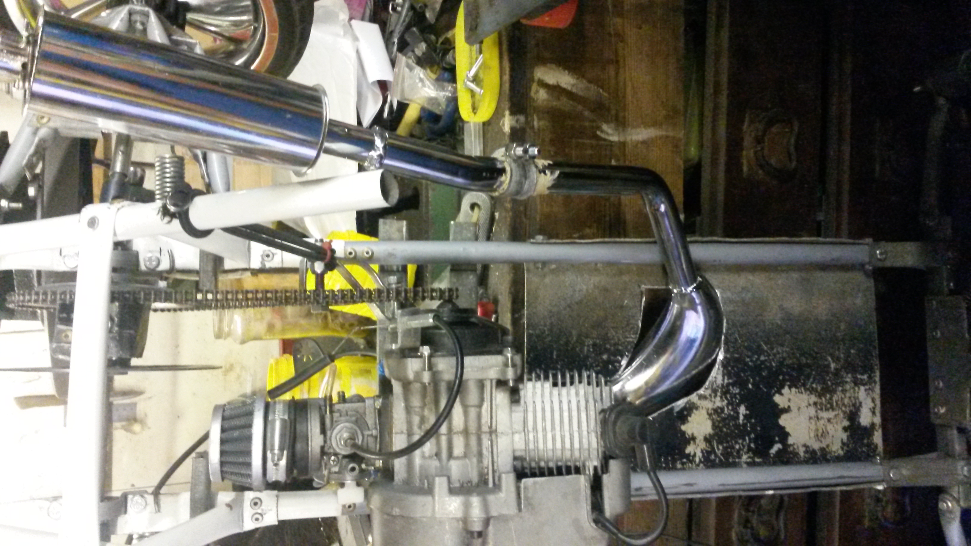 I used exhaust assembly paste to create a seal at each joint. I made my own clamps and although they're not pretty they do do the job very well.
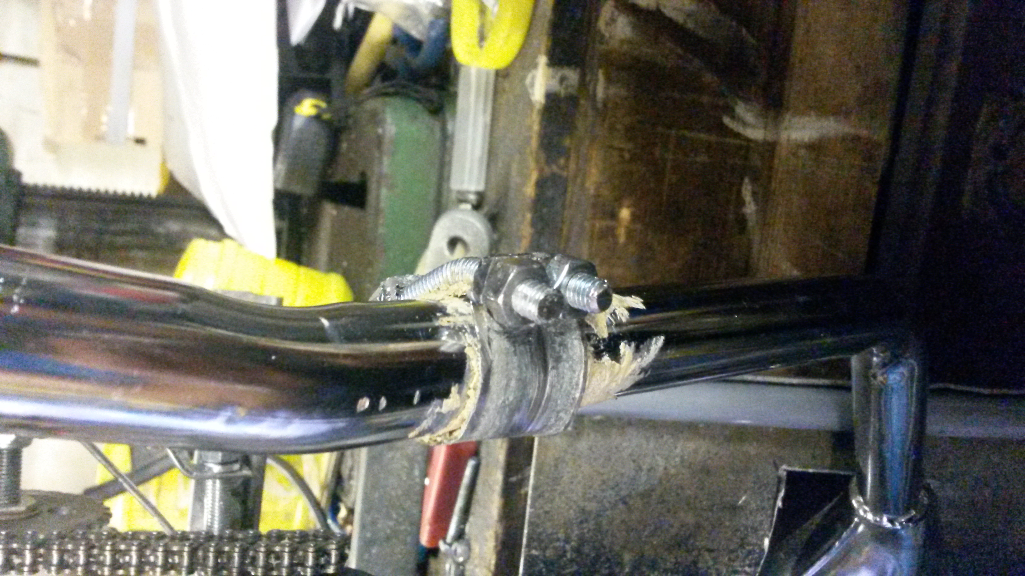
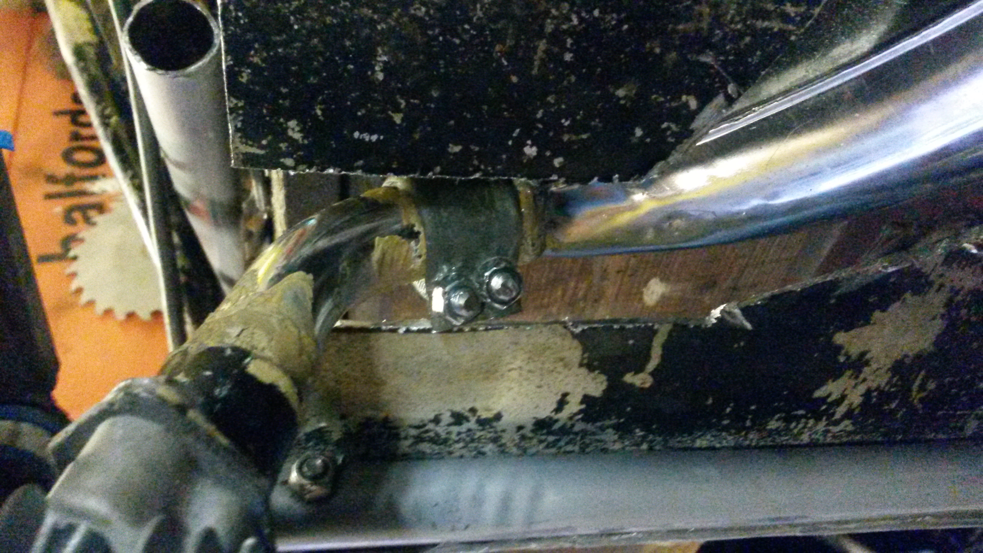
As you can see I had to make a cut out in the floor pan because the exhaust angle causes the expansion chamber to dip below floor pan level. I'll tidy up the cut out in time but it'll be fine for now.
This is where the rear springs are going
And this is where the gas struts will be placed
That's it for now, I'll be working on it today so I hope I have something more to show you.
I have some more progress with the car however, the exhaust is reassembled and mounted
As you can see I had to make a cut out in the floor pan because the exhaust angle causes the expansion chamber to dip below floor pan level. I'll tidy up the cut out in time but it'll be fine for now.
This is where the rear springs are going
And this is where the gas struts will be placed
That's it for now, I'll be working on it today so I hope I have something more to show you
.
08-15-2015, 11:18 AM
#13
Member
Thread Starter
Join Date: Apr 2015
Posts: 42
Likes: 0
Received 0 Likes
on
0 Posts
Mounted the rear shocks today, I consider myself very lucky in that the gas struts seem to work extremely well with the trampoline springs  . It doesn't look like much from this angle but seen from the side it looks quite good aesthetically. I think I'll add a spoiler to hide some of the shock mount once I've built up the roll cage at the rear.
. It doesn't look like much from this angle but seen from the side it looks quite good aesthetically. I think I'll add a spoiler to hide some of the shock mount once I've built up the roll cage at the rear.
 08-15-2015, 02:56 PM
#16
Member
Thread Starter
Join Date: Apr 2015
Posts: 42
Likes: 0
Received 0 Likes
on
0 Posts
I don't understand it, it's not like I'm hanging upside down to take the pictures lol. They're all the right way up on the laptop then I upload them and they get screwed up for some reason :/.
08-17-2015, 11:05 AM
#17
Member
Thread Starter
Join Date: Apr 2015
Posts: 42
Likes: 0
Received 0 Likes
on
0 Posts
I now have a rolling chassis!


I'm starting to have doubts about the wheels now I've seen it sitting on them. the front track is slightly wider than the back but that's no problem. I think I'll have to tension the front springs more as the suspension is a little soft and I've still got maybe one and a half pounds of motors, electronics and lead acid battery to install lol. The front and rear shock towers are going to be trimmed to mske them look prettier and I'll be making some panels for the cage out of aluminium plate. This is one heavy sucker, I sure hope I don't run into anybody's ankles with it lol. Oh and the wheels look a little crooked because the suspension is working and it's on an uneven surface lol.
I'm starting to have doubts about the wheels now I've seen it sitting on them. the front track is slightly wider than the back but that's no problem. I think I'll have to tension the front springs more as the suspension is a little soft and I've still got maybe one and a half pounds of motors, electronics and lead acid battery to install lol. The front and rear shock towers are going to be trimmed to mske them look prettier and I'll be making some panels for the cage out of aluminium plate. This is one heavy sucker, I sure hope I don't run into anybody's ankles with it lol. Oh and the wheels look a little crooked because the suspension is working and it's on an uneven surface lol.
Last edited by superchip; 08-17-2015 at 11:19 AM.
08-17-2015, 12:13 PM
#18

Join Date: Jan 2009
Location: Close to the beach, AUSTRALIA
Posts: 3,497
Likes: 0
Received 0 Likes
on
0 Posts
Looking good.
Yeh you should probably add as much bracing as you can, seeing as nothing is welded together.
Aluminium sheet is good.
Once you get this thing moving it'll start twisting and flexing.
It's a vicious cycle with homebuilt RC cars.
Stronger -> heavier -> more moving mass -> more damage on impact....
Cutting bits off the exhaust will alter the performance but in the scheme of things it probably won't make much difference.
I had a link to a webpage where a guy drilled a couple of holes in the clutch shoes to make them lighter = higher RPM on engagement.
Stronger springs can also be added.
The idea for reverse is something I toyed around with as well years ago.
One thing I looked at, but never tried was using bits from an outboard boat motor.
They have a gear setup which should be possible to use in an RC car for reverse.
What are you going to use for a steering servo?
Home made monster servo?
I've steered some rather heavy cars with a Hitec HS 805BB.
A few things to consider with th front end setup is camber and caster.
Also look up "Ackermann angle".
Easy to work out and maks a world of difference.
Most of my projects were very crude and simple, but they always turned on a dime.
Have a dig throuh here: https://m.youtube.com/user/hairyalien for vids of some of my projects.
I had some lengthy threads on them here on the forum but I think I've since deleted most of the Photobucket pics as I ran out of storage space.
Last edited by Dirty_Vinylpusher; 08-17-2015 at 12:58 PM.
08-17-2015, 02:37 PM
#19
Member
Thread Starter
Join Date: Apr 2015
Posts: 42
Likes: 0
Received 0 Likes
on
0 Posts
Yeah I've been thinking how well the rivets will hold up. It's not held together purely with rivets though, there are bolts holding the important bits together too, I'll also replace some of the rivets on the roll cage and shock mounts with bolts also as I've just used rivets on some parts to temporarily hold them together. Given how thin the tubing is I'm using, I think welding it wouldn't work as I reckon it would just melt through.
For the steering servo yes I am indeed using the wiper motor servo now I know what I was doing wrong lol. I also have a smaller wiper motor which I'm going to use for the throttle/brake servo. I have to confess to not even thinking about the Ackerman angle but the turn buckles I'm using plus the angle I'm going to have the tie rods at should provide this. The front end is set up with some positive camber but no castor seeing as I'm using a wiper motor I don't think I'd need that feature in the steering. The rear has some positive camber too but once moving the suspension should settle and both wheels should end up on the negative camber side of near vertical.
The engine is bog standard for now but once it's running the way I like I'll start upgrading engine parts. I have a rocket key to advance the timing and I'll buy a better carb and Reed valve and maybe a better exhaust too. I only cut about two inches off the overall length of the exhaust but i have increased the distance between the expansion chamber to the exhaust port not out of gaining performance but to make it fit better lol. Not sure about drilling holes in the clutch shoes, I'll look into that when the time comes, same goes for the clutch springs.
I was thinking of using the guts from a cordless drill for the reverse actuated by a normal servo, with a small sprocket in the chuck to engage with the chain. Once the sprocket is engaged, the drill button is pressed by the linkage of the reverse mechanism to start the motor. Make sense? Lol.
Many thanks for all the info though, I'll definitely look at your builds .
For the steering servo yes I am indeed using the wiper motor servo now I know what I was doing wrong lol. I also have a smaller wiper motor which I'm going to use for the throttle/brake servo. I have to confess to not even thinking about the Ackerman angle but the turn buckles I'm using plus the angle I'm going to have the tie rods at should provide this. The front end is set up with some positive camber but no castor seeing as I'm using a wiper motor I don't think I'd need that feature in the steering. The rear has some positive camber too but once moving the suspension should settle and both wheels should end up on the negative camber side of near vertical.
The engine is bog standard for now but once it's running the way I like I'll start upgrading engine parts. I have a rocket key to advance the timing and I'll buy a better carb and Reed valve and maybe a better exhaust too. I only cut about two inches off the overall length of the exhaust but i have increased the distance between the expansion chamber to the exhaust port not out of gaining performance but to make it fit better lol. Not sure about drilling holes in the clutch shoes, I'll look into that when the time comes, same goes for the clutch springs.
I was thinking of using the guts from a cordless drill for the reverse actuated by a normal servo, with a small sprocket in the chuck to engage with the chain. Once the sprocket is engaged, the drill button is pressed by the linkage of the reverse mechanism to start the motor. Make sense? Lol.
Many thanks for all the info though, I'll definitely look at your builds
.
08-18-2015, 09:43 AM
#20
Member
Thread Starter
Join Date: Apr 2015
Posts: 42
Likes: 0
Received 0 Likes
on
0 Posts
Been sorting out some steering linkage today. It all has to made from scratch so progress is slow, regardless I have made up the tie rods and about 80% of the linkage so it should be finished tomorrow. With what small tests I could do in it's current state I believe I have achieved some Ackerman angle at both locks, whether it's going to be enough remains to be seen. I also plan to make some bump stops for the turn buckles so as to prevent any steering overthrow.
I've been thinking of bumpers too. what I was thinking is to make them spring loaded to help prevent,or at least minimise, the chassis from getting bent. They also have to provide some protection to the wish bones but not too long so that the car looks like a dodgem lol. It only needs one at the front really because on the maiden drive it will only be able to go forwards, I'll attempt the reverse after it is ruuning good. More to come.
I've been thinking of bumpers too. what I was thinking is to make them spring loaded to help prevent,or at least minimise, the chassis from getting bent. They also have to provide some protection to the wish bones but not too long so that the car looks like a dodgem lol. It only needs one at the front really because on the maiden drive it will only be able to go forwards, I'll attempt the reverse after it is ruuning good. More to come.
08-18-2015, 02:32 PM
#21
Join Date: Jan 2009
Location: Close to the beach, AUSTRALIA
Posts: 3,497
Likes: 0
Received 0 Likes
on
0 Posts
I always found the steering the most fun part of building RC cars.
Yeh, it will handle and steer just fine with "everything at zero", so to speak = no camber, caster, toe in/out etc.
Get it rolling first and make adjustments later.
Gaaah, this makes me wanna build another car.
Just have way too many other things to do at the moment haha.
Yeh, it will handle and steer just fine with "everything at zero", so to speak = no camber, caster, toe in/out etc.
Get it rolling first and make adjustments later.
Gaaah, this makes me wanna build another car.
Just have way too many other things to do at the moment haha.
Last edited by Dirty_Vinylpusher; 08-18-2015 at 02:41 PM.
08-18-2015, 03:01 PM
#22
Member
Thread Starter
Join Date: Apr 2015
Posts: 42
Likes: 0
Received 0 Likes
on
0 Posts
Exactly, even when it's rolling under its own stream there is going to be loads of things to improve, adjust or change. You can't just set a thing this size on the ground and brum it about lol.
I think I'm secretly stretching out finishing the fabrication because I absolutely hate electronics although I'm going to have to face it soon lol.
I've realised that it'll be a bit tight to fit two widow wiper motors in the space they're going because the bigger one is a beast so I've ordered another small wiper motor exactly the same as the one I'm going to use for the throttle/brake function. This will allow both motors to fit where I want them and allow plenty of air flow because these things get warm, plus despite their smaller size they still give monstrous torque, more than this project needs, still nice to know the power is there when I need it though.
I agree, once you get your teeth into a project you both want to see it to the end and not at the same time, what am I going to do with myself once it's finished? Hahaha. Oh, I now! I've still got a 1/8 scale model I want to start. Here's a hint, it's going to be using kyosho mad force axles .
Hopefully I'll have the linkage finished tomorrow with some pics to show what I did.
I think I'm secretly stretching out finishing the fabrication because I absolutely hate electronics although I'm going to have to face it soon lol.
I've realised that it'll be a bit tight to fit two widow wiper motors in the space they're going because the bigger one is a beast so I've ordered another small wiper motor exactly the same as the one I'm going to use for the throttle/brake function. This will allow both motors to fit where I want them and allow plenty of air flow because these things get warm, plus despite their smaller size they still give monstrous torque, more than this project needs, still nice to know the power is there when I need it though.
I agree, once you get your teeth into a project you both want to see it to the end and not at the same time, what am I going to do with myself once it's finished? Hahaha. Oh, I now! I've still got a 1/8 scale model I want to start. Here's a hint, it's going to be using kyosho mad force axles
. Hopefully I'll have the linkage finished tomorrow with some pics to show what I did
.
08-18-2015, 07:37 PM
#23
Join Date: Jan 2009
Location: Close to the beach, AUSTRALIA
Posts: 3,497
Likes: 0
Received 0 Likes
on
0 Posts
Yeh the building and problem solving is what I enjoy the most with everything I do.
Once it's 98% done and I know it works it's no fun anymore haha.
Most of my builds only got driven once or twice then pulled apart to build the next one.
Some never made it past half finished....quite a few actually.
It's the same with most other things I'm working on.
I really should build another car though, as I've now got a better welder, am much better at welding and also have a bunch of other tools and tricks which would come in handy.
I think if I do build another it will be something stupid with lawnmower motor and close to 1/2 or 1/3 scale.
mmmm
08-19-2015, 12:25 AM
#24
Member
Thread Starter
Join Date: Apr 2015
Posts: 42
Likes: 0
Received 0 Likes
on
0 Posts
If you do choose to build something that big I would put a motorcycle engine in it personally. When I was still in the planning stage of this build I was thinking of using a 110cc quad engine, purely because it had four forward gears and reverse but it also meant I wasn't as limited to weight. That was when I still hadn't perfected the wiper servo though so I decided against it. Wish I used one now lol.
I'm kinda like you in the respect that I tend to lose interest in a project once it's built, the building part is definitely the fun part, actually driving your creation is good at first but miss it being on the slab lol. You almost wish something breaks do you can rip it apart haha.
I wish I could weld, this is something I really have to master before I can make something that I'll be 100% happy with, in the meantime though I'll just have to make do with rivets and bolts lol.
08-19-2015, 10:22 AM
#25
Member
Thread Starter
Join Date: Apr 2015
Posts: 42
Likes: 0
Received 0 Likes
on
0 Posts
Finished the steering linkage  or rather, almost finished lol. I started late today so only managed what you see. I need to secure the linkage at the top so it can't bend the floor pan.
I believe I have some Ackerman angle
 , I don't know if I have any bump steer yet because I forgot to check lol. I don't think I'll bother with a servo saver, mainly because I'd have to make one and wouldn't know where to implement it on my set up. Plus there�s not much room for fancy servo savers anyhow, I don't know, I might make one further down the line as I know how important they are. In fact as I'm typing I've just thought if I get a strong spring and fit it between the servo horn and the linkage that might suffice. My mind is always working on the buggy even though I'm not there physically lol. Next I think is to finally mount the steering servo so I'll tackle that tomorrow. More to come
I believe I have some Ackerman angle
Last edited by superchip; 08-19-2015 at 10:36 AM.