


The New F86D Dog Sabre
 10-21-2013, 05:19 AM
#951


Join Date: Jan 2006
Location: Colorado Springs,
CO
Posts: 530
Likes: 0
Received 0 Likes
on
0 Posts
Yes, the wood in my nose gear mount rails was not that great, either. I think what you have done should be more than sufficient. I notice the ply cross brace at the top of the fuselage is not aligned either - I had the same problem. Ended up cutting it out and reinstalling with a brace or two. Good job and good luck!
Regards,
Gus
Regards,
Gus
 12-28-2013, 05:57 PM
#952


I must be the last person in RC building one of these F86 Modellbau Dog Sabers, but I'll share anyway. I haven't done much on mine until the Christmas vacation break from work. I also took a whole summer off learning all about helicopters. Crashing and rebuilding. I really hit a roadblock on the exhaust tube install. I know this kit is an entry level jet, but the techniques and planning required to put the tube in is anything but entry level. I started with the assumption that the tube is already the correct length, I wanted to leave P1 in one piece, and I wanted about .6" gap from exhaust tip to tube. I quickly discovered the engine rails are too close together to fit the K80, so they needed to be trimmed. I used a dremel, but the vibration made the glue joints come apart alarmingly quickly and the rails just fell out!! So, I finished the trimming on the band saw, and re-glued the engine rails back in. This kit needs extra reinforcement, IMHO. If it was anything but free, I'd write far more scathing comments.
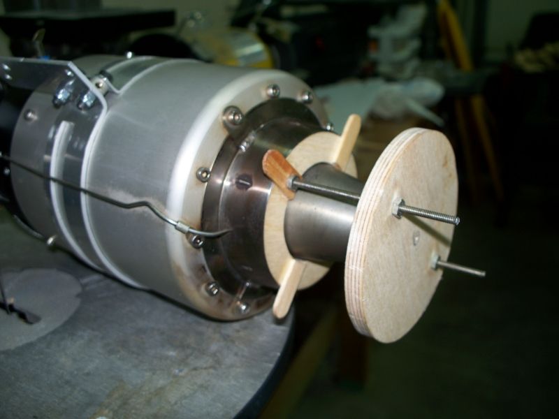
You've ALL been thru this exhaust tube install already, so I feel a little like those new parents who enthusiastically share their baby experiences and discoveries like no one has every had a kid before. Yawn! Well, I think I did something a little new, with this combo alignment AND spacing plug I made.
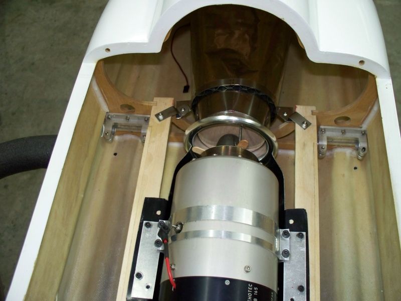
The real issue though is how to install that pesky P1 former without cutting it up. It seems there no room to work, and no way to assemble it. I even had a new access hatch in the bottom of the fuselage all mapped out to cut. Well, I didn't do it, but it was close. So I put the P1 former in where it will live, leaving it loose of course, then forced the stainless tube through it, in place. It bent egg shaped as it passed thru the loose P1, but popped back round once it was past the double wall. Then, I installed the engine (K80) with my alignment/spacer plug between, forcing the tube into the center, and carrying the loose P1 into place by default. Adjust everything fore or aft to stick the exhaust tube out the back about 1/8" at the top. Next, I used a long bent wire to pull P1 vertical, and up against the stainless mounting tabs. Using a long stick, I dapped epoxy in places to tack the tabs and the P1 former to the fuselage. Then, I removed the engine and finished the epoxy fillets all around, top and bottom as the pictures show. Lastly, I made a REALLY long drill and drilled the two screw holes that hold the stainless steel tabs to the P1 former. I drilled thru the front intake opening. So, it's all done, and the engine is installed. I'd love to hear more exhaust tube horror stories, if you care to share.


You've ALL been thru this exhaust tube install already, so I feel a little like those new parents who enthusiastically share their baby experiences and discoveries like no one has every had a kid before. Yawn! Well, I think I did something a little new, with this combo alignment AND spacing plug I made.
The real issue though is how to install that pesky P1 former without cutting it up. It seems there no room to work, and no way to assemble it. I even had a new access hatch in the bottom of the fuselage all mapped out to cut. Well, I didn't do it, but it was close. So I put the P1 former in where it will live, leaving it loose of course, then forced the stainless tube through it, in place. It bent egg shaped as it passed thru the loose P1, but popped back round once it was past the double wall. Then, I installed the engine (K80) with my alignment/spacer plug between, forcing the tube into the center, and carrying the loose P1 into place by default. Adjust everything fore or aft to stick the exhaust tube out the back about 1/8" at the top. Next, I used a long bent wire to pull P1 vertical, and up against the stainless mounting tabs. Using a long stick, I dapped epoxy in places to tack the tabs and the P1 former to the fuselage. Then, I removed the engine and finished the epoxy fillets all around, top and bottom as the pictures show. Lastly, I made a REALLY long drill and drilled the two screw holes that hold the stainless steel tabs to the P1 former. I drilled thru the front intake opening. So, it's all done, and the engine is installed. I'd love to hear more exhaust tube horror stories, if you care to share.
Last edited by Pull Up Now!; 12-28-2013 at 06:08 PM.
 12-28-2013, 08:39 PM
#954

I must be the last person in RC building one of these F86 Modellbau Dog Sabers, but I'll share anyway. I haven't done much on mine until the Christmas vacation break from work. I also took a whole summer off learning all about helicopters. Crashing and rebuilding. I really hit a roadblock on the exhaust tube install. I know this kit is an entry level jet, but the techniques and planning required to put the tube in is anything but entry level. I started with the assumption that the tube is already the correct length, I wanted to leave P1 in one piece, and I wanted about .6" gap from exhaust tip to tube. I quickly discovered the engine rails are too close together to fit the K80, so they needed to be trimmed. I used a dremel, but the vibration made the glue joints come apart alarmingly quickly and the rails just fell out!! So, I finished the trimming on the band saw, and re-glued the engine rails back in. This kit needs extra reinforcement, IMHO. If it was anything but free, I'd write far more scathing comments.
You've ALL been thru this exhaust tube install already, so I feel a little like those new parents who enthusiastically share their baby experiences and discoveries like no one has every had a kid before. Yawn! Well, I think I did something a little new, with this combo alignment AND spacing plug I made.
The real issue though is how to install that pesky P1 former without cutting it up. It seems there no room to work, and no way to assemble it. I even had a new access hatch in the bottom of the fuselage all mapped out to cut. Well, I didn't do it, but it was close. So I put the P1 former in where it will live, leaving it loose of course, then forced the stainless tube through it, in place. It bent egg shaped as it passed thru the loose P1, but popped back round once it was past the double wall. Then, I installed the engine (K80) with my alignment/spacer plug between, forcing the tube into the center, and carrying the loose P1 into place by default. Adjust everything fore or aft to stick the exhaust tube out the back about 1/8" at the top. Next, I used a long bent wire to pull P1 vertical, and up against the stainless mounting tabs. Using a long stick, I dapped epoxy in places to tack the tabs and the P1 former to the fuselage. Then, I removed the engine and finished the epoxy fillets all around, top and bottom as the pictures show. Lastly, I made a REALLY long drill and drilled the two screw holes that hold the stainless steel tabs to the P1 former. I drilled thru the front intake opening. So, it's all done, and the engine is installed. I'd love to hear more exhaust tube horror stories, if you care to share.
 12-28-2013, 08:46 PM
#955
The mounting of that former is fiddly and time consuming - nothing more.
Would I have designed it differently?......DUH! But since I didn't - just had to accept it and move on.
Greg
12-29-2013, 04:03 AM
#956
Right Jetflyr, the rounded opening is riveted. Took the words right out of my bell mouth. Even the if bellmouth WAS bolted, can you imagine trying to put the screws back in and tightening them working down and aft in that little hole? With the P1 former and the thrust pipe in your hands, it's not immediately apparent that you CAN slide the pipe through the former since the hole in P1 is smaller than the pipe diameter. It deforms the pipe and you have to force it through. One doesn't want to ruin the pipe, and the instructions don't say the pipe will pop back into shape like it apparently does.
Countryboy, thanks for sharing your wood alignment jig photos from the 3-14-2010 Jet Legend F-4 thread, post #163. The idea was new to me, anyhow. Question: Does your plug set just the alignment and not set the gap from the end of the engine to the beginning of the exhaust tube? Mine bottoms out flush with the thrust pipe bellmouth so it sets the gap automatically(notice it's tapered). This is needed on the Saber Dog because there's no access to the area to measure it. Your F4 has amazing access to the area in question compared to this Saber Dog where one is working not only down in the access hole, but offset aftwards one set of formers.
Countryboy, thanks for sharing your wood alignment jig photos from the 3-14-2010 Jet Legend F-4 thread, post #163. The idea was new to me, anyhow. Question: Does your plug set just the alignment and not set the gap from the end of the engine to the beginning of the exhaust tube? Mine bottoms out flush with the thrust pipe bellmouth so it sets the gap automatically(notice it's tapered). This is needed on the Saber Dog because there's no access to the area to measure it. Your F4 has amazing access to the area in question compared to this Saber Dog where one is working not only down in the access hole, but offset aftwards one set of formers.
12-29-2013, 07:45 AM
#957
As I mentioned before, I'm new to turbines. I have a gas tank plumbing question. The Saber Dog comes with two tanks, and the instructions are vague on tube routing. I've read the tanks should be routed in series though. So, just to clarify, should only the last tank in the series be vented? So, the routing goes to VAT, then first tank (no vent), then on to the last tank in the series which IS vented? Thanks for advise!
12-29-2013, 09:39 AM
#958
As I mentioned before, I'm new to turbines. I have a gas tank plumbing question. The Saber Dog comes with two tanks, and the instructions are vague on tube routing. I've read the tanks should be routed in series though. So, just to clarify, should only the last tank in the series be vented? So, the routing goes to VAT, then first tank (no vent), then on to the last tank in the series which IS vented? Thanks for advise!
Get the review in Model Aviation - their online version has lots of photos including the routing.
Greg
12-29-2013, 01:28 PM
#960
12-29-2013, 03:07 PM
#961
Drat! I can't view it. I have no access to the digital edition unless I pay $9.95 to them. I opted for the print-only edition. Seems like I already paid them enough money over the years to build a fancy flying site I'll never use.  . Thanks anyway though Jetflyr!
. Thanks anyway though Jetflyr!
12-29-2013, 05:58 PM
#969
My Feedback: (18)
Join Date: Mar 2005
Location: Pembroke Pines, FL
Posts: 108
Likes: 0
Received 0 Likes
on
0 Posts
I must say, I had a blast with mine. It was my first Turbine "trainer" aircraft and I do not regret building and flying it. Yes there were some issues that needed to be solved in the construction but come on now, your not even paying $700.00 for this aircraft. If you want something that goes together with little or no issues go out and spend $4k in a BVM Bobcat or Bandit. This Aircraft fit's the bill for the first time turbine pilot or someone who wants to stay within a budget and does not want to worry about having +6k or more in the air.
12-29-2013, 07:14 PM
#971
Jetflyr--I figured out why MA wouldn't let me view the F-86D review. It wasn't the $9.95 after all. You have to specifically link your modelaircraft.org login with the modelaviation.com site. I just discovered this by clicking around in there as there was no clear indication. Anyway, I have the review now, and I'm reading it. Thanks again.
12-30-2013, 02:09 AM
#972
Member
Join Date: Mar 2009
Location: Dudelange, LUXEMBOURG
Posts: 67
Likes: 0
Received 0 Likes
on
0 Posts
Hi,
I use both fuel cells in parallel. Just take care, that all lines have the same lenght. No problem with different fuel levels on buth sides. I prefer this setup to make the fuel pump work less. Eventually you need less charge an the turbine batterie.
Flilek
I use both fuel cells in parallel. Just take care, that all lines have the same lenght. No problem with different fuel levels on buth sides. I prefer this setup to make the fuel pump work less. Eventually you need less charge an the turbine batterie.
Flilek
12-30-2013, 08:32 AM
#973
Join Date: Jan 2006
Location: Colorado Springs,
CO
Posts: 530
Likes: 0
Received 0 Likes
on
0 Posts
This is a schematic of how I did mine with the KT-80. There may be some extraneous info here related to the KT-80-F, but the plumbing is correct.
Regards,
Gus
12-30-2013, 09:48 AM
#975
Gus (Mtnflyr), thanks for the great photos, and the plumbing diagram. Interesting divergence of thought on how to plumb the tanks! Have any of the folks in the parallel school of thought had any issues with uneven fuel usage between the two tanks? If parallel, it seems like it would be best to locate the Y connector between the two as close the the tanks as possible to minimize any differences in flow rate. Also, the Greg Moore review didn't offer any info on tank plumbing. I know Joe Grice, he lives near here. I'll shoot him an email about plumbing just for kicks. Lots of people recommend Hysol 9462, which just seems like structural epoxy. How do you say JB Weld???  Anyway, seriously the cost is TEN TIMES what 30 minute epoxy is. Add microbaloons for viscosity if needed. The Greg Moore article says that goop is ok, too. Or even plain old silicone caulk.
For the vent, on gasoline engines I've always terminated the vent line with one of these TME check valves. They completely prevent leaks inside the plane, and take no pressure at all to draw fuel through because they contain a flapper reed valve. It's not the ball-and-spring affair where the fuel draw has to overcome the spring tension. Does anyone see any issue with using these for turbines, to terminate the vent(s)?
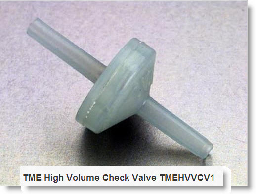
Anyway, seriously the cost is TEN TIMES what 30 minute epoxy is. Add microbaloons for viscosity if needed. The Greg Moore article says that goop is ok, too. Or even plain old silicone caulk.For the vent, on gasoline engines I've always terminated the vent line with one of these TME check valves. They completely prevent leaks inside the plane, and take no pressure at all to draw fuel through because they contain a flapper reed valve. It's not the ball-and-spring affair where the fuel draw has to overcome the spring tension. Does anyone see any issue with using these for turbines, to terminate the vent(s)?
Last edited by Pull Up Now!; 12-30-2013 at 09:58 AM. Reason: add picture