


Maj. Woody's X-Treme Jets F-4C Phantom

 02-17-2019, 09:53 AM
#1202

My Feedback: (11)

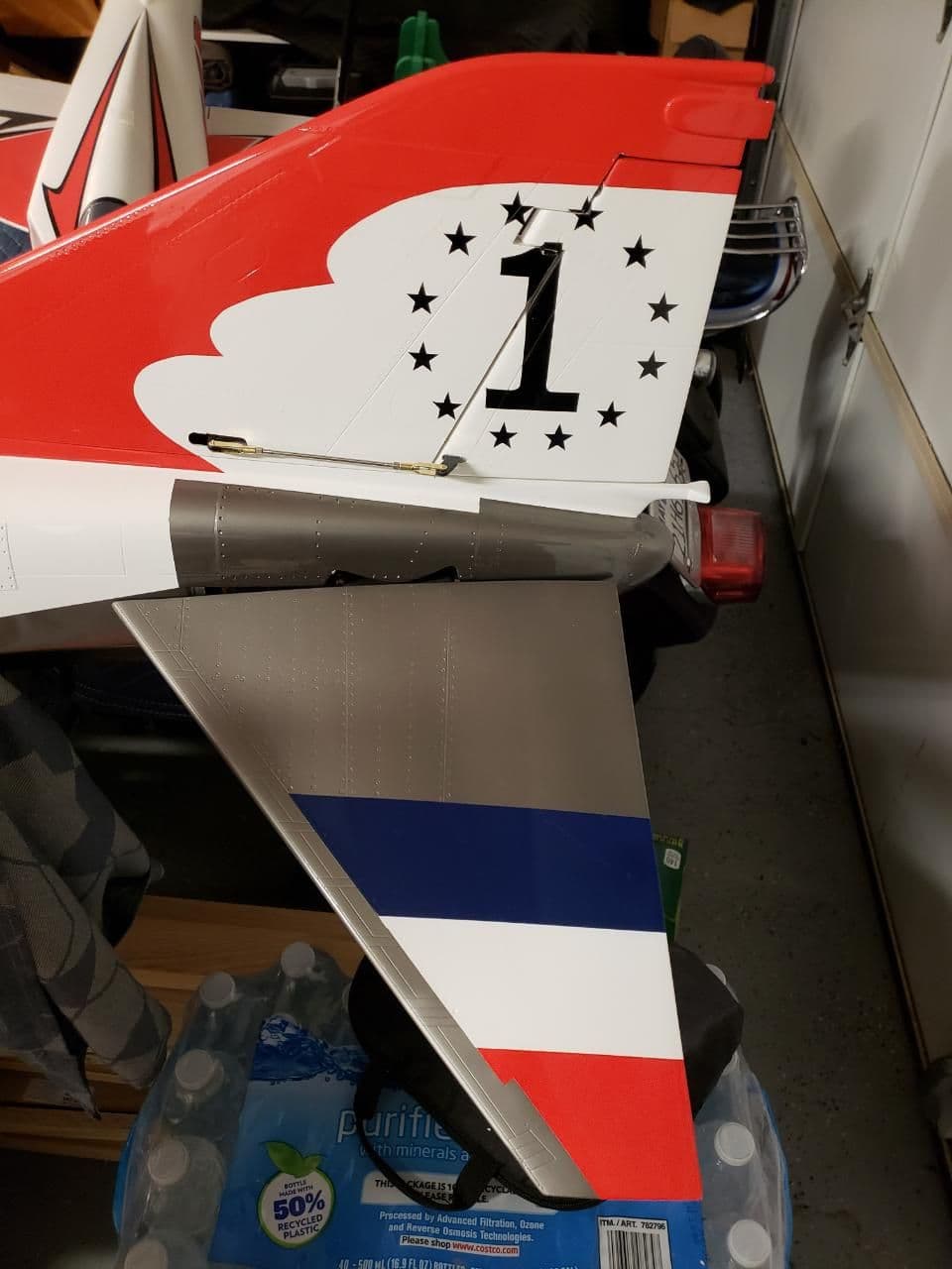


I made some progress the last couple days. I had to remove the rudder and reinstall to eliminate too much slop. On the back of the fin I added 3/16" plywood to give the hinges better support and keep the rudder in position for the painted markings. I will need to sand trailing edge of rudder to line up better. Overall I am happy with the fix and now the rudder has minimal slop from the servo gears.
Setup the stabilator mechanism and really happy with the Savox 1230 single servo. Plenty of power and stabilator has nice solid feel.
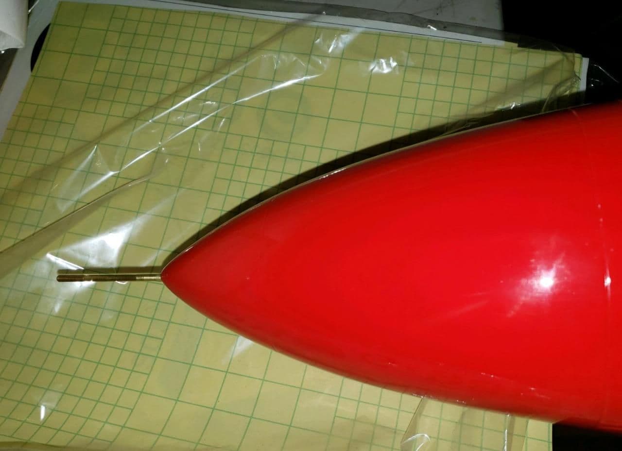
Installed pitot tube in the nose. This was fun since the nose does not come off and I cannot reach my hand all the way in. Ended up using a wire and inserted through the drilled hole then used shrink tubing to attach wire to pitot tube. Once attached I pulled back through the hole and glued in place. Worked excellent and looks good.
Next I setup the steering servo and installed the nose gear. I initially wanted to use the Savox 1250mg servo but it does not fit the servo bracket length wise. If I adjusted the opening it would have went into the mounting holes. Ended up using the Hitec 225mg servo (Thank you Joe). Still had to adjust the opening, but it was width wise instead of length. Nose gear setup is installed and I used blind nuts instead of lock nuts. Easier to install and remove as needed.
Really enjoying this build, and looking forward to more progress today.
02-19-2019, 05:58 PM
#1203
My Feedback: (11)
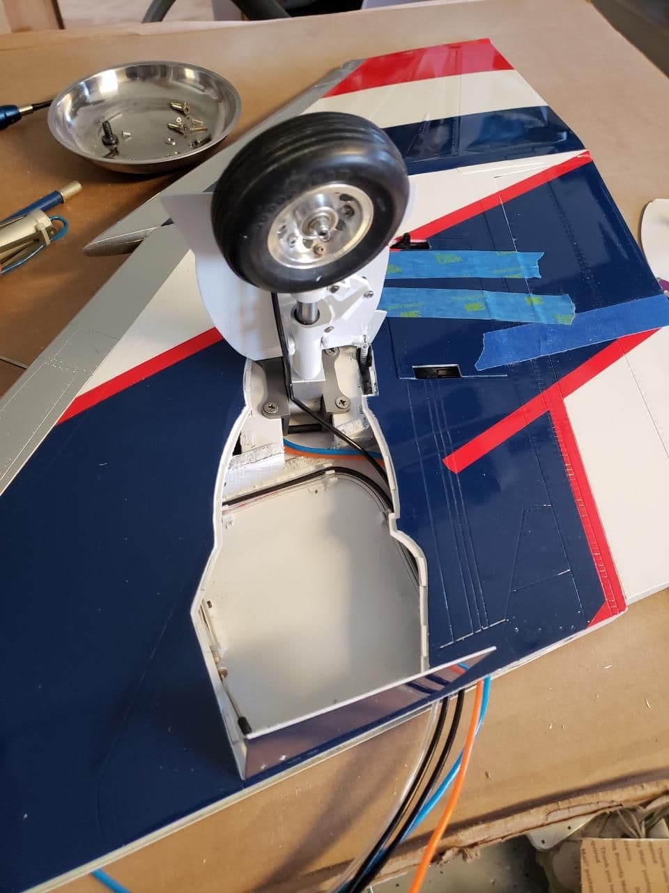
I made some more progress yesterday and today. Painted the main gear wheel wells and installed aileron and flap servos (need to still install control horns and rods). Reinstalled main gear and door hardware. Made sure gear struts are mounted the correct way since manufacturer had incorrectly installed them.
i am travelling for work the next few days, so not going to do more until the weekend.
Thank you for looking.
Jeff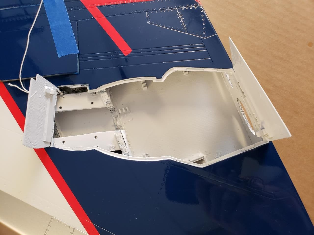

i am travelling for work the next few days, so not going to do more until the weekend.
Thank you for looking.
Jeff

 02-25-2019, 07:43 AM
#1205

My Feedback: (48)
Jeff,
To be honest I couldn't tell from the instructions which way was what for the pipe. Just install it to get the maximum amount of downthrust. You want to make sure that the exhaust blast is directed away from the stabilizer.
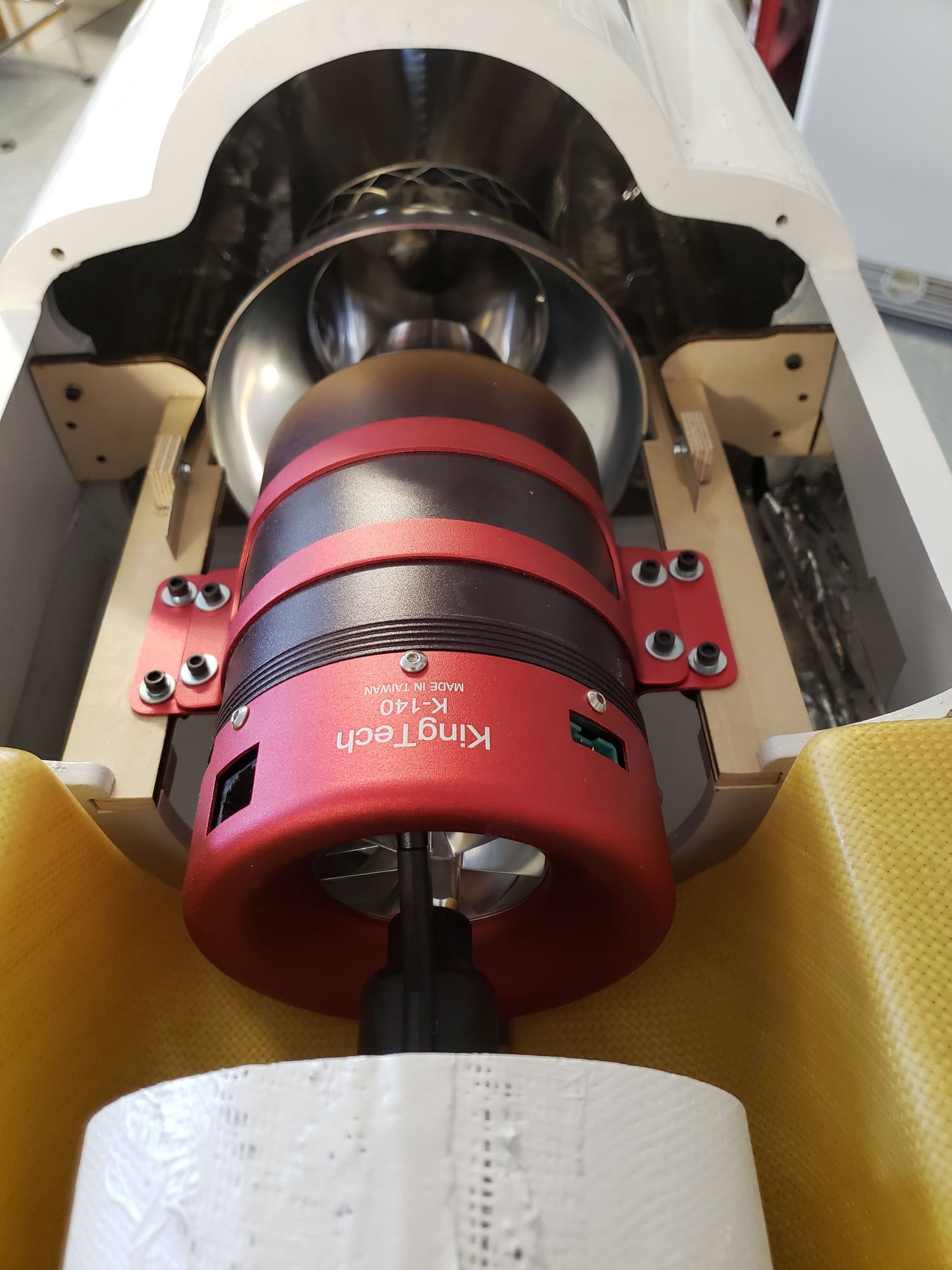
Check to see what Kingtech recommends for pipe clearance. In general you'll the end of the engine tailcone to be about one inch before the front of the pipe (not including the bellmouth). Here's a picture of mine for reference.
Joe
To be honest I couldn't tell from the instructions which way was what for the pipe. Just install it to get the maximum amount of downthrust. You want to make sure that the exhaust blast is directed away from the stabilizer.
Check to see what Kingtech recommends for pipe clearance. In general you'll the end of the engine tailcone to be about one inch before the front of the pipe (not including the bellmouth). Here's a picture of mine for reference.
Joe
02-25-2019, 08:12 AM
#1206
My Feedback: (11)
Joe,
Thank you for the response. I will adjust for maximum down thrust. I see your turbine sits above and further forward on the tanks. I am going to see if I can raise my turbine to do same. It currently hits the top rear edge of the tanks.
Did you trim the intake down? Mine looks to extend more aft than yours.
Also fuel tank question. Did you mount the tank hardware on the front of the main tanks? It seems it would interfere with the side intakes.
Thank you,
Jeff
02-25-2019, 01:24 PM
#1207
My Feedback: (48)
Don't raise the turbine! Read post #1033. If you look carefully at my picture you'll see that there is about a 1" space between the saddle tanks at the bottom (I just used a balsa block as a spacer). This pushes the tanks a bit outward and upward. Now the tanks sit about 3/4 to 1 '' above the hatch flanges, so you have to trim the hatch flange in order for the hatch to fit properly.
Once you install the fuel bungs and tubing you won't be able to get the tanks in unless you shorten the inlet. You can't put the tank hardware where Skymaster puts the openings. You have to plug their opening and carefully re-locate it. It's a tight fit and there's only one spot that will work. See post #1023. Also it's not necessary to do major surgery or to replace the main tank as some did. Just re-locate the opening to about 1/3 up from the bottom.
Once you install the fuel bungs and tubing you won't be able to get the tanks in unless you shorten the inlet. You can't put the tank hardware where Skymaster puts the openings. You have to plug their opening and carefully re-locate it. It's a tight fit and there's only one spot that will work. See post #1023. Also it's not necessary to do major surgery or to replace the main tank as some did. Just re-locate the opening to about 1/3 up from the bottom.
02-25-2019, 04:31 PM
#1208
My Feedback: (11)
Joe,
I really appreciate the assistance. I will do as you mention. Also, I ordered my tanks without the holes drilled so I can locate the hardware where ever needed.
The post with the hardware 1/3 up the tank perfect sense. I will do that as well.
Thanks,
Jeff
I really appreciate the assistance. I will do as you mention. Also, I ordered my tanks without the holes drilled so I can locate the hardware where ever needed.
The post with the hardware 1/3 up the tank perfect sense. I will do that as well.
Thanks,
Jeff
Don't raise the turbine! Read post #1033. If you look carefully at my picture you'll see that there is about a 1" space between the saddle tanks at the bottom (I just used a balsa block as a spacer). This pushes the tanks a bit outward and upward. Now the tanks sit about 3/4 to 1 '' above the hatch flanges, so you have to trim the hatch flange in order for the hatch to fit properly.
Once you install the fuel bungs and tubing you won't be able to get the tanks in unless you shorten the inlet. You can't put the tank hardware where Skymaster puts the openings. You have to plug their opening and carefully re-locate it. It's a tight fit and there's only one spot that will work. See post #1023. Also it's not necessary to do major surgery or to replace the main tank as some did. Just re-locate the opening to about 1/3 up from the bottom.
Once you install the fuel bungs and tubing you won't be able to get the tanks in unless you shorten the inlet. You can't put the tank hardware where Skymaster puts the openings. You have to plug their opening and carefully re-locate it. It's a tight fit and there's only one spot that will work. See post #1023. Also it's not necessary to do major surgery or to replace the main tank as some did. Just re-locate the opening to about 1/3 up from the bottom.
03-10-2019, 02:19 PM
#1209
My Feedback: (11)
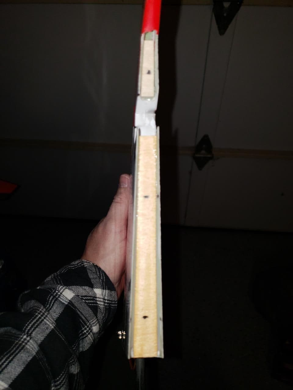
Back to working on the F4. I seem to have run into another small issue. Skymaster forgot to send the wood inserts for the tail cones. They sent them later and now I am at the stage to glue the in. Here is the issue, they seem to small for the tail cones. I saw that Woody trimmed his cones down but these would be nearly 1 1/2 inches cut off to make the plywood former work. Does this sound correct? What did others do?
Thank you,
Jeff
Plywood former seems to small for tail cone.
Former is nearly 1.5 inches in from wide end of tail cone.
Thank you,
Jeff
Plywood former seems to small for tail cone.
Former is nearly 1.5 inches in from wide end of tail cone.
03-11-2019, 06:41 AM
#1210
My Feedback: (48)
If you try fitting the tailcones to the back of the fuse you'll see that they're too big. Mine needed to be cut down about 1/2" to fit.
My assumption is that Skymaster didn't bother making new cones when they came out with the smaller F4. What they supply are the same ones as the larger F4.
Joe
My assumption is that Skymaster didn't bother making new cones when they came out with the smaller F4. What they supply are the same ones as the larger F4.
Joe
03-11-2019, 06:55 AM
#1211
My Feedback: (11)
If you try fitting the tailcones to the back of the fuse you'll see that they're too big. Mine needed to be cut down about 1/2" to fit.
My assumption is that Skymaster didn't bother making new cones when they came out with the smaller F4. What they supply are the same ones as the larger F4.
Joe
My assumption is that Skymaster didn't bother making new cones when they came out with the smaller F4. What they supply are the same ones as the larger F4.
Joe
Thank you for the response. I will trim them down and make new ply formers since the ones sent are too small. More work, but making progress.
Cheers!
Jeff
05-15-2019, 08:16 PM
#1212
My Feedback: (11)
I have been swamped with travel for work the last couple months. Now back to working on my F4.
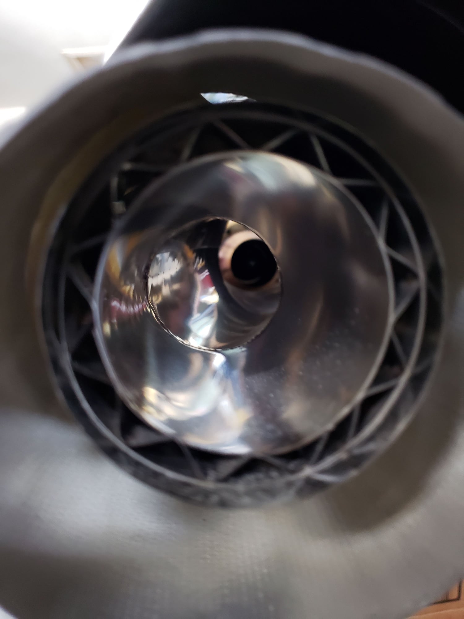
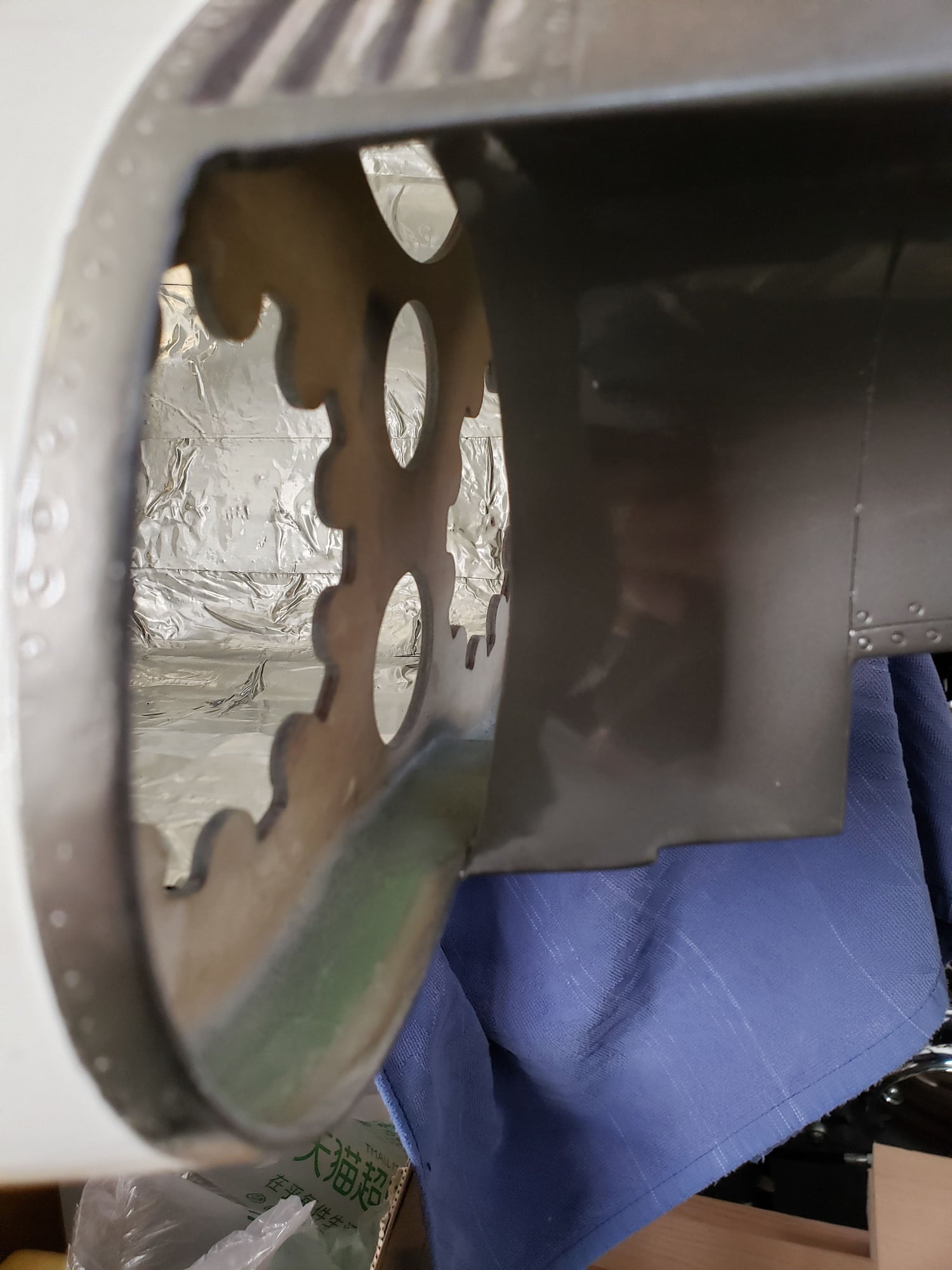
Trying to get the turbine and pipe alignment correct. One thing I noticed is the rear former is about 7/8" inside the fuselage. It looks like it should be further back from what I have seen in pics. See my attached pic. Should I attempt to remove the former and move it farther aft? Or make standoffs for the exhaust cones to attach too?
Last edited by F16Jeff; 05-15-2019 at 08:18 PM. Reason: Forgot attachment
05-16-2019, 04:30 AM
#1213
My Feedback: (48)
Jeff,
As discussed previously the cones need to be cut down to fit. My rear former is recessed about 1/2 inch. I would not recommend trying to move the former. Shorten the wide end of the cones until they just fit in. Then if they don't look right I'd make standoffs.
As discussed previously the cones need to be cut down to fit. My rear former is recessed about 1/2 inch. I would not recommend trying to move the former. Shorten the wide end of the cones until they just fit in. Then if they don't look right I'd make standoffs.
05-16-2019, 06:10 PM
#1215
My Feedback: (11)
Hi Joe or Bob,
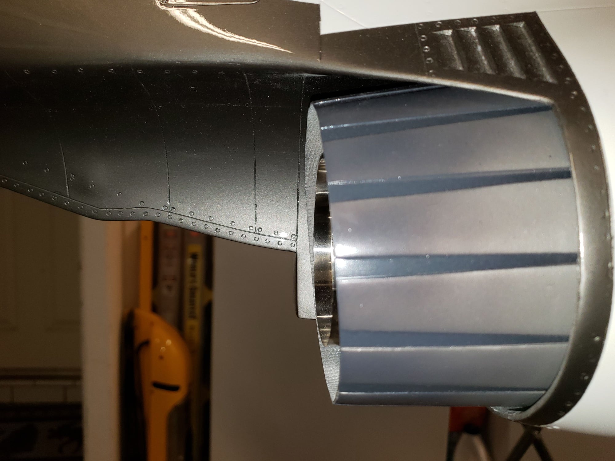
I installed my pipe the way Skymaster suggests and there is almost no down thrust. See pic.
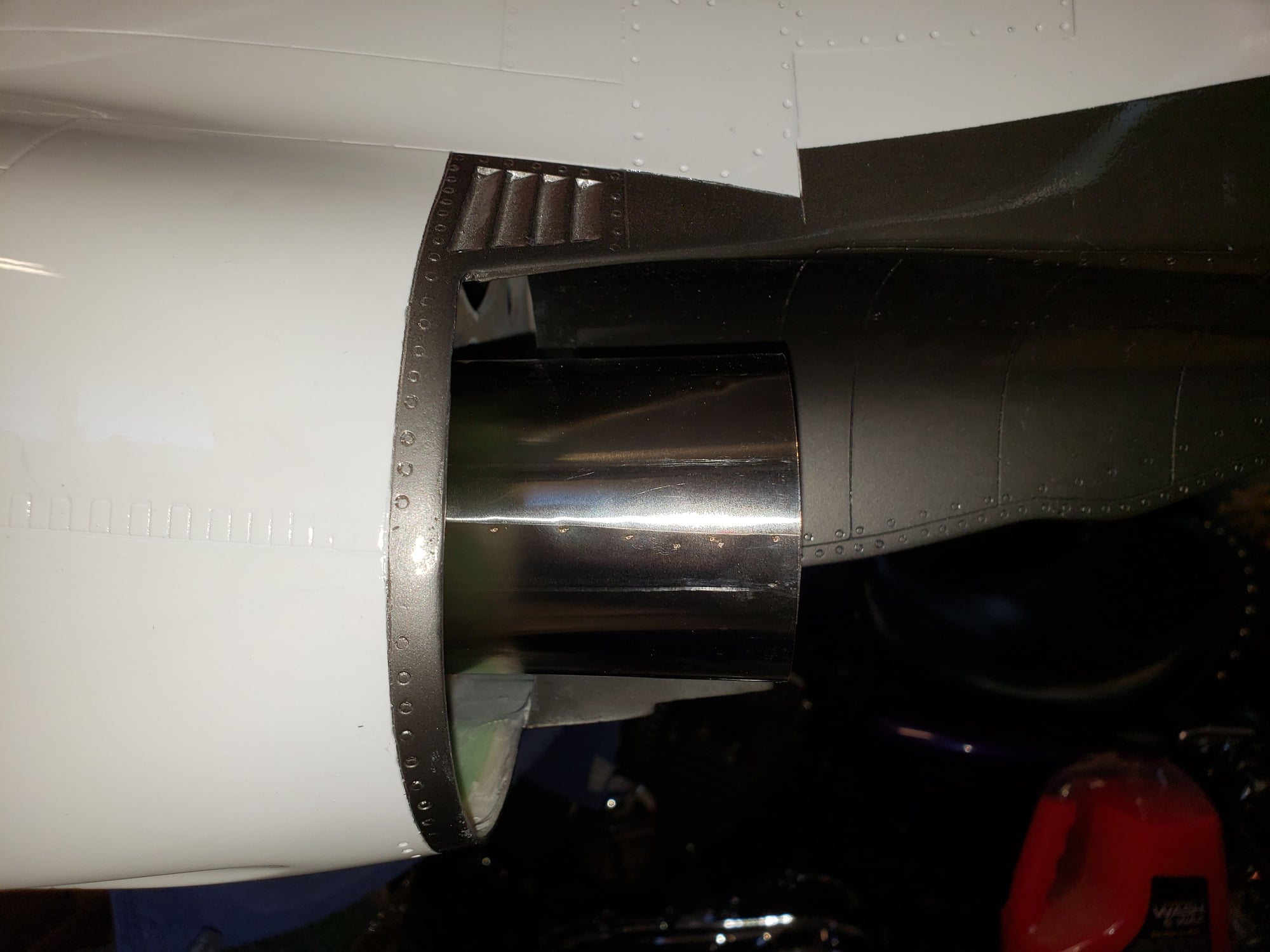
Pipe installed as suggested by Skymaster.
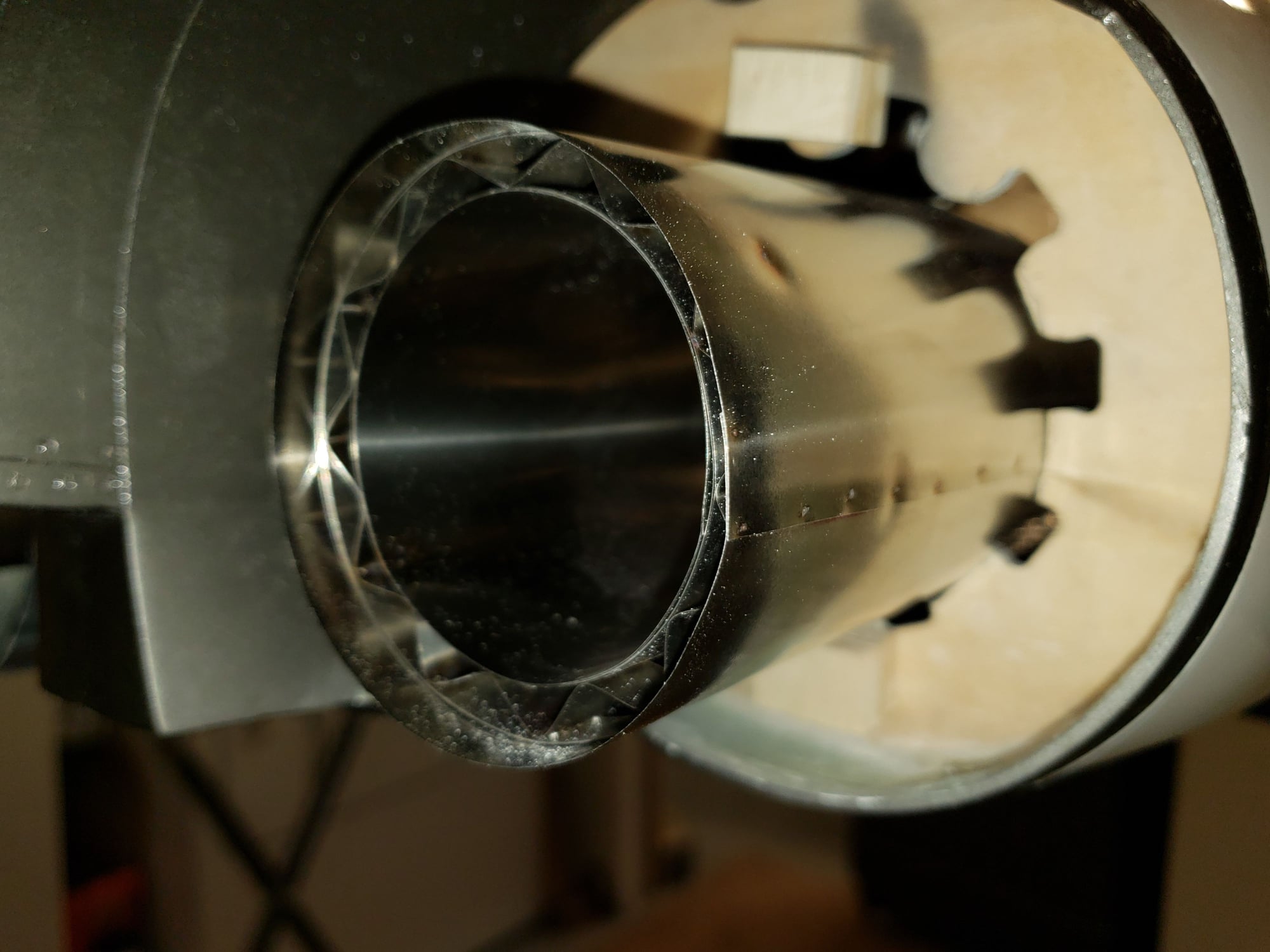
The next pic is with pipe installed inverted. There is lots of down thrust.
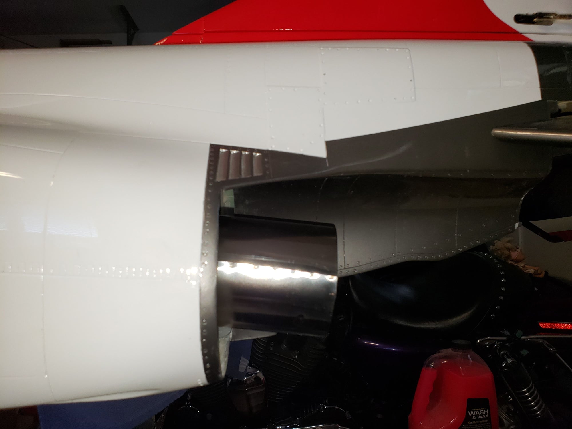
My question is should I go with lots of down thrust or modify the rear former and go between the two angles the pics show?
Thank you,
Jeff
I installed my pipe the way Skymaster suggests and there is almost no down thrust. See pic.
Pipe installed as suggested by Skymaster.
The next pic is with pipe installed inverted. There is lots of down thrust.
My question is should I go with lots of down thrust or modify the rear former and go between the two angles the pics show?
Thank you,
Jeff
05-17-2019, 06:01 AM
#1216
My Feedback: (11)
Hi All,
I decided to install the exhaust the way Skymaster suggested. Trimmed the tabs on the formers for more down thrust. It lowered the pipe about a 1/4 to 3/8 inch. I have the ability to lower more. What are your thoughts on removing lower former tabs entirely?
Thank you,
Jeff

I decided to install the exhaust the way Skymaster suggested. Trimmed the tabs on the formers for more down thrust. It lowered the pipe about a 1/4 to 3/8 inch. I have the ability to lower more. What are your thoughts on removing lower former tabs entirely?
Thank you,
Jeff
05-17-2019, 06:09 AM
#1217
Jeff,
I had my pipe installed the way Skymaster suggested, and I did not lower it on the back. I had a little paint bubbling on the inner underside of the stab and on the aft fuselage cover, but it was not structural, and I repainted it with BVM Heat Shield and then color and that seems to have taken care of it...
Bob

 05-20-2019, 05:34 AM
#1222
My Feedback: (11)
Hi Folks,
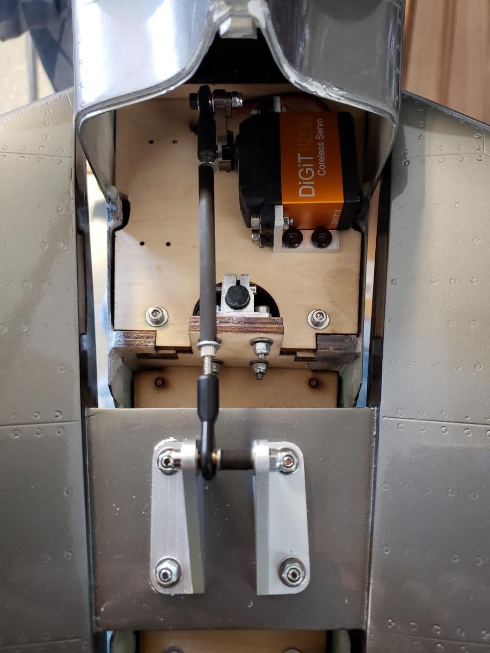
I am now working to finish my aileron and flap servo mountings. Last night I decided to use #4 x 1/2" button head screws since there is minimal room for the screw head under the hatch cover. This turned out to be a bad idea since button head screws strip out very easily. Now I am going to drill out the screws and replace the wood mount pieces.
Is there a better way to mount the servos?
I was thinking of mounting hardwood blocks to the hatch covers and then mount the servos to them. This would make servo arm adjustments easier, plus eliminate the use of the aluminum brackets.
What are your thoughts?
Thank you,
Jeff
05-20-2019, 10:44 AM
#1223
My Feedback: (48)
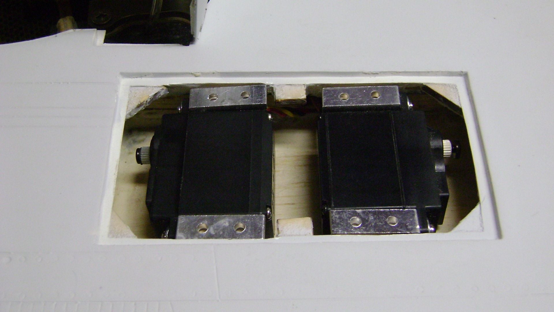
There are several ways you could do it. I made plywood blocks that tie the upper and lower wing skins together. Servos are mounted to the aluminum mounts then screwed into the plywood. I used flat head wood screws counter sunk into the aluminum so they are flush (not shown). If you mount servos to the covers you should reinforce the covers with thin plywood, then run a screw into the block from the outside.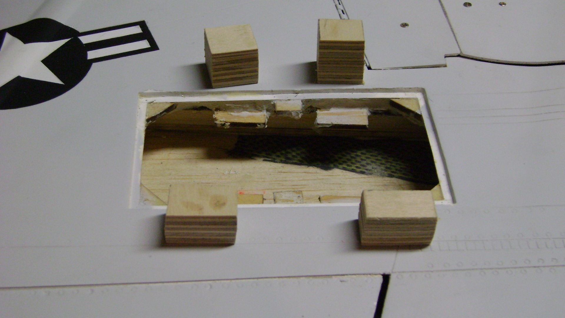
05-20-2019, 11:43 AM
#1224
My Feedback: (11)
Hi Joe,
Thank you for the tips. I will pick up some wood screw and counter sink as well. Going to probably replace the attached plates with new ones and then add the blocks like you have done. It is more work, but I want it done correctly.
Thank you again.
Jeff
Thank you for the tips. I will pick up some wood screw and counter sink as well. Going to probably replace the attached plates with new ones and then add the blocks like you have done. It is more work, but I want it done correctly.
Thank you again.
Jeff