


UP4/UP2 plumbing diagram?
 04-18-2012, 11:05 PM
#1
Im hoping I didnt decide to bite more than I can chew because Im going to re plumb my entire YA F15. It uses a UP2/UP4 combo.....Gear down rear main doors stay down 2 front mains doors close and front nose gear door closes...gear up nose door opens front main doors open gear up and obviously all close. Does anyone have a diagram of some sort describing a little more clearly than UPs diagram how to accomplish something like this? Any general tips before I try to tackle this? The two jet guys in my area are unable to help me right now so im on my own, I figure theres no better way to learn than just doing it.
 04-19-2012, 05:39 AM
#2

My Feedback: (24)

Join Date: Dec 2001
Location: Daytona Beach
Posts: 6,102
Likes: 0
Received 0 Likes
on
0 Posts
Not really sure how much easier it can be explained over what is provided with the valves. Just follow the connections as indicated connecting doors you wished closed gear down to the UP2, doors you wish to remain open gear down to the UP4; it is a fairly simple setup....


 04-19-2012, 07:15 AM
#4
Join Date: Mar 2006
Location: Medford,
NJ
Posts: 228
Likes: 0
Received 0 Likes
on
0 Posts
It may help to set the system up out side the plane using two air cylinders or a gear and an air cylinder. This way you have easy access to the valves and you can understand the tubing locations before snaking long runs. You can get the timing pretty close between the gear and the doors and when you install it you will be pretty close
Scott
Scott
04-19-2012, 09:45 AM
#5

I was going to use this same setup on my f15 but I hate to buy something like this just for the gear doors. My gear will be electric, but I have yet to find something that's as simple as this. I will just have to plug up the gear up and down holes.
04-19-2012, 10:58 AM
#6
Thanks for the help as I study it more the more I seem to get it. I was over thinking it I thought each gear would have its own up and down port but you just have one up and one down port for all three you obviously just tee them off to each gear strut.
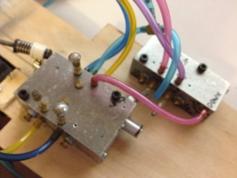
However what I dont understand is the previous builder seemed to block off some ports on the UP4 and UP2 that are not labeled (see photo) why is that? Also any advice on color coding? maybe all gear down side one color up side another color? same for the doors?
However what I dont understand is the previous builder seemed to block off some ports on the UP4 and UP2 that are not labeled (see photo) why is that? Also any advice on color coding? maybe all gear down side one color up side another color? same for the doors?
04-19-2012, 11:20 AM
#7
My Feedback: (24)
Join Date: Dec 2001
Location: Daytona Beach
Posts: 6,102
Likes: 0
Received 0 Likes
on
0 Posts
Both the UP2 and UP4 have 2 sets of outputs for gear up/down and door open/close. one on the side of the valve, one on the top. Looks like the previous owner plugged off one set of the outputs...for example, You could use one output for main retracts the other for the nose; helps distribute the air a bit more evenly with less restriction.
04-19-2012, 03:49 PM
#9

I've had very good luck with the UP valves. The setup you describe UP2/4 I've used on a few models.
Here's a quick sketch in case it's helpful. The suggestion to set it up on the bench first is a good one. Even if you don't use the actual rams and retracts from your model, just use some other ones you may have to simulate them just so you get the plumbing right. Label everything to your understanding then transfer into the model.
During the build of my F-104 I made a quick clip of the doors functioning. The speeds haven't been adjust at this point, it's just installed with the factory settings.
http://www.youtube.com/watch?v=y_tK9DpD9so
