


ORION - sports jet build thread
 07-19-2012, 08:29 AM
#1

Thread Starter
Join Date: Jan 2007
Location: farnborough, , UNITED KINGDOM
Posts: 3,294
Likes: 0
Received 1 Like
on
1 Post
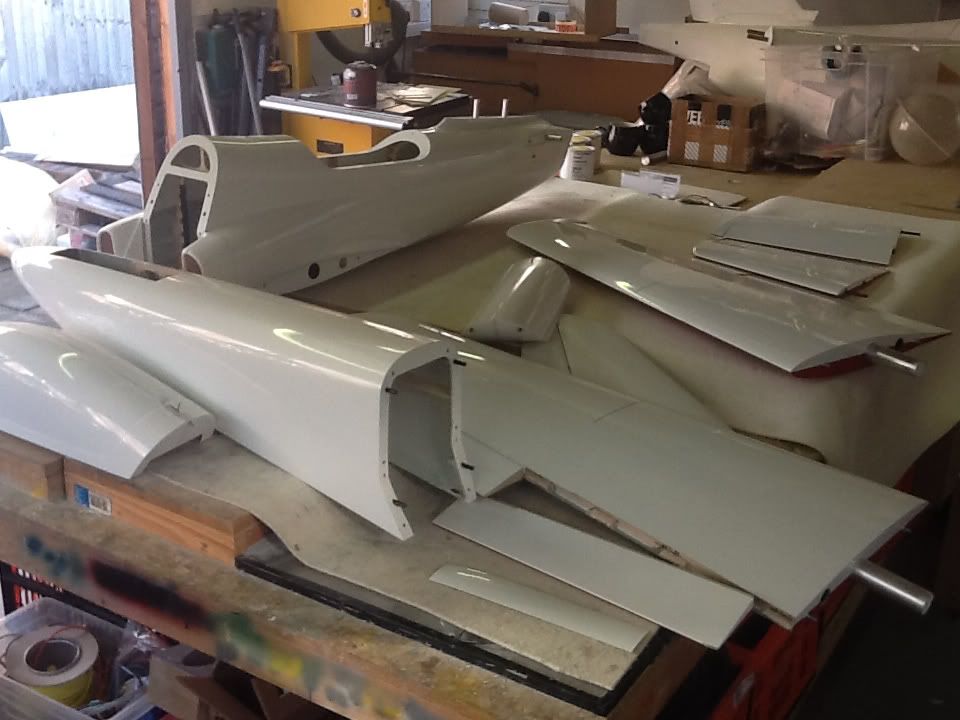
The ORION is a new sports jet design, a 2M span full composite jet airframe with a turbine range of P70-P140.
The construction is vacuum formed glassfibre, with standard layup in the fuselage and with the addition of airex/glass sandwich in wings, stabs and fin/rudder (which are detachable)
Wings are two piece and a nice feature is the fuselage also breaks into two, so those with small vehicles will still be able to transport this jet with ease.
Internally there is a good spread of plywood formers (all hand made by the kit manufacturer) most of which are pre-fitted. All the rear section formers are fitted, including the turbine rails, I adjusted these with plates to cater for the mounting straps for my turbine choice - a B100F from BF Turbines.
Ducting is pre-fitted and between the ducting sits a supplied 2.5L composite fuel tank. As I am using a 120N turbine I am experimenting with making a new slightly larger tank, around 3.1L in capacity which with a small former modification will sit in exactly the same location but provide the extra fuel that I may need.
The nose section requires the nose gear door to be cut out, and once done a set of supplied formers are fitted via the opening to create the nose gear mounting point.
Ailerons and elevators are 'live' hinged at the centre line, flaps are pre-hinged but the supplied hinges are not glued in allowing for linkage and horn fixing before fianl fixing is done. Rudder is similar, pre-hinged but the robart hinge points supplied are not glued in, this is left to the builder to complete.
Finish is currently a painted in the mould, which is to a very high standard, options on colour schemes will be possible as well as customers 'own' designs - information of pricing for this will be available in a few weeks time.
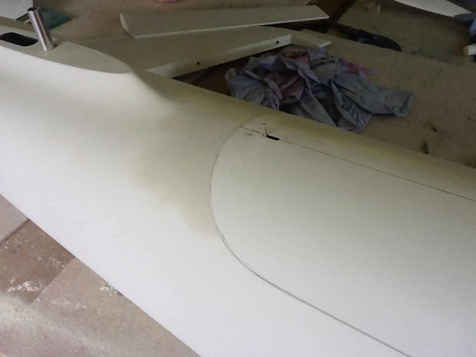
Wing tubes are aluminium and are pre-fitted to the wings, wing tubes are pre-fitted to the fuselage at the correct incidence, one nice touch to the wing/fuselage joint is the intake bulges 'overhang' the mating location so when th wings are slotted in they are covered at the join
Stab and fin are mounted using aluminium tubes, pre-fitted to the stabs and the rear fuselage (for the fin).
More info as the build progresses............
marcs
The construction is vacuum formed glassfibre, with standard layup in the fuselage and with the addition of airex/glass sandwich in wings, stabs and fin/rudder (which are detachable)
Wings are two piece and a nice feature is the fuselage also breaks into two, so those with small vehicles will still be able to transport this jet with ease.
Internally there is a good spread of plywood formers (all hand made by the kit manufacturer) most of which are pre-fitted. All the rear section formers are fitted, including the turbine rails, I adjusted these with plates to cater for the mounting straps for my turbine choice - a B100F from BF Turbines.
Ducting is pre-fitted and between the ducting sits a supplied 2.5L composite fuel tank. As I am using a 120N turbine I am experimenting with making a new slightly larger tank, around 3.1L in capacity which with a small former modification will sit in exactly the same location but provide the extra fuel that I may need.
The nose section requires the nose gear door to be cut out, and once done a set of supplied formers are fitted via the opening to create the nose gear mounting point.
Ailerons and elevators are 'live' hinged at the centre line, flaps are pre-hinged but the supplied hinges are not glued in allowing for linkage and horn fixing before fianl fixing is done. Rudder is similar, pre-hinged but the robart hinge points supplied are not glued in, this is left to the builder to complete.
Finish is currently a painted in the mould, which is to a very high standard, options on colour schemes will be possible as well as customers 'own' designs - information of pricing for this will be available in a few weeks time.
Wing tubes are aluminium and are pre-fitted to the wings, wing tubes are pre-fitted to the fuselage at the correct incidence, one nice touch to the wing/fuselage joint is the intake bulges 'overhang' the mating location so when th wings are slotted in they are covered at the join
Stab and fin are mounted using aluminium tubes, pre-fitted to the stabs and the rear fuselage (for the fin).
More info as the build progresses............
marcs

 07-19-2012, 11:40 AM
#7
Thread Starter
Join Date: Jan 2007
Location: farnborough, , UNITED KINGDOM
Posts: 3,294
Likes: 0
Received 1 Like
on
1 Post
First off was the mod to the formers to allow a larger tank, in the picture the nearest former is as supplied, the rear former has been modified and the lower section has been extended downwards to finish in line with the front former, I added a ply doubler to this former as the lower section which I cut away had lightning holes so was not ideal as a base on which to rest the tank.
Added some tabs to the turbine rails to allow the B100F mounts to fit properly.
marcs
Added some tabs to the turbine rails to allow the B100F mounts to fit properly.
marcs
07-20-2012, 12:22 AM
#9
Thread Starter
Join Date: Jan 2007
Location: farnborough, , UNITED KINGDOM
Posts: 3,294
Likes: 0
Received 1 Like
on
1 Post
Few hours on it this morning before work.
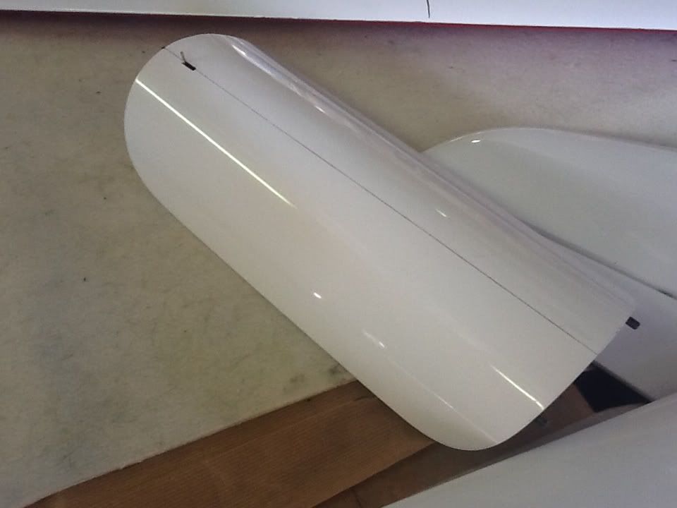
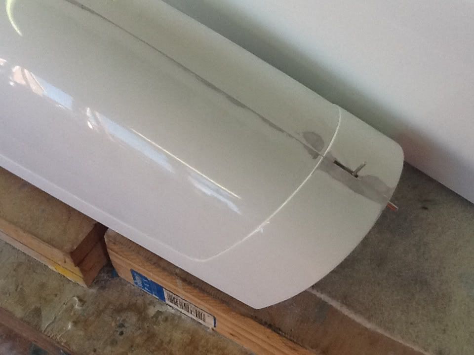
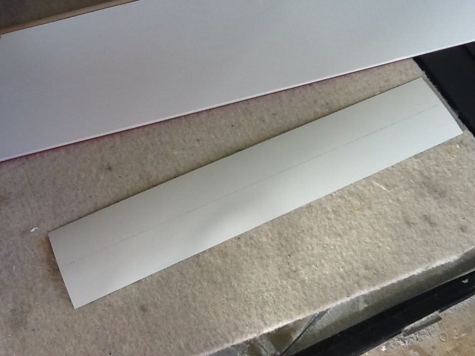
I made a template the other day for the new tank and using a hot wire cutter shaped the basic tank shape, then sanded carefully to achieve the final form with nice radiused corners so the glass cloth will conform and not lift. I have applied four layers of PVA to the foam, its a thin spray version hence the number of layers. Once the foam is dissolved out the PVA will then be flushed out with warm water.
The tank shape has gained around 17mm in depth but as you can see from the pictures the back is now curved, this sits between the ducting when the two meet and provides a good volume gain - its also close to to the CG which is always good. Have added a holding rod which enters the front where the filler will be and now its just a task of glassing it [ ]
]
Before I cut the nose gear door opening, a job I always worry over, I made a mould from the nose door area from glassfibre just in case I needed to make another door following a mistake when cutting out, fortunately it was not needed but in time it might see some action
I masked the area to be cut, taped a plastic straight edge to the edge of the masking tape and used a cut down junior hack saw blade to 'cut' the fuselage, finishing off with a fine toothed saw. It takes time but the end result is a door and opening that have a very small even gap all round.
The nose formers which can now be added are made up from two sections, a two piece nose set and a seven piece gear mounting set.
The nose two piece set are a simple fit, and required no trimming or adjusting. I joined the two using some triangular balsa stock and cyano, this just holds the plate on the former whilst the lugs provide the strength, then I dropped the assembled unit into the fuselage and added aeropoxy around the edge of the plate and pushed the assembly into the nose. I wedged a stick of balsa against it and the already fitted main former to provide some forward pressure and added a bead of aeropoxy around the former and left to dry.
The gear rails are made from three pieces, a main rail, a double for the main rail and a vertical web former. I glued the doublers to the main rail formers with aeropoxy last night and these were dry this morning to assemble. I added the vertical web formers using the triangular balsa method. I found a few adjustments needed to get the whole assembly to fit nice without pressure points on the fuselage but this only took an hour or so to get the whole job done. Once in I went round the whole assembly and bonded with aeropoxy.
marcs
I made a template the other day for the new tank and using a hot wire cutter shaped the basic tank shape, then sanded carefully to achieve the final form with nice radiused corners so the glass cloth will conform and not lift. I have applied four layers of PVA to the foam, its a thin spray version hence the number of layers. Once the foam is dissolved out the PVA will then be flushed out with warm water.
The tank shape has gained around 17mm in depth but as you can see from the pictures the back is now curved, this sits between the ducting when the two meet and provides a good volume gain - its also close to to the CG which is always good. Have added a holding rod which enters the front where the filler will be and now its just a task of glassing it [
]Before I cut the nose gear door opening, a job I always worry over, I made a mould from the nose door area from glassfibre just in case I needed to make another door following a mistake when cutting out, fortunately it was not needed but in time it might see some action
I masked the area to be cut, taped a plastic straight edge to the edge of the masking tape and used a cut down junior hack saw blade to 'cut' the fuselage, finishing off with a fine toothed saw. It takes time but the end result is a door and opening that have a very small even gap all round.
The nose formers which can now be added are made up from two sections, a two piece nose set and a seven piece gear mounting set.
The nose two piece set are a simple fit, and required no trimming or adjusting. I joined the two using some triangular balsa stock and cyano, this just holds the plate on the former whilst the lugs provide the strength, then I dropped the assembled unit into the fuselage and added aeropoxy around the edge of the plate and pushed the assembly into the nose. I wedged a stick of balsa against it and the already fitted main former to provide some forward pressure and added a bead of aeropoxy around the former and left to dry.
The gear rails are made from three pieces, a main rail, a double for the main rail and a vertical web former. I glued the doublers to the main rail formers with aeropoxy last night and these were dry this morning to assemble. I added the vertical web formers using the triangular balsa method. I found a few adjustments needed to get the whole assembly to fit nice without pressure points on the fuselage but this only took an hour or so to get the whole job done. Once in I went round the whole assembly and bonded with aeropoxy.
marcs
07-21-2012, 01:25 AM
#10
Thread Starter
Join Date: Jan 2007
Location: farnborough, , UNITED KINGDOM
Posts: 3,294
Likes: 0
Received 1 Like
on
1 Post
Nose gear installation can now be done...
The gear I am using is Electron 40 series, these are electric, superbly made and having used the 50 series on another jet have found them to be 100% reliable. The Orion is a slightly smaller jet so I went for 40's instead of the 50's.
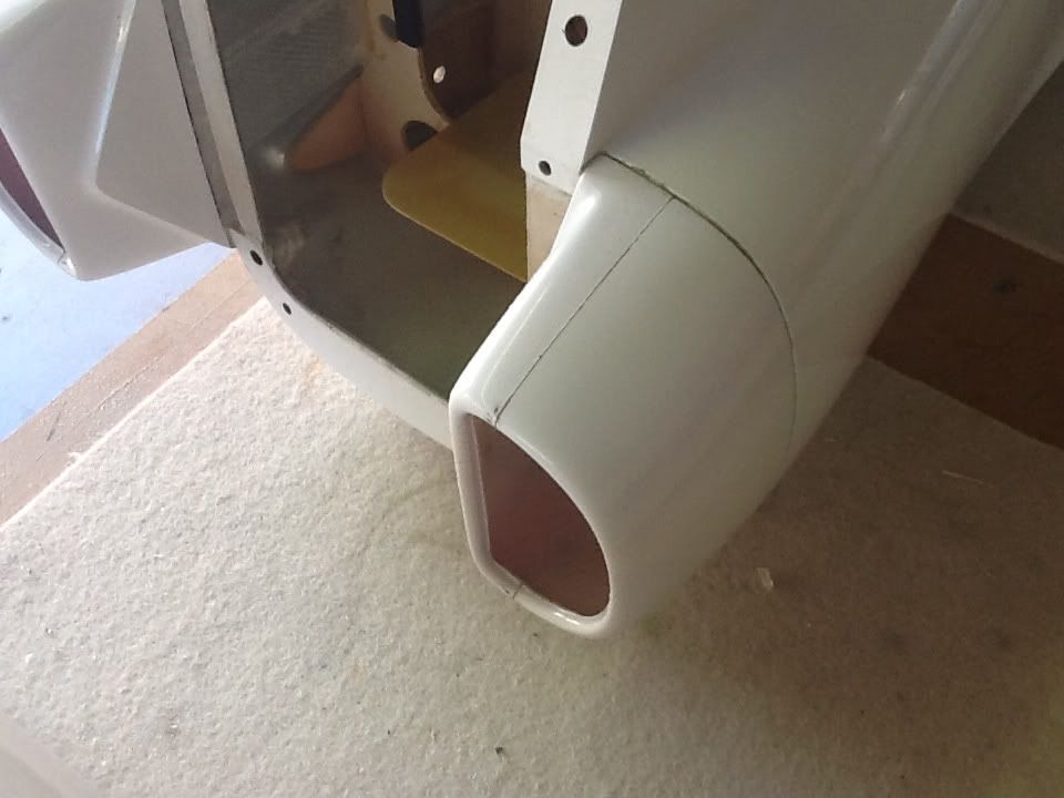
The nose retract has an optional direct steering tiller option, this I used on the other jet and found it bang on, the tiller simply links up with a servo and using equal arms lengths at the same distance from centres of the servo arm to match the tiller hole spacing you have a rock solid steering set up. I plan to add a servo in the lower area of the nose section just behind where the tiller sits aft of the bulkhead former (see pic)
A little sanding to get the retract unit to fit, but nothing major. Drilled and aligned the retract. I opted to use M4 blind nuts as these make for easier maintenance and saves hassle trying to get to nuts and washers on the underside of the mounting rails. I use a neat brass insert type blind nut, it requires a 5.5mm hole for fitting and I find them much easier to use when compared to the types with a flange and barbs plus they require less room.
Not sure how the levels are going to be as yet but I hope to be able to adjust ride heights once the mains are in. One slight 'issue' is the nose wheel sits just proud of the gear door opening, as its forward retracting the slope of the nose makes space more restricted, its not a lot but will need to mod the door slightly to get a closure fit, I have two current thoughts, first to cut an opening in the nose door a little bigger all round than the wheel shape and fill this with a wire mesh which I can shape into a slight dome, it should appear as a vent once done and painted, or my second choice is to cut down a wheel spat I have in my spares box and glue this to the door to give a 'bump' look to the door to give the required clearance.
Gear is all Jet-A1 who provide a great service and nice people to do business with
marcs
The gear I am using is Electron 40 series, these are electric, superbly made and having used the 50 series on another jet have found them to be 100% reliable. The Orion is a slightly smaller jet so I went for 40's instead of the 50's.
The nose retract has an optional direct steering tiller option, this I used on the other jet and found it bang on, the tiller simply links up with a servo and using equal arms lengths at the same distance from centres of the servo arm to match the tiller hole spacing you have a rock solid steering set up. I plan to add a servo in the lower area of the nose section just behind where the tiller sits aft of the bulkhead former (see pic)
A little sanding to get the retract unit to fit, but nothing major. Drilled and aligned the retract. I opted to use M4 blind nuts as these make for easier maintenance and saves hassle trying to get to nuts and washers on the underside of the mounting rails. I use a neat brass insert type blind nut, it requires a 5.5mm hole for fitting and I find them much easier to use when compared to the types with a flange and barbs plus they require less room.
Not sure how the levels are going to be as yet but I hope to be able to adjust ride heights once the mains are in. One slight 'issue' is the nose wheel sits just proud of the gear door opening, as its forward retracting the slope of the nose makes space more restricted, its not a lot but will need to mod the door slightly to get a closure fit, I have two current thoughts, first to cut an opening in the nose door a little bigger all round than the wheel shape and fill this with a wire mesh which I can shape into a slight dome, it should appear as a vent once done and painted, or my second choice is to cut down a wheel spat I have in my spares box and glue this to the door to give a 'bump' look to the door to give the required clearance.
Gear is all Jet-A1 who provide a great service and nice people to do business with
marcs
07-21-2012, 01:35 PM
#11
Lovely model!
Does the nosewheel hit on the top side of the fuselage when retracted?
If not you could fit a couple of tapered plywood spacers (from say 2mm thick
tapered down to 1mm thick) to tilt the whole retract body up at the front.
You don't need much taper, a little angle at the retract = quite a large difference
out at the end of the leg.
Electric retracts, electric brakes? Any more news on these? - John.
One slight 'issue' is the nose wheel sits just proud of the gear door opening, as its forward retracting the slope of the nose makes space more restricted,
If not you could fit a couple of tapered plywood spacers (from say 2mm thick
tapered down to 1mm thick) to tilt the whole retract body up at the front.
You don't need much taper, a little angle at the retract = quite a large difference
out at the end of the leg.
Electric retracts, electric brakes? Any more news on these? - John.
07-22-2012, 12:43 AM
#12
Thread Starter
Join Date: Jan 2007
Location: farnborough, , UNITED KINGDOM
Posts: 3,294
Likes: 0
Received 1 Like
on
1 Post
John, there is plenty of room under the nosewheel so a tapered shim could fix this, and might try it cheers.
Should have our new elelctric brakes at Jetpower
marcs
Should have our new elelctric brakes at Jetpower
marcs
07-23-2012, 08:01 AM
#13
Thread Starter
Join Date: Jan 2007
Location: farnborough, , UNITED KINGDOM
Posts: 3,294
Likes: 0
Received 1 Like
on
1 Post
Turbine seated in its mount and have trimmed the ducting to clear the fuel feed lines into the turbine. I have moved the turbine as far forwards as possible, the started motor is a few millimeters from the ducting wall where it joins.
New 3.6L tank is now finished and in pace in its space, its just over 1L larger than the original and occupies almost the same space, albeit some minor surgery to the nose section which I had to remove a piece from to allow it to fit without hitting the tank.
I added a small plate under the tank to spread the load on the tank base, in its standard form the whole tank rests on two 3mm ply formers and I felt this might be a too smaller pressure point for a full 3.6L tank.
Made the nose steering servo mount, a lite ply plate which screws to the existing side rails running down each side of the nose section, I fitted a servo and made up two M2 studding ball links which where adjusted to the right length to mate with the servo and hook up onto the neat steering tiller fitted to the Electron retract unit.
I have also added the main hatch latch and next job is to do the same to the canopy.
I have a few more basic jobs to do then its off to paint, after that the main installation can start.
marcs
07-25-2012, 01:18 AM
#14
Thread Starter
Join Date: Jan 2007
Location: farnborough, , UNITED KINGDOM
Posts: 3,294
Likes: 0
Received 1 Like
on
1 Post
Needed to introduce any required holes in the fuselage before it went to paint tomorrow so next job was to figure out the best way to link the elevators up.
I say best way as there is no real plan for this, the stabs are too thin to get a decent servo in, and did not want to try to place a servo inside the fuselage right at the back, to much tail weight and possibly too close to heat even though the pipe is a Grummania twin walled unit.
Whilst over at a friends workshop who flies helis I spotted a neat looking ball raced crank device, this mounts on the heli's side frame and converts an internal servo linkage to external to drive something at the tail end (not sure what). I looked over the options and worked out if the linkages might work and took the plunge.....
The plan was to mount this 'switchover crank' (my word for it) under the stab and in line with the elevator horn, keeping the linkage as short as possible, where it crosses inside the fuselage I plan to make a pushrod from an arrow shaft (aluminium tube wound in carbon - light and very stiff) which will run from a ball link on the crank back to around the turbine area in the fuselage where a servo )one each side) can be easily mounted and accessible.
The 'switchover crank' has twin bearings, no slop or play, almost totally friction free and hooked up to some good ball links should give a nice linkage set-up with (fingers crossed) no slop.
I added ply plates to the inside of the fuselage around the area the switchover cranks will mount to add stiffness to the mounting and provide a base to install some M3 blind nuts.
marcs
I say best way as there is no real plan for this, the stabs are too thin to get a decent servo in, and did not want to try to place a servo inside the fuselage right at the back, to much tail weight and possibly too close to heat even though the pipe is a Grummania twin walled unit.
Whilst over at a friends workshop who flies helis I spotted a neat looking ball raced crank device, this mounts on the heli's side frame and converts an internal servo linkage to external to drive something at the tail end (not sure what
). I looked over the options and worked out if the linkages might work and took the plunge.....The plan was to mount this 'switchover crank' (my word for it) under the stab and in line with the elevator horn, keeping the linkage as short as possible, where it crosses inside the fuselage I plan to make a pushrod from an arrow shaft (aluminium tube wound in carbon - light and very stiff) which will run from a ball link on the crank back to around the turbine area in the fuselage where a servo )one each side) can be easily mounted and accessible.
The 'switchover crank' has twin bearings, no slop or play, almost totally friction free and hooked up to some good ball links should give a nice linkage set-up with (fingers crossed) no slop.
I added ply plates to the inside of the fuselage around the area the switchover cranks will mount to add stiffness to the mounting and provide a base to install some M3 blind nuts.
marcs
 07-26-2012, 11:42 PM
#16
Thread Starter
Join Date: Jan 2007
Location: farnborough, , UNITED KINGDOM
Posts: 3,294
Likes: 0
Received 1 Like
on
1 Post
The Orion is now with Phil Noel aka Pinnacle Aviation who will post here on the paint process.
Phil as you may remember is the genius who repaired and painted Ali's Futura following its maiden meeting with terra firma and many other superb builds.
The scheme will be a flowing blend of colour sections with a theme taken from an F3A type look as oppose to a 'scale' jet look.
marcs
Phil as you may remember is the genius who repaired and painted Ali's Futura following its maiden meeting with terra firma and many other superb builds.
The scheme will be a flowing blend of colour sections with a theme taken from an F3A type look as oppose to a 'scale' jet look.
marcs
07-29-2012, 12:46 PM
#17


Join Date: Feb 2004
Location: herts, UNITED KINGDOM
Posts: 589
Likes: 0
Received 0 Likes
on
0 Posts
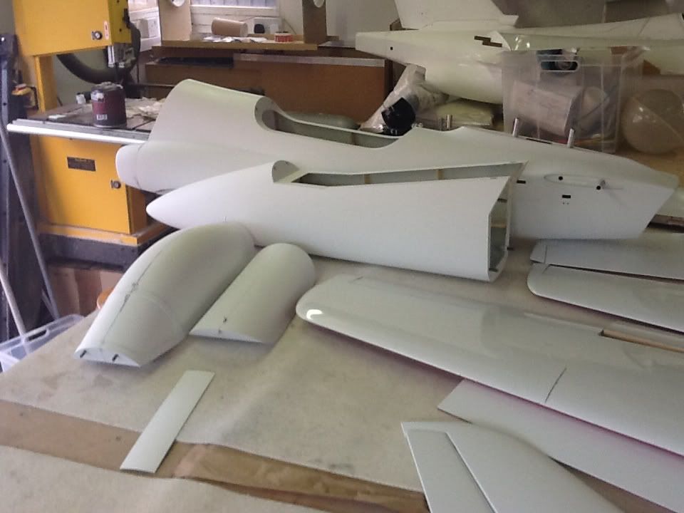
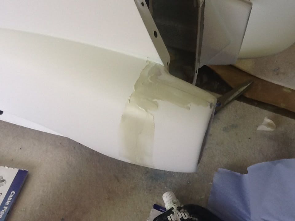
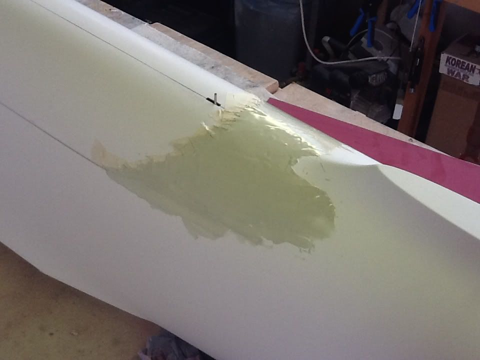
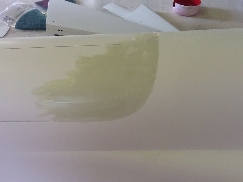
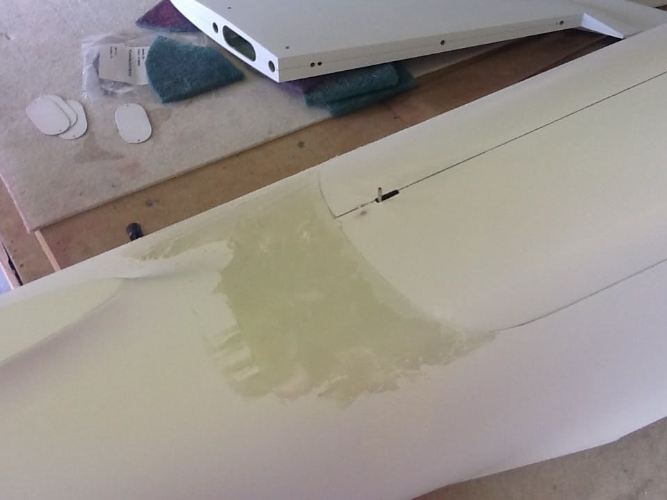
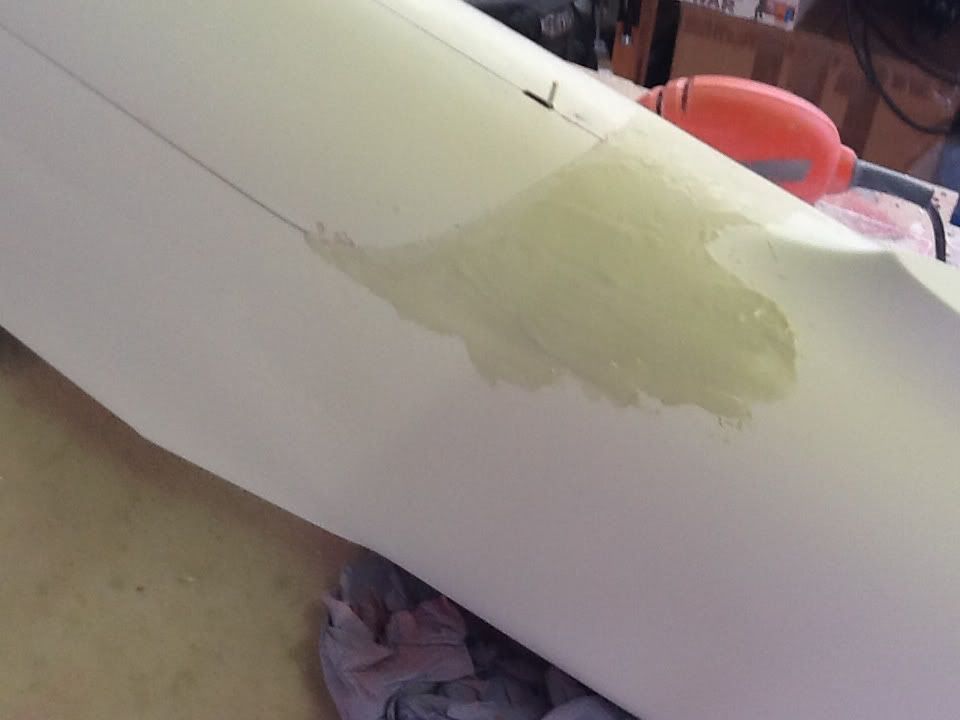
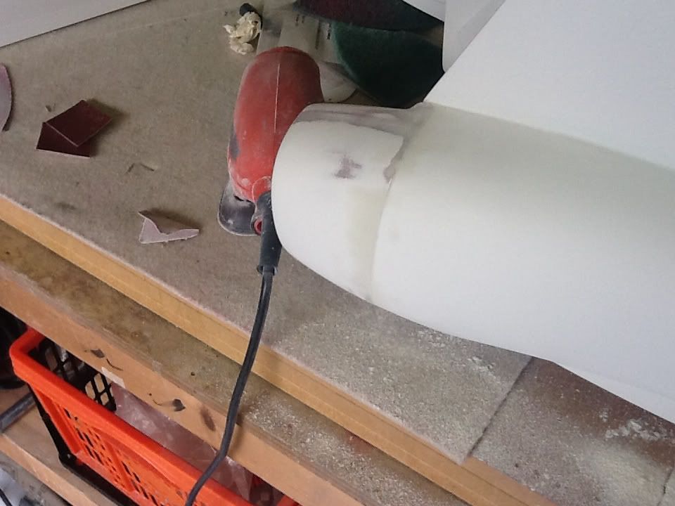
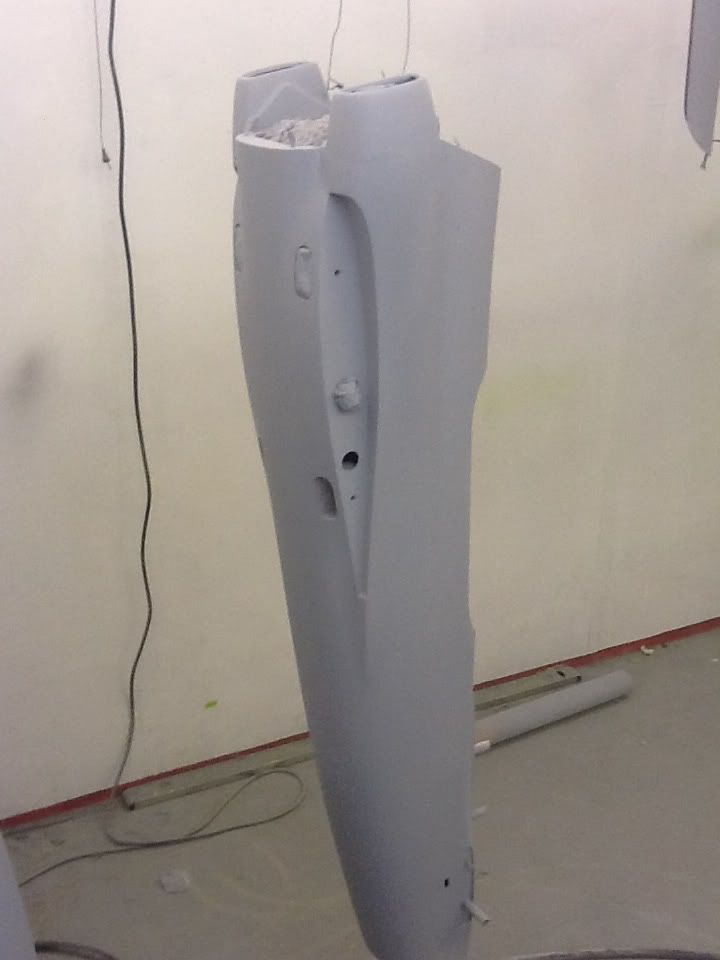
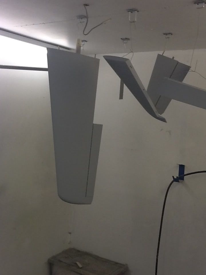
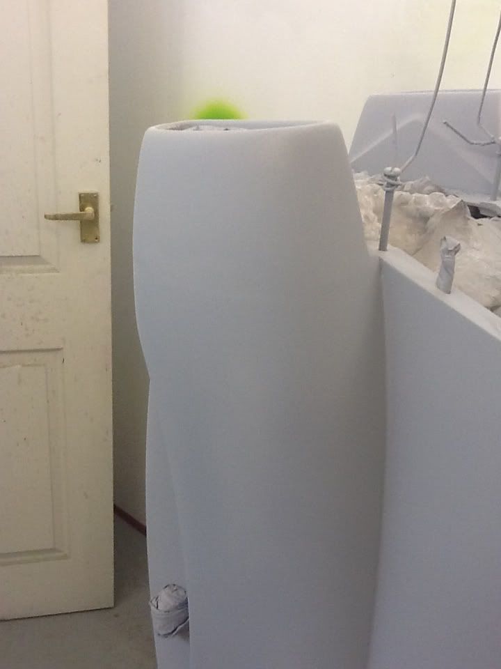
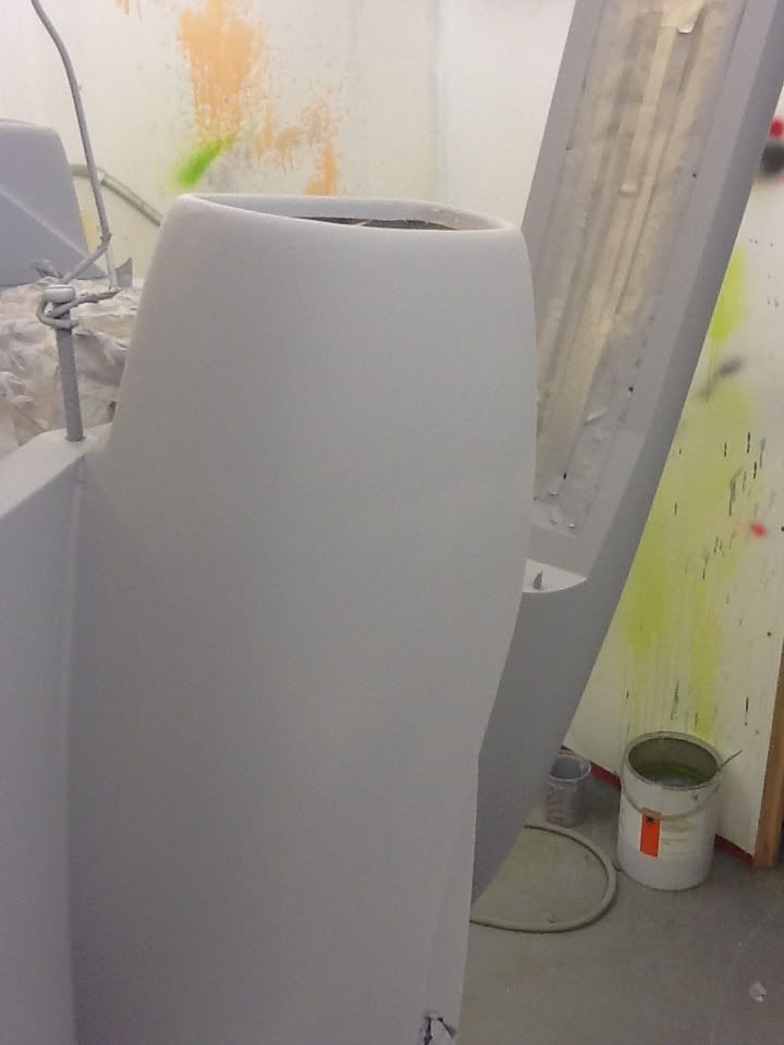
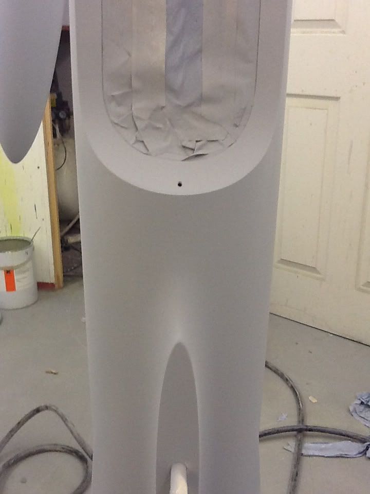
Work started today with preparing the Orion for paint, all the fuse parts are now sanded down with scotchbrite and the seams have been sanded ready for filler. The quality of this model is excellent with only minimal filling. All the seams on the fuse have been pre sanded and filled, it's only the engine hatch, canopy and intake to fuse seams that need some work.
Enjoy the photos, tomorrow I will finish sanding the wings, tailplanes and fins and start filling the the joints.
Enjoy the photos, tomorrow I will finish sanding the wings, tailplanes and fins and start filling the the joints.


 07-30-2012, 12:24 AM
#19
Join Date: Feb 2004
Location: herts, UNITED KINGDOM
Posts: 589
Likes: 0
Received 0 Likes
on
0 Posts
Hi Mark,
I use a number of different fillers for all sorts of jobs.
There are two types of filler i use a lot of first is polystop LP filler made by Sikkens and the other is Dolphin Glaze made bu U-POL, both are two part
i hope this is helpful
I use a number of different fillers for all sorts of jobs.
There are two types of filler i use a lot of first is polystop LP filler made by Sikkens and the other is Dolphin Glaze made bu U-POL, both are two part
i hope this is helpful
07-30-2012, 01:07 PM
#20
Join Date: Feb 2004
Location: herts, UNITED KINGDOM
Posts: 589
Likes: 0
Received 0 Likes
on
0 Posts
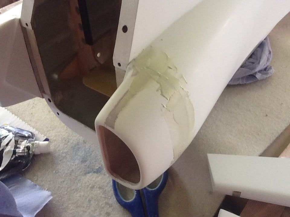
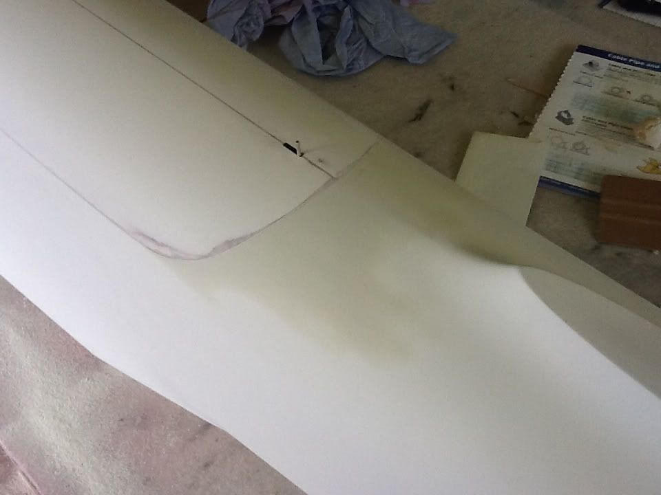
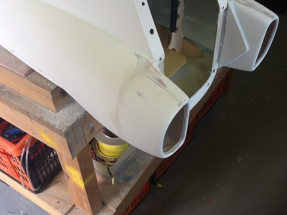
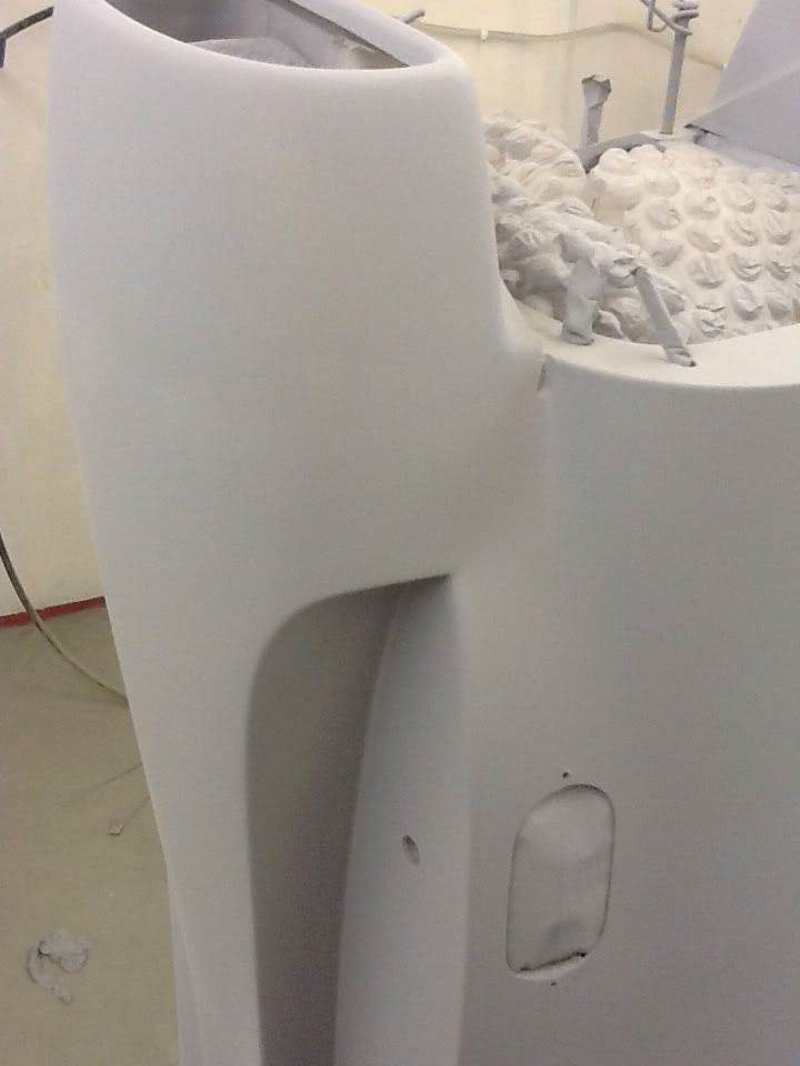
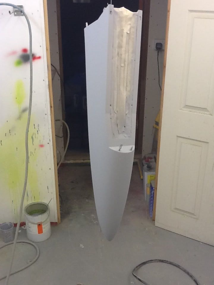
Today I finish preparing the model for priming, I also did all the filling around the intakes plus there was a slight discrepency around the engine hatch which I sorted.


 07-31-2012, 01:09 PM
#21
Join Date: Feb 2004
Location: herts, UNITED KINGDOM
Posts: 589
Likes: 0
Received 0 Likes
on
0 Posts
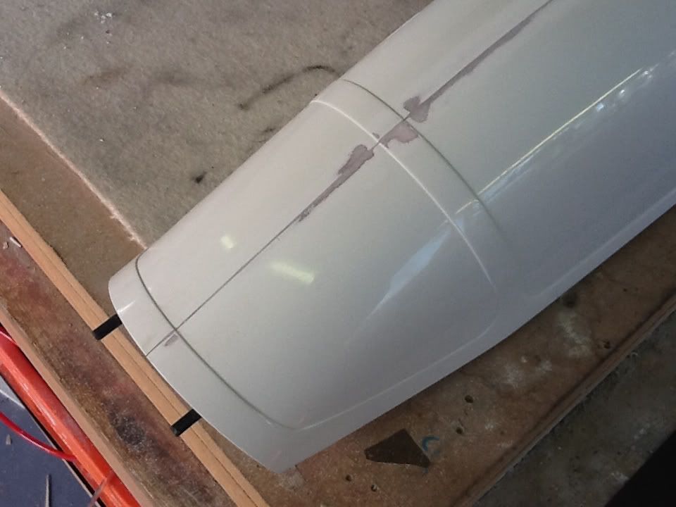
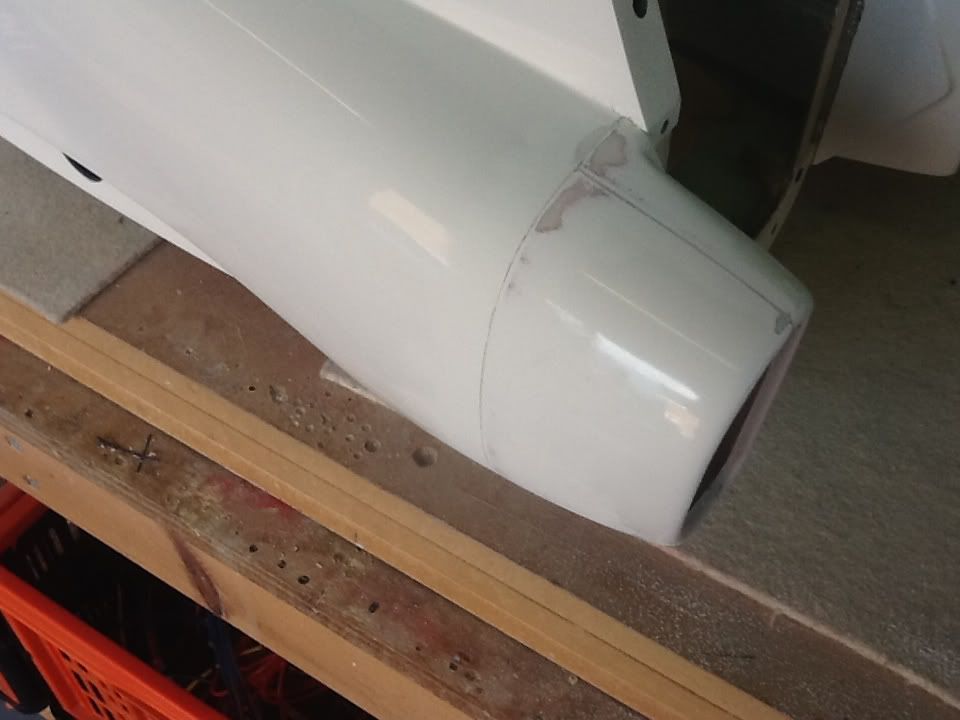
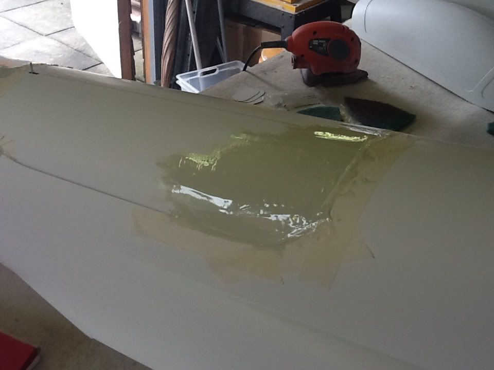
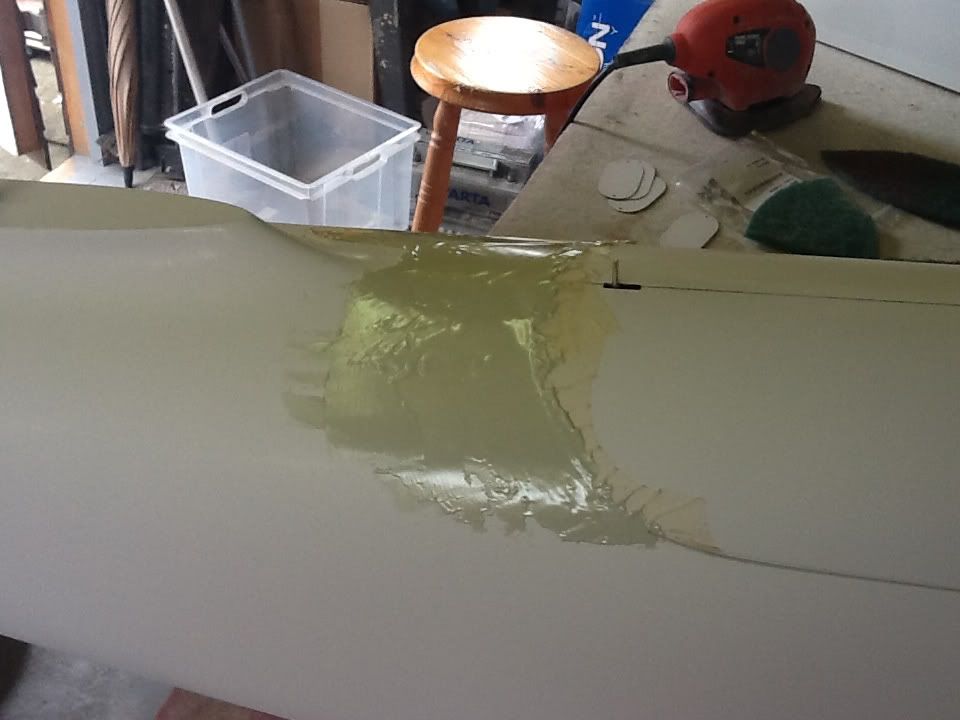
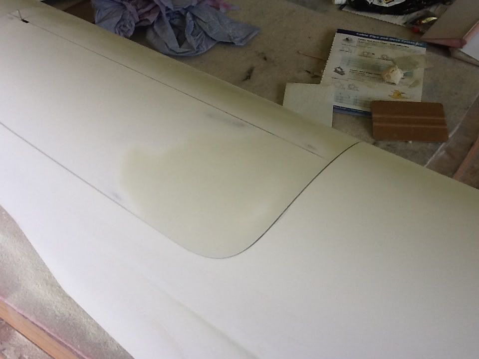
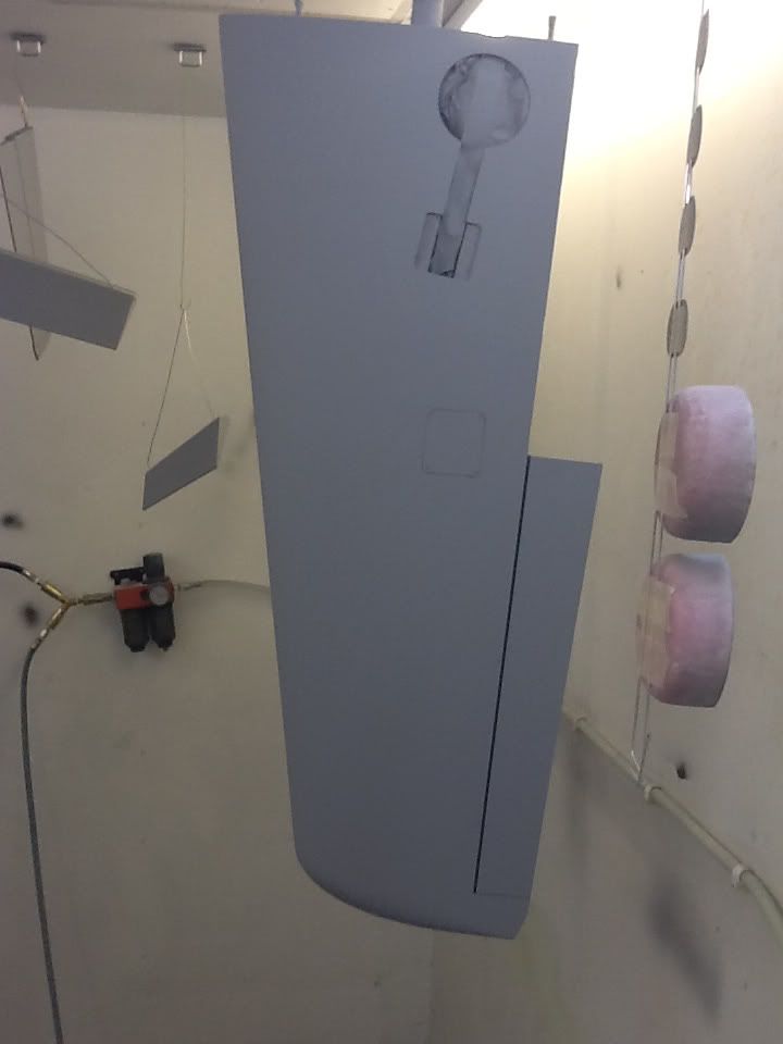
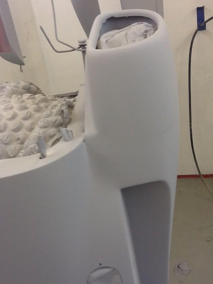
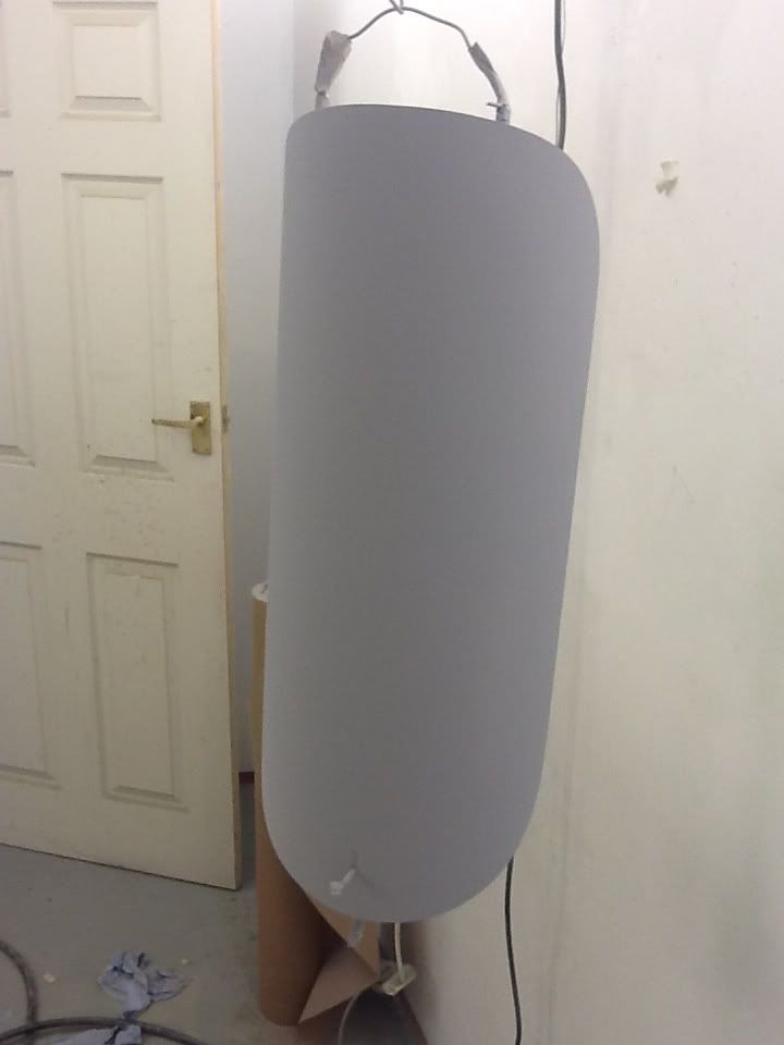
This morning I was able to shoot some primer on the model and to see if I had missed anything, as you will see there is a little area that needs filling by the intake, the rest of the model is looking good and the adjustments by the engine hatch looks ok along with the intake joints.


 08-07-2012, 12:58 PM
#23
Join Date: Feb 2004
Location: herts, UNITED KINGDOM
Posts: 589
Likes: 0
Received 0 Likes
on
0 Posts
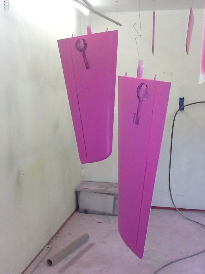
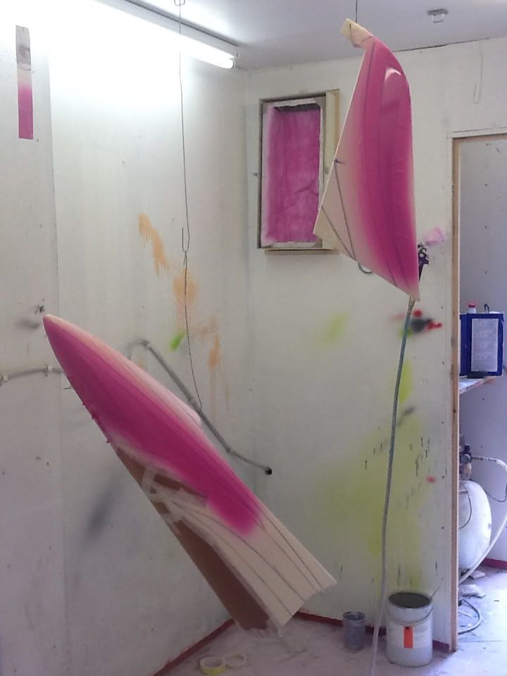
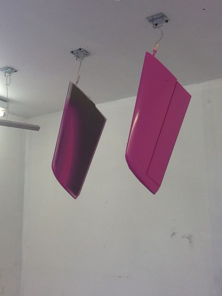
After spending a day masking the model I was able to put the first of six colours that I will be painting on the model.
Pink, turquoise, burgundy, royal Blue, Silver and finally gunmetal grey.
Pink, turquoise, burgundy, royal Blue, Silver and finally gunmetal grey.


