


Fei Bao Euro Fighter EF-2000 build thread *Lots of Pics!*
 11-08-2012, 11:27 AM
#26
Senior Member
Join Date: Jan 2009
Location: au dessus des nuages, FRANCE
Posts: 115
Likes: 0
Received 0 Likes
on
0 Posts
Hi,
I have the same plane with me and I think some of the photos look like the pictures I have my friend Gilles plane?
Regards
Mikaël
I have the same plane with me and I think some of the photos look like the pictures I have my friend Gilles plane?
Regards
Mikaël
 11-08-2012, 05:18 PM
#27

Thread Starter
My Feedback: (1)

Hello mikael.
They look like Gilles plane because he sent me his pics of his setup so you will see a lot of similar elements in my build.
They look like Gilles plane because he sent me his pics of his setup so you will see a lot of similar elements in my build.
11-09-2012, 01:16 AM
#28
Junior Member
Join Date: Oct 2006
Location: Cranves sales, FRANCE
Posts: 17
Likes: 0
Received 0 Likes
on
0 Posts
Hi,
I am Gilles and here is my last setup:
Merlin 160 (17.5 thrust) and Y thrust pipe.
Only 2 tanks, the main tank is the rear one and the second is the big one. The big tank is backware as original FeiBao (or C&C) setup. With this setup no CG problems......
Regards.
Gilles
I am Gilles and here is my last setup:
Merlin 160 (17.5 thrust) and Y thrust pipe.
Only 2 tanks, the main tank is the rear one and the second is the big one. The big tank is backware as original FeiBao (or C&C) setup. With this setup no CG problems......
Regards.
Gilles
11-11-2012, 08:30 AM
#29
Thread Starter
My Feedback: (1)
Next I got the front gear blind nuts installed and gear mounted.
One thing that I found was the Air Cylinder for the front gear interferes with the Intake ducts. I thought I would need to cut them but as long as the intake ducts are in place prior to mounting the front gear it fits....barely.
The air cylinder does put pressure on the intake ducts but it does hold them in place, no cutting was necessary.
The next step was to fab up the gear cover. As previously mentioned, the prior one was destroyed and I did not receive a new one with the replacement fuse.
I thought of a few different ways to make it but I settled on first making it out of thin balsa and covering with a few layer of fiberglass.
11-11-2012, 08:36 AM
#30
Thread Starter
My Feedback: (1)
The servo mount that is above the box I believe should be on the other side of the former. I think this was installed on the wrong side but I'm not sure. I might cut it off or I might use it for the scale parts of the gear to mount to.
Here is pics of the finished balsa box, Finished balsa box in place and finished Glassed box in place. This will be painted when the rest gets painted.
Here is pics of the finished balsa box, Finished balsa box in place and finished Glassed box in place. This will be painted when the rest gets painted.
11-11-2012, 08:40 AM
#31
Thread Starter
My Feedback: (1)
Here is a shot of the front gear door from the old fuse. I don't think It's reusable without a bunch of repairs. Trying to order a new one from GJC.
Next step I think will be mounting new gear doors on the mains and painting.
Stay tuned!
Next step I think will be mounting new gear doors on the mains and painting.
Stay tuned!
11-12-2012, 08:21 AM
#32
Thread Starter
My Feedback: (1)
Well I decided to not work on the gear doors and work on engine and pipe mounting.
Mounted the blind nuts for the Turbine.
Mounted the turbine.
I didn't have much room to play with because the pipe is short. you can see in the last picture that the pipe is 1" away from the end of the outlets. I have read on many threads that this is acceptable. I have read about guys setting it up with 1 3/4" to flush.
In the damaged fuse the turbine was mounted another 1" back so the pipe would have been flush. In Gilles pictures above his turbine is much farther forward. Hopefully this setup works fine with CG. We will go with that and if it needs to get changed later i'll find out when its almost complete!
For side to side spacing of the turbine the orientation of the nuts and mounts made it sit perfectly in between the mounting rails. Easy!
11-12-2012, 08:42 AM
#35
Thread Starter
My Feedback: (1)
Next step was to remove the assembly from the plane and get it lined up.
I took a piece of tape and ran it across the opening of the pipe. Measured the center of the opening. This center point would line up whith the 30mm wood spacer that is inserted between the turbine and pipe. Ignore the line with the squiggles on it. That was the incorrect line.
Once I was satisfied with the location and all I mounted 2 Maple blocks to the rails, ensuring to keep them away from the ends or they would interfere with the aluminum mounting brackets. If you look closely at the second picture you can see a brass leg coming down from the pipe. This lines up with the former that is close to the pipe opening. This brass leg is riveted to the pipe. This allows any final adjustments to be made and allows a firmer mounting of the pipe.
Picture #3 shows the works reinstalled installed, perfectly centered to where it should be on the mark! yahoo. NOTE. Removing the pipe from the rails when installed will be pretty difficult if you try to do it with the screws holding the mounting tabs from the pipe. Reason for this is because the wheel well covers will be in the way. They are not in the way now as they are not installed. My solution is take turbine out. Remove rails and pipe assembly. Slide forward and remove screws holding in maple mounting blocks. This could be done when installed but easier if done the way I suggested.
Cheers.
11-12-2012, 08:44 AM
#36
Thread Starter
My Feedback: (1)
ORIGINAL: looping-74
Hello,
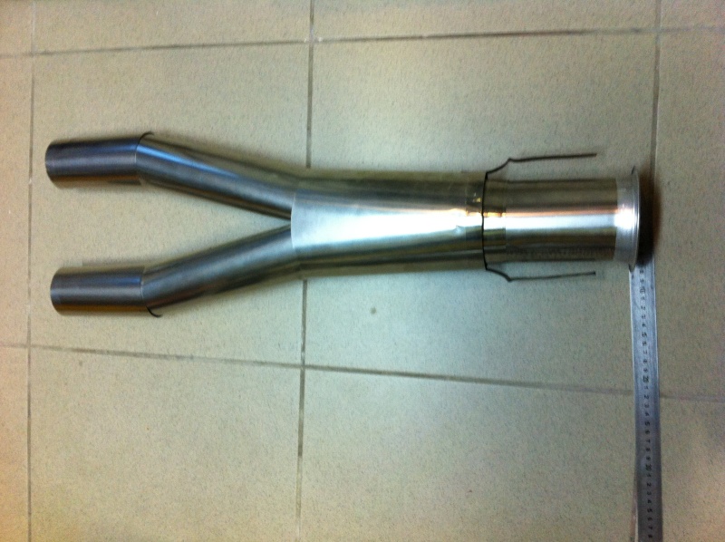
It's easy, i just made an extension for the exaust pipe.
Gilles
Hello,
It's easy, i just made an extension for the exaust pipe.
Gilles
11-12-2012, 08:47 AM
#37
Thread Starter
My Feedback: (1)
Last picture. Yes it's not a straight pipe but it's just for reference.
NOTE. Picture is turned 90 deg as my phone was the wrong way.
Turn your head to the side to view.
NOTE. Picture is turned 90 deg as my phone was the wrong way.
Turn your head to the side to view.
11-12-2012, 08:56 AM
#38
Junior Member
Join Date: Oct 2006
Location: Cranves sales, FRANCE
Posts: 17
Likes: 0
Received 0 Likes
on
0 Posts
Yes it's too difficult to obtain the good CG so i have change my setup...With this setup ,2 LiFE 2500 batteries + 2 Hypérion 2s 2600 lipo for the engine in the nose, i also need 50 gr more lead for a good cg.
11-13-2012, 12:09 PM
#41
Senior Member
Join Date: Jan 2009
Location: au dessus des nuages, FRANCE
Posts: 115
Likes: 0
Received 0 Likes
on
0 Posts
Hi,
Here is the mod that Gilles did for the exhaust nozzles of our EF2000, an extension of 15cm.
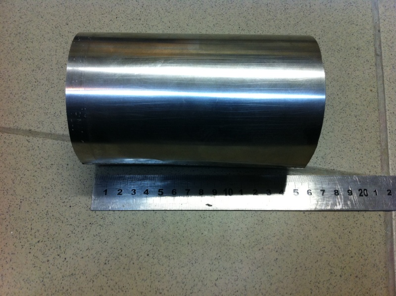
Here is the mod that Gilles did for the exhaust nozzles of our EF2000, an extension of 15cm.
11-14-2012, 05:20 AM
#42
Junior Member
Join Date: Oct 2006
Location: Cranves sales, FRANCE
Posts: 17
Likes: 0
Received 0 Likes
on
0 Posts
Hi,
This extension is adjustable upon request. With this system it's easy to adapt the space between the turbine and the exhaust pipe.
This extension is adjustable upon request. With this system it's easy to adapt the space between the turbine and the exhaust pipe.
11-14-2012, 07:41 AM
#44
Junior Member
Join Date: Oct 2006
Location: Cranves sales, FRANCE
Posts: 17
Likes: 0
Received 0 Likes
on
0 Posts
The extension (stainless steel 0.15 mm) is welded as the pipe (electric spot welded), i have the machine to do that.
11-14-2012, 09:02 AM
#45
My Feedback: (2)
Are you saying the pipe suppled by FB is too short and therefore placing the CG too far back?
Ive the airframe, but have yet to order a pipe or undercarriage.
If thats what youre saying, i might aswell order a custom pipe from grumania or Tam.
Ive the airframe, but have yet to order a pipe or undercarriage.
If thats what youre saying, i might aswell order a custom pipe from grumania or Tam.
 11-14-2012, 09:20 AM
#46
Junior Member
Join Date: Oct 2006
Location: Cranves sales, FRANCE
Posts: 17
Likes: 0
Received 0 Likes
on
0 Posts
Here is a photo with FeiBao setup and FeiBao tail pipe. The original tail pipe is too short and the turbine is too far back.....
11-14-2012, 09:25 AM
#47
Junior Member
Join Date: Oct 2006
Location: Cranves sales, FRANCE
Posts: 17
Likes: 0
Received 0 Likes
on
0 Posts
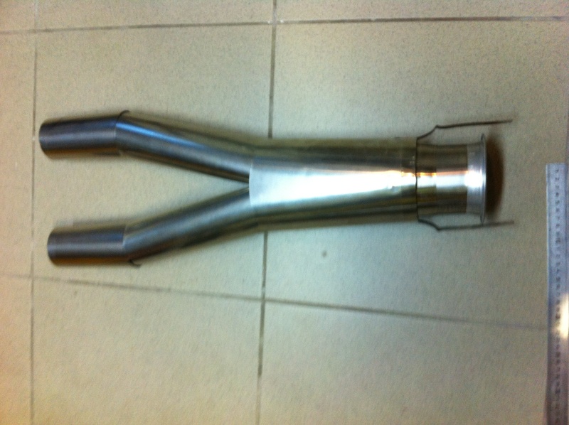
And the new personal setup. It's also too easy for gravity center, to access to the turbine and screw this one !
11-14-2012, 10:07 AM
#48
Thread Starter
My Feedback: (1)
It also depends on the turbine used as well.
With my king tech 140 and the stock pipe installed 1" from the exhaust tips my spacing is about 1/2 way in between the two posted pictures.
Now that I compare the three pics it appears almost 2/3 toward the forward position.
I will reinstall tonight and put cross brace in and post a picture for refrence.
I guess another important question would be if the pipe is spaced back from the tips by 1 inch will that be an issue? From the searches I don't see it being an issue. There is a lot of space from the pipe to the tail feathers.
11-14-2012, 10:51 AM
#49
Thread Starter
My Feedback: (1)
More progress last night. Started hingeing the main doors on the fuse.
Decided to use metal robart hinges for these and fasten with cyano. Previous fuse had all the hinges fastened with nuts and bolts. I wanted to get away from this and since I was putting new doors on it was the time.
My hope is that on an impact it will break away without much damage. I fly 99% on grass.
Looking at the Nose gear door I think I will start making one tonight. Otherwise I will have to wait for 5 weeks for one from FB jets. Too long of a wait for me.
The process.
1. Tape the door on in the correct spot. Make sure that the edge on the hinged side has enough clearance. I also like to bevel that side with a dremel so it doesn't interfere with opening and closing.
2. Roughen the door, fuse and hinges mounting surface.
3. Sand the hinges to fit on door properly. They were a bit too big for the mounting surface.
4. Remove Nuts and bots form hinge and replace with alignment tool.
5. Use Gel CA in 2 of the holes and use Kicker to make it set up on the door side first and then the fuse side.
6. Remove door from fuse and use more CA and kicker around perimeter and in other holes. Do the same on the fuse mounts.
7. Re install and check!
8. Hinges required a little bit of sanding where the hinge contacts the fuse. I used a small triangle file for this and did not need to remove much.
11-14-2012, 11:12 AM
#50
Thread Starter
My Feedback: (1)
Here is a final shot of One door complete and then both doors complete.
In the past I have used Epoxy and also "Goop" brand products for mounting Hinges. I like the goop as it's flexible and strong and will let go on a strong impact. This is my first time Using CA for Hinges and I like it. you could hold the hinge in place with a small screw driver or pick if required and use Kicker and it is quick. After I was done I put a significant force on the doors side to side and it did not let go.
Seems to be good!