


Jeti-duplex-ds-16-2.4-ghz
 12-28-2013, 07:02 PM
#251


Jim.. thanks for your detail explanation of the Double Path method. I recently received my CB200 with 3 R3 receivers one to be used and a remote switch. I bound each of the R3 in a Double Path method. Then I changed each of the receivers output to Ex-Bus. I have connected each receiver through output 4 of the R3 to the CB200 Rx1 and Rx2.
On the transmitter screen I see Double Path and after expanding the antenna screen I see A1, A2, A3 and A4 each at 9 and each receiver at 100%. Now my questions is when I disconnect one of the receivers I lose both telemetry reporting on both antennas and I get a signal loss warning, but checking the servo connected to CB200 it still works (as expected) through the connected receiver
I would like to know if a receiver is lost which one is lost? and what is the strength of the one still connected? is that possible
Thanks... David
 12-28-2013, 08:10 PM
#252
I think folks get a little confused with frame rates, updates speed, etc... Freqs, spectrum, and such..
The Jeti is a hybrid FHSS/DSSS system.. It uses a Digital spread Spectrum signal kinda like the original Spektrum DSM2 signals were, however it sweeps them in a Pseudo random order like FHSS, thereby spreading the power, and increasing the penetration rate.. Without getting too technical.. using this technique, and a 12 bit message, an update rate on the carrier of 2.4GHz is capable of creating 4096 resolution, so the radio can generate a ton of data on the carrier..
The receiver de multiplexes that data, and generates servo pulses in PPM format.. A serial ppm signal for instance needs a 4ms spacing between the last channel's pulse and the next trigger pulse "reset frame space" is what its called.. The pulse width is what drives the servo..
A servo receives one pulse, goes to that PW, and stays and listens until the next pulse comes as long as its hearing valid update rates.. servos can go down to 10 Millisec update rate..
The receiver decodes the data and sends individual pulses to each servo at a rate determined by capability or settings..
When you set 17 millisec in the Jeti Rx menu for instance, you are setting the Servo update rate.. Auto allows the rx to flex the rate with the data, and Transmitter set its to a lower fixed rate around 30Hz vice 100Hz.. don't confuse that with the carrier and data, that is simply the rate at which it generates changes.
When you use a Sat Receiver, it decodes a PPM stream, and in this case, the systems will slow down to accept 16 or the set number of channels.. around 2ms for each channel, and 4ms to rest... then repeat..
After receiving all this data, the receiver then can Group those pulses into up to 8 groups, but to keep the update rate reasonable, Jeti recommends 3 groups
The groups allow SERVOS to get their timing pulses at the same exact start timing.. so they all drive at the same time.. this helps them move together..
SO... on your model, my recommendation is to limit it to 3 groups.. Put any servos that must be together in the same group, like rudders ganged, dual ailerons or elevators.. Jeti recommends no more than 4 hi powered servos in a group because since they all move together, it hammers the power requirements at the same time.. so to spread the hammering of the system, put them in different groups..
so for example:
Group A: Dual Ailerons, Throttle
Group B: Elevators, smoke
Group C: Rudders, brakes, NWS, and Gear
Note that I didn't put any two groups that take a big load together..
Note that I didn't put a lot of stuff in the Elevator group or Aileron group. most important ones for quick response
SO..... If you have digital servos, You can set Auto in the Receiver speed menu, and 100Hz in the System Transmitter menu for both the Primary and secondary Duplex receivers, AND
If you keep your servos set up into 3 groups or less, the system can update up to 10ms best case, and 33ms worse case.. That will translate to latency or response to your inputs..
Hope that makes sense...goose
12-28-2013, 08:14 PM
#253
Jim.. thanks for your detail explanation of the Double Path method. I recently received my CB200 with 3 R3 receivers one to be used and a remote switch. I bound each of the R3 in a Double Path method. Then I changed each of the receivers output to Ex-Bus. I have connected each receiver through output 4 of the R3 to the CB200 Rx1 and Rx2.
On the transmitter screen I see Double Path and after expanding the antenna screen I see A1, A2, A3 and A4 each at 9 and each receiver at 100%. Now my questions is when I disconnect one of the receivers I lose both telemetry reporting on both antennas and I get a signal loss warning, but checking the servo connected to CB200 it still works (as expected) through the connected receiver
I would like to know if a receiver is lost which one is lost? and what is the strength of the one still connected? is that possible
Thanks... David
On the transmitter screen I see Double Path and after expanding the antenna screen I see A1, A2, A3 and A4 each at 9 and each receiver at 100%. Now my questions is when I disconnect one of the receivers I lose both telemetry reporting on both antennas and I get a signal loss warning, but checking the servo connected to CB200 it still works (as expected) through the connected receiver
I would like to know if a receiver is lost which one is lost? and what is the strength of the one still connected? is that possible
Thanks... David
Try plugging the receivers from their EXT ports into the RX port of the CB200, and see if anything is different.. You should be able to see the the CB200 in the device explorer this way.. You then use the CB200 EXT ports for telemetry stuff..
Last edited by gooseF22; 12-28-2013 at 08:16 PM.
12-29-2013, 12:45 AM
#254
Jim.. The only way I got the R3/RSW to work with CB200 was through port 4 of the R3/RSW which is the EXT port to Rx1 of CB200 and the other to Rx2... I tried other ports 1-3 and they do not pass signal or connect to the CB200... Once I turn on the CB200 I will see it in device explorer. I have changed port 14 to servo out put and port 15 to ext (telemetry ).. I used port 3 (control) of the third R3/RSW as the remote RC switch to turn on the CB200 instead of the magnetic switch
I wish when when one receiver was disconnected we would know which one and see the strength of the remaining connected one..
Thanks for your help.. And I enjoyed your findings... I think you should compile them and post them as one attachment as reference guide
David
I wish when when one receiver was disconnected we would know which one and see the strength of the remaining connected one..
Thanks for your help.. And I enjoyed your findings... I think you should compile them and post them as one attachment as reference guide
David
12-29-2013, 08:19 AM
#255
I should have read closer David.. Port 4 of the R3 is the data port.. 
We will look into programming in the CB200 to see if we can figure out how to make it tell you which data link is lost.. I am pretty sure it can be coded via morse code, but what IM not sure of is the priority of the sound files. Signal Lost takes the highest priority so It doesn't let it say the other commands, such as Receiver 1 Lost, receiver 2 lost..
Jim and I will look into this as we dig into the CB200 a little more.. I just got mine a couple days ago, and am on another road trip until next week..
Last edited by gooseF22; 12-29-2013 at 08:27 AM.
12-29-2013, 08:24 AM
#256
Also, separate topic, for those of you that have a separate Jeti Box Profi for your copilot to monitor and such..
It has only the capability to listen "monitor" mode to one receiver/transmitter traffic.. So, you will only be able to see telemetry that is on to the primary TX/RX link..
Not a factor if a single receiver, but if you have Dual Path, you won't see the secondary receiver on the JB Profi..nor any data links that are plugged into it..
To be sure, I plugged my Vario into my secondary receiver from the primary, and it disappeared from the JBprofi, then swapped it back, and it showed up..
Separately however, the JB emulator on the Transmitter sees both.. just touch the JB1 or JB2 button F5 during emulation to see either receiver.
12-29-2013, 09:50 AM
#259
Chris,
Dave Here..
There are two configurations for the CB200 with respect to the receivers..
1. EX MODE : Plugging the EX port 4 on the R3 into the CB200 RX1,2,
This setup requires the receivers to be put into EX output mode, just like you did already.. This is a bi directional comm bus, that provided input to the CB200, and provides a return path from the EX ports in the CB200 to send data..
Two wires needed.. R3 EXT port 4 to CB200 RX1/2 ports..
2. PPM Mode: Plugging the PPM port 3 into CB200 RX1,2
This setup requires the CB200 to be configured for PPM input, and the R3 to be configured for PPM output.
You must then use the PPM out port 3 (or any other receiver ppm out)
BUT, you must also run a 3rd wire from the CB200 EX port to one of the Receiver's EX port, so that the CB200 can provide telemetry..
As it stands right now, I prefer option 1..
Below is option 1- should help...
Last edited by gooseF22; 12-29-2013 at 09:59 AM.
12-29-2013, 11:46 AM
#261

I also followed the procedure outlined in post #238 and started with new from the box receivers, an R14 and and R5L and I also needed to install a bind plug to get the R5L to bind. After a bunch of fiddling and getting unexpected Sat1 PPM lost (I connected the R5L to Sat1 port) alarms, I appear to have everything working. As this is my first setup with this radio, I'd appreciate some feedback on the servo output configs that I chose. As I'm coming from a JR / Spektrum background, I'm used to channels 1 - 4 being Throttle, Aileron, Elevator and Rudder so that was how I mapped them. Since I have 4 Aileron servos I mapped channels 2 and 5 as Aileron 1, which I plan to connect to the right hand wing panels. Aileron 2 was set for channels 6 and 7. Channels 3 and 8 were set to Elevators 1 and Elevator 2 respectively. Since I have an Ignition Kill circuit in this plane I defined a channel called Ignition and assigned it to channel 9. As for servo groupings I assigned throttle, Rudder and Ignition to "Group A", the 4 Aileron channels to "Group B" and the Elevator servos to "Group C". My basic reasoning was that while the Throttle Rudder and Ignition channels really didn't need to be synchronized, I also couldn't see them being in the same group as causing a problem either as the ignition draw little power and will only change to kill the engine and the Throttle channel is very low load and shouldn't draw much current. I of course felt it was critical to have the Ailerons be updated simultaneously and the same for the Elevators so I gave each of them their own groups. Any constructive comments on why some of these decisions may not be such a good idea would be greatly appreciated.
 12-29-2013, 11:51 AM
#262
grouping and output sounds good to me wayne for what its worth.. I actually prefer similar controls side by side in the radio because I can see the displays better during setup..
The radio defaults front to back left to right.. I figure leave it alone and it will almost be the same every time in its default assignment of ports, but you can change it if you like
Why would you change ports? maybe if the servo wires were split into 2 bundles, one for the front one for the back, or side side for install.. something like that..
as you do it a few times, it gets easier to setup.. I ended up copying model to model and modding it from there to keep my sounds the same..
12-29-2013, 11:56 AM
#263
Banned
Join Date: Jul 2013
Location: , UNITED KINGDOM
Posts: 454
Likes: 0
Received 0 Likes
on
0 Posts
If the programming and the instructions were any good I would not think that this thread would be necessary. Obviously people cant understand the system or the instructions
12-29-2013, 12:14 PM
#264
Hey Jetflyer,
The system has a lot of capability that is new to a lot of people.. The instructions could be better yes, but thats the case with every manufacturer I have encountered..
We are all learning here...If you want to participate or ask constructively, bring it..
But If you are on here slamming Jeti, take it elsewhere where there is an audience.. it aint here..
12-29-2013, 12:16 PM
#265
grouping and output sounds good to me wayne for what its worth.. I actually prefer similar controls side by side in the radio because I can see the displays better during setup..
The radio defaults front to back left to right.. I figure leave it alone and it will almost be the same every time in its default assignment of ports, but you can change it if you like
Why would you change ports? maybe if the servo wires were split into 2 bundles, one for the front one for the back, or side side for install.. something like that..
as you do it a few times, it gets easier to setup.. I ended up copying model to model and modding it from there to keep my sounds the same..
The radio defaults front to back left to right.. I figure leave it alone and it will almost be the same every time in its default assignment of ports, but you can change it if you like
Why would you change ports? maybe if the servo wires were split into 2 bundles, one for the front one for the back, or side side for install.. something like that..
as you do it a few times, it gets easier to setup.. I ended up copying model to model and modding it from there to keep my sounds the same..
First of all, thanks for taking the time to reply and share your thoughts. As the radio really doesn't support a 4 Aileron, no flaps wing type, I opted for a No flaps, 2 Aileron wing type as someone on another forum suggested. In order to get 4 separate Aileron channels, I needed to go in and modify the default mapping as it only assigned 2 Aileron channels. Also, coming from JR / Spektrum for the past many years, I've simply gotten used to certain channels having a certain assignment and if for example, one of the Aileron servos on my right hand wing panel stops working, I start tracing wires from either channel 2 or channel 5 depending if it's the inboard or outboard servo. It's simply a matter of my planes always having been wired that way. I also hoped that by keeping the channel mappings similar to my old receivers that I would simply be able to move servo wires from channel 1 of the old receiver to channel 1 of the new receiver, etc and hopefully simplify the change over. Of course at this point I'm converting existing models which are already wired but if significant benefits of doing things differently come to light then I'm certainly willing to change my evil ways
Last edited by wfield0455; 12-29-2013 at 12:19 PM.
12-29-2013, 01:07 PM
#266

My Feedback: (10)

Join Date: Oct 2003
Location: Webster,
NY
Posts: 227
Likes: 0
Received 0 Likes
on
0 Posts
I agree with Dave. Your setup sounds fine to me and I don't think you will notice any delays at all. I had the same reaction as you did regarding the servo assignments coming from a JR 12X. I have gotten used to just letting the "Auto" function do the assignments and add channels where necessary, this way the setups are usually very similar. I often use a Powerbox which will let me match channels which also means that the output is simultaneous and I typically like that on my elevators, this might also be something to consider. I'm not into the CB so I don't know if it does that as well or not.
Jetflyer3000, your favorite thread on RCG has over 18'000 posts! In your own logic, what does that tell you about that system?
Chris
Jetflyer3000, your favorite thread on RCG has over 18'000 posts! In your own logic, what does that tell you about that system?
Chris
12-29-2013, 02:34 PM
#267
Goose,
First of all, thanks for taking the time to reply and share your thoughts. As the radio really doesn't support a 4 Aileron, no flaps wing type, I opted for a No flaps, 2 Aileron wing type as someone on another forum suggested. In order to get 4 separate Aileron channels, I needed to go in and modify the default mapping as it only assigned 2 Aileron channels. Also, coming from JR / Spektrum for the past many years, I've simply gotten used to certain channels having a certain assignment and if for example, one of the Aileron servos on my right hand wing panel stops working, I start tracing wires from either channel 2 or channel 5 depending if it's the inboard or outboard servo. It's simply a matter of my planes always having been wired that way. I also hoped that by keeping the channel mappings similar to my old receivers that I would simply be able to move servo wires from channel 1 of the old receiver to channel 1 of the new receiver, etc and hopefully simplify the change over. Of course at this point I'm converting existing models which are already wired but if significant benefits of doing things differently come to light then I'm certainly willing to change my evil ways
First of all, thanks for taking the time to reply and share your thoughts. As the radio really doesn't support a 4 Aileron, no flaps wing type, I opted for a No flaps, 2 Aileron wing type as someone on another forum suggested. In order to get 4 separate Aileron channels, I needed to go in and modify the default mapping as it only assigned 2 Aileron channels. Also, coming from JR / Spektrum for the past many years, I've simply gotten used to certain channels having a certain assignment and if for example, one of the Aileron servos on my right hand wing panel stops working, I start tracing wires from either channel 2 or channel 5 depending if it's the inboard or outboard servo. It's simply a matter of my planes always having been wired that way. I also hoped that by keeping the channel mappings similar to my old receivers that I would simply be able to move servo wires from channel 1 of the old receiver to channel 1 of the new receiver, etc and hopefully simplify the change over. Of course at this point I'm converting existing models which are already wired but if significant benefits of doing things differently come to light then I'm certainly willing to change my evil ways
I try to keep my jets close to the same scheme.. But the neat thing is you can map it anyway you want from a channelization, and fix it with groups and function curves..Now I just write the channelization on my big board and take a picture of it when done.. then its in my phone forever and I have it, but I do try to keep the same for the most part.. but I program JR, Futuba, and now Jeti radios helping others, so I had a lot to learn..
The cool thing about Jeti is groups.. that allows servo timing to be customized..
I think I heard the 4 servo wing thing will get addressed in an upcoming release..as well as fixing the double servo tuning better

 12-30-2013, 06:21 PM
#270
Or No switch in the unit with a separate Power switch like the wolverine.. the unit defaults to On with no switch installed..
12-31-2013, 05:33 AM
#271
One thing I haven't seen mentioned is power draw of the CB200 while in the off state. Since it uses a soft switch and can be turned on/off remotely (with the proper receiver attached) it must be drawing some minimal amount of power as long as the batteries are connected. I haven't seen any documentation (but may have missed it) stating that it's important to disconnect the batteries at the end of a day of flying but I assume it is important to do so to prevent completely discharging the batteries after a period of inactivity????
12-31-2013, 06:23 AM
#272
Senior Member
Join Date: Jun 2013
Location: , FL
Posts: 423
Likes: 0
Received 0 Likes
on
0 Posts
One thing I haven't seen mentioned is power draw of the CB200 while in the off state. Since it uses a soft switch and can be turned on/off remotely (with the proper receiver attached) it must be drawing some minimal amount of power as long as the batteries are connected. I haven't seen any documentation (but may have missed it) stating that it's important to disconnect the batteries at the end of a day of flying but I assume it is important to do so to prevent completely discharging the batteries after a period of inactivity????
Zb/Jeti USA
12-31-2013, 11:50 AM
#273
12-31-2013, 02:09 PM
#274
As I recall, the JR / Spektrum PowerSafe receivers draw something like 400 - 500 micro amps when powered down. Since the Central Box needs to maintain standby power to an R3 if you want to be able to turn it on from the transmitter I suspect it draws a bit more than some other devices.
01-05-2014, 06:31 AM
#275
Senior Member
Join Date: Jun 2013
Location: , FL
Posts: 423
Likes: 0
Received 0 Likes
on
0 Posts
Hi Guys,
If any of you guys on the west coast are planning on attending stop by the Jeti USA booth and say hello.
Zb/Jeti USA

Only 7 Days Until AMA Expo 2014, Ontario, California!!!
Stop by to see us at the AMA Expo, Ontario, California, January 10-12, 2014 (Booth 411-413).
We packed 10x Creates full of presents and surprises.
Expo 2014 is bigger and better than ever with more than 100 exhibitors featuring over 230 booths. This includes 18 new exhibitors showcasing and selling the latest in model flying products. The swap shop is bigger too with 34 tables of great finds and one-of-a-kind items. Add special guest speakers, an AMA membership meeting, FAA forum, flying demos, and exhibits such as a Spruce Goose scale flying model with a 25-foot wingspan and you have a great Expo experience just waiting for you!
Pictures from AMA EXPO 2013!!!


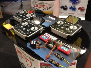

[h=2]Stop By to See & Play In Person with Brand New[/h][h=3]Jeti Duplex DS-14 2.4GHz, 14 Channel Radio System[/h]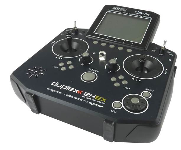
If any of you guys on the west coast are planning on attending stop by the Jeti USA booth and say hello.
Zb/Jeti USA
Only 7 Days Until AMA Expo 2014, Ontario, California!!!
Stop by to see us at the AMA Expo, Ontario, California, January 10-12, 2014 (Booth 411-413).
We packed 10x Creates full of presents and surprises.
Expo 2014 is bigger and better than ever with more than 100 exhibitors featuring over 230 booths. This includes 18 new exhibitors showcasing and selling the latest in model flying products. The swap shop is bigger too with 34 tables of great finds and one-of-a-kind items. Add special guest speakers, an AMA membership meeting, FAA forum, flying demos, and exhibits such as a Spruce Goose scale flying model with a 25-foot wingspan and you have a great Expo experience just waiting for you!
Pictures from AMA EXPO 2013!!!
[h=2]Stop By to See & Play In Person with Brand New[/h][h=3]Jeti Duplex DS-14 2.4GHz, 14 Channel Radio System[/h]
Last edited by Jeti USA; 01-05-2014 at 06:38 AM.

