


Jeti-duplex-ds-16-2.4-ghz
 04-20-2015, 02:07 PM
#1701
Senior Member
Join Date: Jan 2009
Location: au dessus des nuages, FRANCE
Posts: 115
Likes: 0
Received 0 Likes
on
0 Posts
Hi, I am a finger flyer, this is my first real tray, so I will not now if I like it, until I actually fly with it. The tray feels pritty good, but the sliders feel ackward at first feel.
Rcpete
Also, anyone know when Behotec and Jet Central turbine sensers will come out, would be cool to do adjustments to the turbine from the transmitter.
Rcpete
Also, anyone know when Behotec and Jet Central turbine sensers will come out, would be cool to do adjustments to the turbine from the transmitter.
There is another solution that works with Behotec and JetCentral
https://sites.google.com/site/wbtele...tebox-for-jeti

 04-20-2015, 05:37 PM
#1704

My Feedback: (53)

If you are a "pincher", probably the DC series would have been the better choice, because you can reach the sliders without breaking your fingers. I also have a DC-16 and a 14 in a tray, and I prefer the feel of the tray type a lot over the handheld 14 in a tray, although it is a lot heavier and bulkier. But it all comes down to personal preference, it might just take some time to get used to it.
The Vspeak converter works with all Hornet ECUs, that includes Behotec turbines as well (see http://www.vspeak-modell.de/en/ecu-converter/hornet). Gaspar @ Xicoy also has his own telemetry module that works with Jetcentral turbines (see http://www.xicoy.com/catalog/product...roducts_id=336), but I don't know if it allows to change the ECU settings through the radio.
Thomas
04-21-2015, 02:45 AM
#1705
04-21-2015, 05:26 AM
#1706
Senior Member
Join Date: Jun 2013
Location: , FL
Posts: 423
Likes: 0
Received 0 Likes
on
0 Posts
Zb/jeti USA
04-21-2015, 05:51 AM
#1707
04-21-2015, 07:12 AM
#1708

I really don't mind using the GSU if for some reason I need to tweak something like pump voltage, etc, but during normal startup, the Xicoy unit displays RPM, ETC, etc, right on my DS16s front panel which is very convenient. Additional support via device explorer would of course be nice, but I think Gaspar did a rather nice job of balancing simplicity of use and the features provided by this interface.
04-21-2015, 11:28 AM
#1709
My Feedback: (53)
I really don't mind using the GSU if for some reason I need to tweak something like pump voltage, etc, but during normal startup, the Xicoy unit displays RPM, ETC, etc, right on my DS16s front panel which is very convenient. Additional support via device explorer would of course be nice, but I think Gaspar did a rather nice job of balancing simplicity of use and the features provided by this interface.
Its a great telemetry device which at a very decent price point....
 04-21-2015, 12:21 PM
#1712
It is easy to install or change the switches, in the case of the DS14 you have to remove the two plastic plugs by squeezing the two tabs on the back side and then they will come right out. DO NOT try to just push them out or you will damage the face panel. The procedure is outlined in the manual. Make sure your order "DS" switches as the "DC" switches are different.
04-21-2015, 12:58 PM
#1714

Join Date: Oct 2007
Location: Montreal, QC, CANADA
Posts: 170
Likes: 0
Received 0 Likes
on
0 Posts
Just one more just in case, If you ever need some stick switches (probably never on a DS) you will have soldering to do. I did some on my DC-16, as long as you have a soldering iron with a small tip and are not bad at soldering, you are ok.
04-21-2015, 06:38 PM
#1715
My Feedback: (1)
Join Date: Jun 2005
Location: Hong Kong
Posts: 167
Likes: 0
Received 0 Likes
on
0 Posts
I find the fact that the Device explorer page always goes back to the initialisation screen is a pain. What would be nice is if it stayed on the page you left it on, after each TX/Xicoy power cycle.
Secondly, I find there is a big 'LAG' between pressing the desired button, and seeing the change on your Jeti. I'm not sure what the refresh rate is, but it would be nice if it were quicker.
That said.... it's awesome to see the engine parameter's on the DS16. I'm sure it'll only get better with time.
04-22-2015, 02:28 PM
#1716

Asked the same question on rcg but, thought it might reach the jet guys quicker here.
What are you fellows doing for an alternative throttle trim? in particular for turbines.
I have tried to switch my throttle trim to both a switch and an rotary knob. I reduce the trim throw to 25% but, the problem that I'm seeing is that the trim will equally affect the high throttle and the low throttle.
for eg. if you are at full throttle on the stick and reduce your trim, it will reduce your high throttle. Throttle trim should effect only the low throttle. What am I missing in the set up?
Thanks
Mike
04-22-2015, 03:18 PM
#1717
Thanks for the info guys. Another question: I do not have a PC right now (or one that is working reliably), I plan to get a another cheapo laptop soon, but right now all I have is a chromebook. Is it necessary to have a PC to get a DS 14 up and running? For registration etc.
04-22-2015, 03:31 PM
#1718
Thanks for the info guys. Another question: I do not have a PC right now (or one that is working reliably), I plan to get a another cheapo laptop soon, but right now all I have is a chromebook. Is it necessary to have a PC to get a DS 14 up and running? For registration etc.
04-22-2015, 04:04 PM
#1721
Thanks Bob, I do know how to set the throttle trim to the trim buttons. I wish to assign it to another switch or knob. You can do this under Functions Assignment but, as I said, the trim effects both high and low throttle. Does anyone have a "fix" for this?
Mike
Mike
04-22-2015, 04:41 PM
#1722
Another option would be to simply disconnect the throttle trim in the trim menu completely and create a Throttle to Throttle mix with a value of 25% or 50% depending on the trim change desired and use the desired switch to activate the mix.
A final solution would be to use Advanced Properties, Other Model Options and select the desired switch as the "Throttle Cut" switch, then set the Throttle-Cut output value to -125% or something reasonable. I think I like the last one best but I didn't think of it until I had posted the other solutions :^)
One final comment on the Throttle-Cut solution, it will drive the throttle channel to the "kill" position, even from full throttle so you should use one of the locking "safety" switches if you go that route..
Wayne
[ATTACH]2091178[/IMG]
[ATTACH]2091179[/IMG]
Last edited by wfield0455; 04-22-2015 at 05:16 PM.
04-22-2015, 06:53 PM
#1724
Senior Member
Join Date: Jun 2013
Location: , FL
Posts: 423
Likes: 0
Received 0 Likes
on
0 Posts
Some reading for the weekend.
We just received the pdf. manual of the Central Box 400, please excuse English still working copy. But we are already working on the revision. Jeti promised to have them mid may.
Zb/Jeti USA
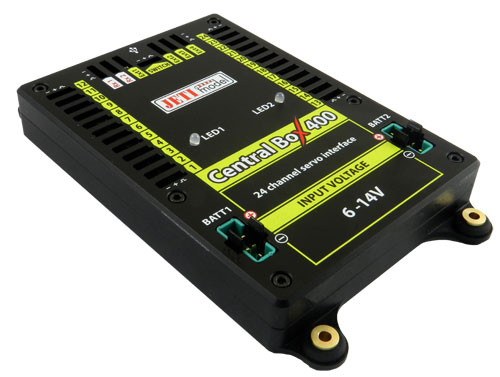
The Central Box 400 is a switchboard designed for the complete management of servos in large to giant models with an emphasis on safety. The Central Box 400 has a unique design that provides overload protection at each servo output. Independent, very powerful BEC stabilizer (battery eliminator circuit) for each battery input makes the Central Box an optimal solution to connect 24 servos. The Central Box 400 can manage the batteries and fully supports the JETI EX telemetry system. Up to two receivers with serial (PPM, EX Bus, UDI) output can be connected to the Central Box 400. With JETI DC/DS transmitter, the full potential of the Central Box can be used, such as an easy way to configure the Central Box, EX telemetry, and very fast servo response.
1.1 Attributes
- Two independent high-powered BEC�s for voltage stabilization of servos
- overload protection on each channel
- overload protection on Rx, Ext, and Switch outputs
- possibility to connect up to 2 receivers with serial interface (PPM, EX Bus, UDI)
- built-in Expander function with a possibility to connect JETI EX sensors
- input for magnetic switch or RC switch
- accumulators connected via MPX connector
- stabilized voltage output via a pair of MPX connectors
- 100Hz mode of servo outputs (10ms period)
- supports EX telemetry (voltage, current, capacity, and temperature measurement, overload indication, ...)
- internal memory for storage of telemetry data
- USB connectivity for connection to PC
- easy settings changes via DC/DS transmitter
- firmware updates
- suitable for use with high voltage (HV) servos
- robust metal construction with mounting holes
- LED status indication
- each output is individually configurable (channel assignment, trim, reverse, ATV)
Central Box 400 has 24 outputs for servos with individual overload protection. Moreover, outputs Y17-Y24 can be configured as:
� servo outputs
� logical inputs
� logical outputs
Control signals generated by the Central Box to servos have 5V. This solution brings reliable signal transfer for servos for longer distances.
Ext1 - Ext4 ports can be configured for use as:
� inputs for telemetry sensors
� EX Bus expanders - used for connecting devices which support the EX Bus protocol (the Central Box, a sensor,...)
Ext4 - slot is also used as an output to connect a JETIBOX to configure the Central Box and for the firmware update connection
Rx1 - primary input for connecting receivers with serial output (EX, PPM, UDI)
Rx2 - secondary (backup) input for connecting receivers with serial output (EX bus, PPM, UDI)
Switch slot is reserved for connecting magnetic switch or RC Switch
BEC output serves as the output for stabilized voltage to power supply other Central Boxes that can be power supplied from the Central Box 400. The voltage at the output has the same level as the voltage for supplying the servos. Voltage for the servo outputs is adjustable in the range of 5-8V with 0.1V step.
For more safety the Central Box 400 contains two BEC connected in parallel regulators. Information about the correct power supply and a faultless condition of individual branches is indicated by green LED and also by telemetry. It is not recommended to use the BEC output for direct power supply of servos or receivers with servos. These devices are not individually protected. In case of overloading one element of the branch supplied from the BEC output, the entire branch is disconnected. BEC output current limit is 15A.
Central Box 400 is fitted with internal memory of 8 MB. This memory is used to store the telemetry from the Central Box and from the sensors connected to it. The memory has a standard FAT32 file system. The files containing the telemetry data are located in the Log. directory. The file name consists of its serial number and a log file extension, for example. "1.log". When creating a new file, the number in the file name is increased by 1 compared to the previous title. The highest number in the file name indicates the most recent record.
If the memory is full, the oldest file is deleted and the storage continues. The memory has a capacity of about 1 hour recording at full capacity, i.e. 4 telemetry sensors connected to the Central Box.
The telemetry recording starts automatically if the Central Box detects a receiver providing the information on channels on Rx1 or Rx2 pins. The recording stops automatically when you switch off the Central Box.
We just received the pdf. manual of the Central Box 400, please excuse English still working copy. But we are already working on the revision. Jeti promised to have them mid may.
Zb/Jeti USA
The Central Box 400 is a switchboard designed for the complete management of servos in large to giant models with an emphasis on safety. The Central Box 400 has a unique design that provides overload protection at each servo output. Independent, very powerful BEC stabilizer (battery eliminator circuit) for each battery input makes the Central Box an optimal solution to connect 24 servos. The Central Box 400 can manage the batteries and fully supports the JETI EX telemetry system. Up to two receivers with serial (PPM, EX Bus, UDI) output can be connected to the Central Box 400. With JETI DC/DS transmitter, the full potential of the Central Box can be used, such as an easy way to configure the Central Box, EX telemetry, and very fast servo response.
1.1 Attributes
- Two independent high-powered BEC�s for voltage stabilization of servos
- overload protection on each channel
- overload protection on Rx, Ext, and Switch outputs
- possibility to connect up to 2 receivers with serial interface (PPM, EX Bus, UDI)
- built-in Expander function with a possibility to connect JETI EX sensors
- input for magnetic switch or RC switch
- accumulators connected via MPX connector
- stabilized voltage output via a pair of MPX connectors
- 100Hz mode of servo outputs (10ms period)
- supports EX telemetry (voltage, current, capacity, and temperature measurement, overload indication, ...)
- internal memory for storage of telemetry data
- USB connectivity for connection to PC
- easy settings changes via DC/DS transmitter
- firmware updates
- suitable for use with high voltage (HV) servos
- robust metal construction with mounting holes
- LED status indication
- each output is individually configurable (channel assignment, trim, reverse, ATV)
Central Box 400 has 24 outputs for servos with individual overload protection. Moreover, outputs Y17-Y24 can be configured as:
� servo outputs
� logical inputs
� logical outputs
Control signals generated by the Central Box to servos have 5V. This solution brings reliable signal transfer for servos for longer distances.
Ext1 - Ext4 ports can be configured for use as:
� inputs for telemetry sensors
� EX Bus expanders - used for connecting devices which support the EX Bus protocol (the Central Box, a sensor,...)
Ext4 - slot is also used as an output to connect a JETIBOX to configure the Central Box and for the firmware update connection
Rx1 - primary input for connecting receivers with serial output (EX, PPM, UDI)
Rx2 - secondary (backup) input for connecting receivers with serial output (EX bus, PPM, UDI)
Switch slot is reserved for connecting magnetic switch or RC Switch
BEC output serves as the output for stabilized voltage to power supply other Central Boxes that can be power supplied from the Central Box 400. The voltage at the output has the same level as the voltage for supplying the servos. Voltage for the servo outputs is adjustable in the range of 5-8V with 0.1V step.
For more safety the Central Box 400 contains two BEC connected in parallel regulators. Information about the correct power supply and a faultless condition of individual branches is indicated by green LED and also by telemetry. It is not recommended to use the BEC output for direct power supply of servos or receivers with servos. These devices are not individually protected. In case of overloading one element of the branch supplied from the BEC output, the entire branch is disconnected. BEC output current limit is 15A.
Central Box 400 is fitted with internal memory of 8 MB. This memory is used to store the telemetry from the Central Box and from the sensors connected to it. The memory has a standard FAT32 file system. The files containing the telemetry data are located in the Log. directory. The file name consists of its serial number and a log file extension, for example. "1.log". When creating a new file, the number in the file name is increased by 1 compared to the previous title. The highest number in the file name indicates the most recent record.
If the memory is full, the oldest file is deleted and the storage continues. The memory has a capacity of about 1 hour recording at full capacity, i.e. 4 telemetry sensors connected to the Central Box.
The telemetry recording starts automatically if the Central Box detects a receiver providing the information on channels on Rx1 or Rx2 pins. The recording stops automatically when you switch off the Central Box.