


The Making of Xtreme ARF F100 D Super Sabre


 01-08-2015, 01:52 PM
#302

My Feedback: (1)
Join Date: Jul 2002
Location: SevenoaksKent, UNITED KINGDOM
Posts: 5,193
Likes: 0
Received 0 Likes
on
0 Posts
Bit of feedback. You gotta paint the reg numbers etc rather than use black stick-on vinyl. You can see the pretty penny nose art and lettering is cut from vinyl from several feet away in that pic. Use the vinyl cutter to cut a paint mask instead and then blow over it with paint quickly. You guys clearly have the paint talent to do it so why spoil things with yucky vinyl stick ons? Just think it will help take an already good looking product up another notch
01-09-2015, 01:40 AM
#303

Now with the abundance of telemetry we should be able to see stall airspeed and G loads reached as well as lots of other data if the investment is made.
01-09-2015, 03:35 AM
#304
I have looked at all the pictures on the XArf website as well as here on RCU. I'm Xtremely impressed with the quality. Please do not mistake any of my questions as derogatory. I think the more a manufacturer can share about its product, the better. We are not all engineers or designers. Most of us have gained an education of what fails on jets from flying and from sharing post crash information. Usually it's a pilot error, but sometimes it's a design or construction issue. XArf appears to be on a completely different level than was FEJ.
I am pleased that XArf recognizes the importance of communication and the sharing of information.
Our club lost an AT-3 due to a stabilator break away. The airplane had completed three gentle flights and was level at 50% power when the catastrophic failure occurred.
The post crash inspection found a 3mm screw against a balsa block to absorb rotation loads.
I would like to see what the stabilator looks like and how the rotational loads are transmitted to the shaft. The picture below isn't clearly showing how everything is connected. To see this without glue would be helpful.

Secondly, it was requested early on to see the internals of a wing. I'm specifically interested in how the retract attaches to the structure.
Third, At what weight did the static wing load test cause failure?
I also noticed from the pictures there is an absence of carbon fiber in the longitudinal axis of the fuselage. There are considerable bending stresses. If no CF is used, have you used a heavier weight of Fglass cloth in the layup?
Here is an example of CF tapes running full length. Four tapes running longitudinalally from nose to tail. Positioned roughly at 11,1,7 and 5 o'clock.
For example
And new while we are on the subject of quality I'm not happy with the SM 104. Unfortunately the options are limited. The good news is that SM did extensive testing and their quality proves airworthy. It's simply better if hidden with a coat of paint.
I am pleased that XArf recognizes the importance of communication and the sharing of information.
Our club lost an AT-3 due to a stabilator break away. The airplane had completed three gentle flights and was level at 50% power when the catastrophic failure occurred.
The post crash inspection found a 3mm screw against a balsa block to absorb rotation loads.
I would like to see what the stabilator looks like and how the rotational loads are transmitted to the shaft. The picture below isn't clearly showing how everything is connected. To see this without glue would be helpful.
Secondly, it was requested early on to see the internals of a wing. I'm specifically interested in how the retract attaches to the structure.
Third, At what weight did the static wing load test cause failure?
I also noticed from the pictures there is an absence of carbon fiber in the longitudinal axis of the fuselage. There are considerable bending stresses. If no CF is used, have you used a heavier weight of Fglass cloth in the layup?
Here is an example of CF tapes running full length. Four tapes running longitudinalally from nose to tail. Positioned roughly at 11,1,7 and 5 o'clock.
For example
And new while we are on the subject of quality I'm not happy with the SM 104. Unfortunately the options are limited. The good news is that SM did extensive testing and their quality proves airworthy. It's simply better if hidden with a coat of paint.
 01-10-2015, 05:54 AM
#306
Bit of feedback. You gotta paint the reg numbers etc rather than use black stick-on vinyl. You can see the pretty penny nose art and lettering is cut from vinyl from several feet away in that pic. Use the vinyl cutter to cut a paint mask instead and then blow over it with paint quickly. You guys clearly have the paint talent to do it so why spoil things with yucky vinyl stick ons? Just think it will help take an already good looking product up another notch
01-10-2015, 10:10 AM
#307
My Feedback: (1)
Join Date: Jul 2002
Location: SevenoaksKent, UNITED KINGDOM
Posts: 5,193
Likes: 0
Received 0 Likes
on
0 Posts
Oh, OK. It just looks really thick!
Are these insignias painted?? They look ever so rough. It's little things like this (for me) that put me off. Not knocking, just pointing out areas that are possibly costing sales.

Are these insignias painted?? They look ever so rough. It's little things like this (for me) that put me off. Not knocking, just pointing out areas that are possibly costing sales.
01-10-2015, 08:06 PM
#308
Please read the factory post # 297, this one still needs finishing and clear coat, now as they are no mass production, Xtremearf attends to the customers orders if they want half of the emblem, rough of it, etc..., then it will be done otherwise if no request was made by the customer they will follow the full scale one, so for example if in the full scale one has a lettering upside down it will be reproduce as it is.
01-12-2015, 04:18 AM
#309
I have looked at all the pictures on the XArf website as well as here on RCU. I'm Xtremely impressed with the quality. Please do not mistake any of my questions as derogatory. I think the more a manufacturer can share about its product, the better. We are not all engineers or designers. Most of us have gained an education of what fails on jets from flying and from sharing post crash information. Usually it's a pilot error, but sometimes it's a design or construction issue. XArf appears to be on a completely different level than was FEJ.
I am pleased that XArf recognizes the importance of communication and the sharing of information.
Our club lost an AT-3 due to a stabilator break away. The airplane had completed three gentle flights and was level at 50% power when the catastrophic failure occurred.
The post crash inspection found a 3mm screw against a balsa block to absorb rotation loads.
I would like to see what the stabilator looks like and how the rotational loads are transmitted to the shaft. The picture below isn't clearly showing how everything is connected. To see this without glue would be helpful.
Secondly, it was requested early on to see the internals of a wing. I'm specifically interested in how the retract attaches to the structure.
Third, At what weight did the static wing load test cause failure?
I also noticed from the pictures there is an absence of carbon fiber in the longitudinal axis of the fuselage. There are considerable bending stresses. If no CF is used, have you used a heavier weight of Fglass cloth in the layup?
Here is an example of CF tapes running full length. Four tapes running longitudinalally from nose to tail. Positioned roughly at 11,1,7 and 5 o'clock.
For example
And new while we are on the subject of quality I'm not happy with the SM 104. Unfortunately the options are limited. The good news is that SM did extensive testing and their quality proves airworthy. It's simply better if hidden with a coat of paint.
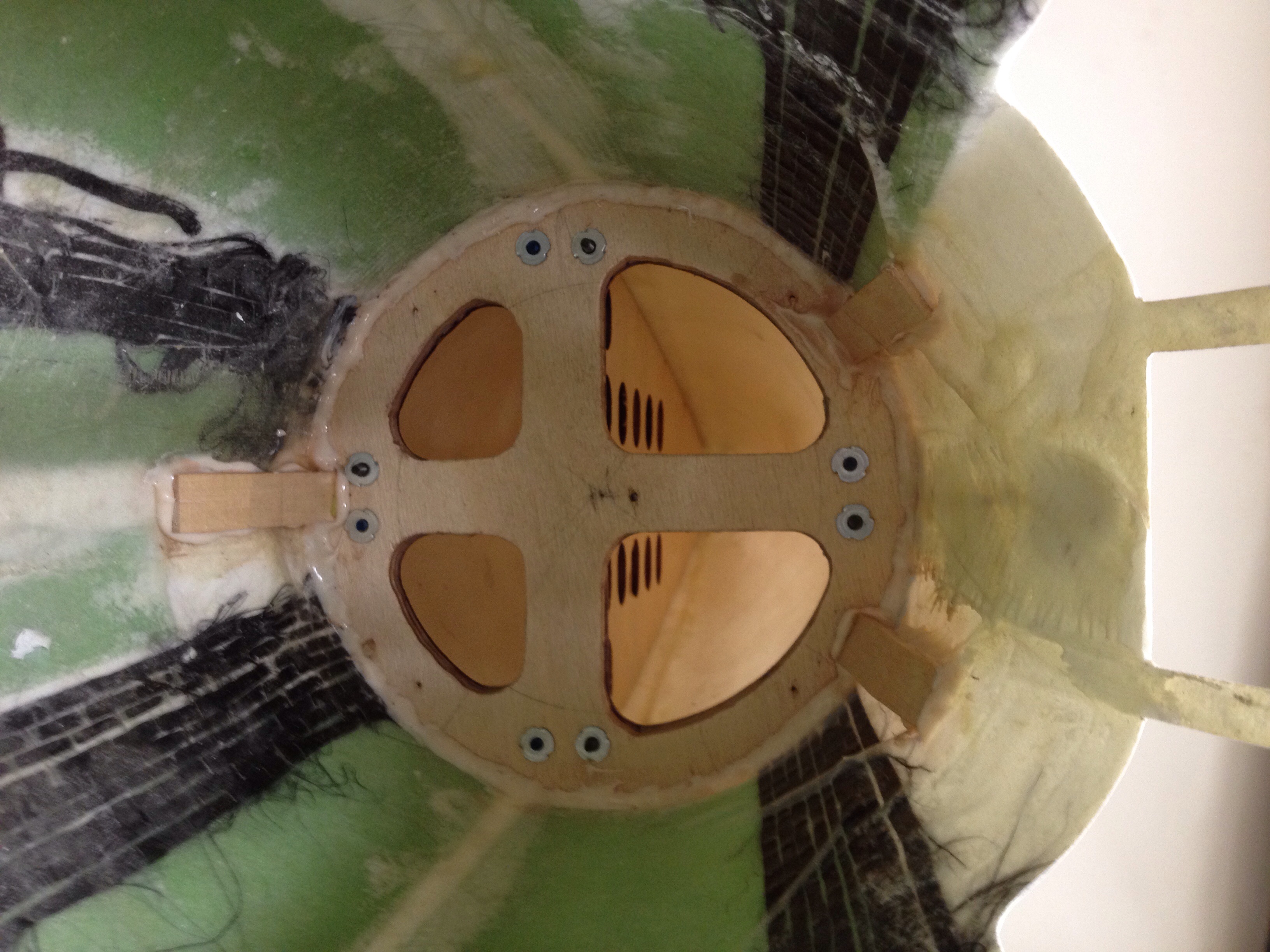
First : I zoon the stab for you and mark the way it work and the way the load are distributed, see picture:
The shaft formers are locked in place by to slots on the ribs reinforced with doubler FG/Kevlar plates, the skins ( bottom and top) are reinforced with heavy CF.
Second: I will try to get a picture of the wings before they close one.
Third: The fact that you do not see any CF reinforcement does not mean that it is not there, thing is they do it neat, the layup is FG/CF/Airex/FG so CF is inside the composite and it is not shown, take a look on my thread http://www.rcuniverse.com/forum/rc-j...hawk-t1-2.html look at post # 39 and you will understand.
01-15-2015, 07:09 PM
#318
01-16-2015, 04:48 AM
#321
I decide to post this Xtreme ARF F100D in the Sea Camo color scheme because I research this plane and this one has a history:
The "Hun" carries serial number 56-3440 she was build in !957 and she was delivered in December of the same year to the 506th FBW, she was then passed to the 413th FDW four months later and allocated at George AFB, the she was re-designated to the 31st TFW in 1959, the "Hun" wore the colorful markings of the 308th TFS/31st TFW

These color scheme were replaced by the all white color scheme for high altitude testes conducted from Aviano AB in 1960, By late 1965 the fighter was at Bien Hoa with the 307th TFS having served with 8th TFW at Itazuke, Japan. Moving to 308th TFS in 1966, 56-3440 was transferred to the 531th TFS/3rd TFW "Ramrods" in 1968 were it was painted in the sea camo color scheme and got the "CP" code on the tail (this is our customer plane)

Subsequent assigned to the 90th TFS and then adopt the "CB" tail code, then she was moved to the 524th TFS/27th TFW were it gets the "CD" tail code at Canon AFB, she finish her missions in July 19, 1972. A final tour with Michigan ANG's 107th TFS at Selfridge Air National Guard air base now she rest at the Smithsonian Air and Space Museum it was refit and shows now the "CB" tail code.

and this is our pictures:


The "Hun" carries serial number 56-3440 she was build in !957 and she was delivered in December of the same year to the 506th FBW, she was then passed to the 413th FDW four months later and allocated at George AFB, the she was re-designated to the 31st TFW in 1959, the "Hun" wore the colorful markings of the 308th TFS/31st TFW
These color scheme were replaced by the all white color scheme for high altitude testes conducted from Aviano AB in 1960, By late 1965 the fighter was at Bien Hoa with the 307th TFS having served with 8th TFW at Itazuke, Japan. Moving to 308th TFS in 1966, 56-3440 was transferred to the 531th TFS/3rd TFW "Ramrods" in 1968 were it was painted in the sea camo color scheme and got the "CP" code on the tail (this is our customer plane)
Subsequent assigned to the 90th TFS and then adopt the "CB" tail code, then she was moved to the 524th TFS/27th TFW were it gets the "CD" tail code at Canon AFB, she finish her missions in July 19, 1972. A final tour with Michigan ANG's 107th TFS at Selfridge Air National Guard air base now she rest at the Smithsonian Air and Space Museum it was refit and shows now the "CB" tail code.
and this is our pictures:
01-18-2015, 06:47 AM
#322


Join Date: Nov 2009
Location: AUSTINTOWN, OH
Posts: 564
Likes: 0
Received 0 Likes
on
0 Posts
HI All, Yesterday Jim Hiller and myself were in Akron so we stopped by the MAPS Air Museum that is only 50 miles from us. We walked in to see them cleaning off the snow on a F-100 they just brought in from the cold!! WOW what great timing and luck!!! Here are some pics. The guy with the gray hair in one of the pics was a F-100 pilot so he had all kind of GREAT info!! We will be going back this summer with our F-100 for some pics together.
Thanks Billy D
Thanks Billy D


