


2.6m F-117 NightHawk, Twin SimJet 2300 - Build form scratch.
 02-02-2015, 04:16 PM
#26
Member
Thread Starter

Join Date: Sep 2005
Location: Perth, AUSTRALIA
Posts: 55
Likes: 0
Received 0 Likes
on
0 Posts
Hello
First, I've to correct something that I didn't mention from the beginning.
This project is a joined efforts and funds between me and my best friend Bob. I'm sorry mate that I didn't mention your name from the first post.
So all the work done is a result of a lot of brain storming between both of us.
Last weekend we started on the fuselage. We are using dupron foam to create all the templates of the internal structure and the outside skin then we will transfer it to the building material.
The original plan was to use beech plywood for all the internal structure but I think we will use a compsit material instead.
We will trial with enforced fiberglass with laminated balsa core sheets. It will be much less wight and strong enough.
Our target wight is 17-18kg dry, all the equipment (engines, electronics, batteries, retracts, wheels, etc...) are around 10kg, so I need to get the model empty to 7kg.
Each wing is 1kg so the fuselage can't be more than 5kg painted.
any thoughts about a material that will help with target?
 02-02-2015, 05:11 PM
#27

My Feedback: (2)
Hello
First, I've to correct something that I didn't mention from the beginning.
This project is a joined efforts and funds between me and my best friend Bob. I'm sorry mate that I didn't mention your name from the first post.
So all the work done is a result of a lot of brain storming between both of us.
Last weekend we started on the fuselage. We are using dupron foam to create all the templates of the internal structure and the outside skin then we will transfer it to the building material.
The original plan was to use beech plywood for all the internal structure but I think we will use a compsit material instead.
We will trial with enforced fiberglass with laminated balsa core sheets. It will be much less wight and strong enough.
Our target wight is 17-18kg dry, all the equipment (engines, electronics, batteries, retracts, wheels, etc...) are around 10kg, so I need to get the model empty to 7kg.
Each wing is 1kg so the fuselage can't be more than 5kg painted.
any thoughts about a material that will help with target?
Mig,
You might consider bulkheads is am using in my scratch built F-94C. I cut the bulkhead out of 1/4" thick blue foam and fit it to the inside of the fuse. Next I cut out the center leaving approx. 5/8" to 3/4" thick on outside edge. This thickness is for 6-8" dia. bulkheads. Next I round the edge of the inside dia. Now I glass the foam with approx. 2-3" long strips of 3oz glass cloth and epoxy resin. I wrap the cloth around the foam from the inside leaving the outside dia. bare foam. applying 3-4 layers.
To glue the bulkhead in I coat the outside bare foam edge with a thin coat of gorilla glue. If I want the area even stiffer I then wet a thin strip of carbon tow and tamp in it the joint between the bulkhead and the inside of the fuse.
You can see my project at http://sidgates.us
02-03-2015, 01:08 AM
#28

Join Date: Jul 2006
Location: Norfolk , UNITED KINGDOM
Posts: 1,409
Likes: 0
Received 0 Likes
on
0 Posts
I have made a number of turbine powered flying wing designs and am in the process of making another at the moment. I reckon you will come out at over 20 Kg with 2 110mm case size turbines with that size of airframe. The plane just has to be built so lightly to get under 20 Kg. There are just so many parts to be added that you will not have thought of and all planes mysteriously get heavier as you work on them! I have carbon faced balsa core formers in my Boulton Paul P111 and that has one engine 2.11M wingspan and the weight came out at 23Kg dry. My Horten had 2 MW44 engines and just managed to get under the weight limit, but the structure was light with ribs being from poplar ply except for the root ribs and the areas around the retracts and engines, where I used birch ply. Unexpected things like 1Kg nose weight can throw the calculations off. I see your weight limit is 25 KG and I am not sure if it is with fuel or not.
comparative weights of poplar and lite ply and birch ply.
http://www.slecuk.com/PBCPPlayer.asp?ID=1501565
On my current build I am concerned that it may come out heavy. It is 2.2m wingspan and will be sheeted in Proskin, but most ribs are Poplar. Unfortunately the centre section is difficult to maintain structural integrity without adding quite a lot of birch ply ribs. Because of this I decided to register the model as a possible Large Model and have it inspected. If it is completely finished and comes out over the weight limit inspection of the inside would be impossible and I would not relish having to remove areas of Proskin. You may like to consider your options.
The Germans are the masters of building huge planes very lightly but strongly. They mostly use lots of cnc or laser cut formers close together that are well fretted out cut from poplar and sheeted with balsa, covered in iron on film or fibreglass and painted. In your case you could consider using iron on film to save weight. As your fuselage is all angles I guess you could even look at Depron foam as the outer skin. There is a guy in Australia who has made a number of large light deltas that have flown successfully. It would need reinforcing around the retract and engine mounts and the exhausts would need some careful treatment.
John
02-22-2015, 05:25 PM
#29
Member
Thread Starter
Join Date: Sep 2005
Location: Perth, AUSTRALIA
Posts: 55
Likes: 0
Received 0 Likes
on
0 Posts
Hi Guys
Thank you all for your feedback and ideas about the material.
We have done a some testing with different options and the best combination of wight and strength was for Balsa and fiberglass.
So sheets of balsa (3mm and 6mm) with 100gsm fiberglass on both sides came out very strong and light.
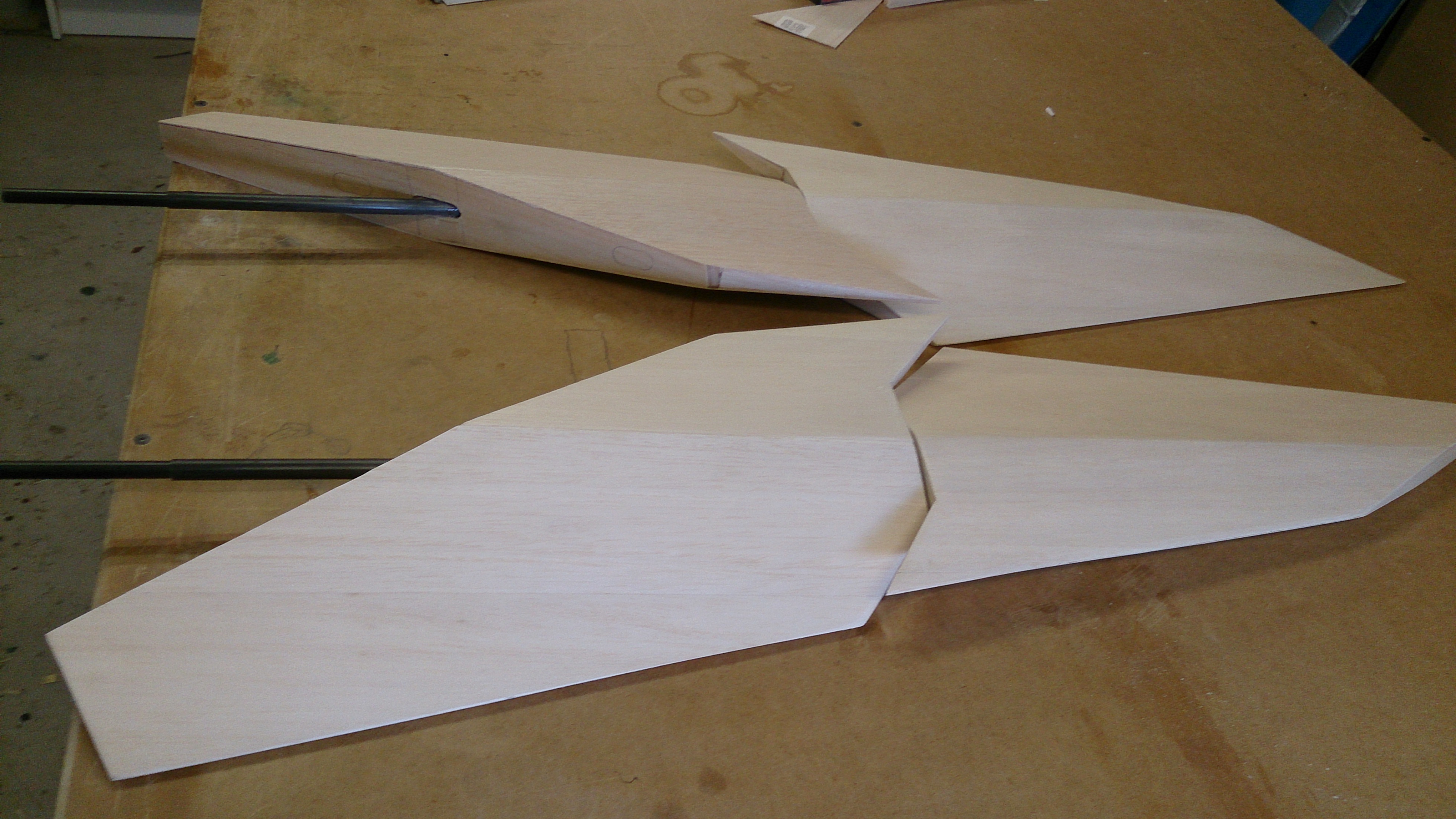
As you can see in the pictures, we glued sheets of 6mm hard balsa to make the spine (the center former) then all sanded flat and keyed up using the Woodpicker tool - great tool, it makes a big enhancement to strength of the sheeting - then on a big 16mm melamine MDF sheets which have been waxed we put epoxy resin then the fiberglass cloth then more resin, then the balsa, more resin, then fiberglass and one more layer of resin then the top melamine MDF sheet then a lot of wight on top of the whole thing.
After 24 hours, the result was very strong and light sheet of fiberglased balsa. We cut out the spine from it and we were surprised the weight.
The spine is 2.2m long and 300mm at the highest point and 6mm thick, the weight is 530g only... so happy with that.
Next we will make more 6mm sheets for the rest of the formers and 3mm for the mezzanine (the horizontal sheets which will attach to each side of the spine and where everything will attached to) and 1.5mm sheets for all the outside skin which will be laid on glass sheets to - hopefully - get very smooth surface ready for painting with minimal preparation (we will start testing on that next weekend).
With this material I think we'll be able to achieve the weight we want.
Talk to you soon guys.


Thank you all for your feedback and ideas about the material.
We have done a some testing with different options and the best combination of wight and strength was for Balsa and fiberglass.
So sheets of balsa (3mm and 6mm) with 100gsm fiberglass on both sides came out very strong and light.
As you can see in the pictures, we glued sheets of 6mm hard balsa to make the spine (the center former) then all sanded flat and keyed up using the Woodpicker tool - great tool, it makes a big enhancement to strength of the sheeting - then on a big 16mm melamine MDF sheets which have been waxed we put epoxy resin then the fiberglass cloth then more resin, then the balsa, more resin, then fiberglass and one more layer of resin then the top melamine MDF sheet then a lot of wight on top of the whole thing.
After 24 hours, the result was very strong and light sheet of fiberglased balsa. We cut out the spine from it and we were surprised the weight.
The spine is 2.2m long and 300mm at the highest point and 6mm thick, the weight is 530g only... so happy with that.
Next we will make more 6mm sheets for the rest of the formers and 3mm for the mezzanine (the horizontal sheets which will attach to each side of the spine and where everything will attached to) and 1.5mm sheets for all the outside skin which will be laid on glass sheets to - hopefully - get very smooth surface ready for painting with minimal preparation (we will start testing on that next weekend).
With this material I think we'll be able to achieve the weight we want.
Talk to you soon guys.
04-11-2015, 04:57 AM
#30
Member
Thread Starter
Join Date: Sep 2005
Location: Perth, AUSTRALIA
Posts: 55
Likes: 0
Received 0 Likes
on
0 Posts
Hi all
It have been a while since our last post, but we did quite a bit of progress on the project.
We are a more ahead of what in the attached pics, but I didn't take pictures of our final progress yet. (may be tomorrow).
I don't think I need to talk much, the pictures will say more.


Looking forward for your feedback guys.
Cheers
Moatasem
It have been a while since our last post, but we did quite a bit of progress on the project.
We are a more ahead of what in the attached pics, but I didn't take pictures of our final progress yet. (may be tomorrow).
I don't think I need to talk much, the pictures will say more.
Looking forward for your feedback guys.
Cheers
Moatasem
04-11-2015, 02:31 PM
#32
Member
Thread Starter
Join Date: Sep 2005
Location: Perth, AUSTRALIA
Posts: 55
Likes: 0
Received 0 Likes
on
0 Posts
Thank you dude.
Yes all the tanks are removable, but to remove the front tanks I'll have to remove the back once first.
It is a big plane but very limited in the internal area, because of the position of the CG.
Regards
Moatasem
06-14-2015, 04:44 PM
#34

Join Date: Nov 2003
Location: Curitiba, Parana, BRAZIL
Posts: 4,289
Likes: 0
Received 14 Likes
on
11 Posts
Looking great, the pipes also look fantastic.
If you want a feedback my only one would be asking about removable landing gear plates for manutention ease., cant be sure in the pics if the CF reinforcements are those already.
If you want a feedback my only one would be asking about removable landing gear plates for manutention ease., cant be sure in the pics if the CF reinforcements are those already.
06-14-2015, 06:18 PM
#35
Member
Thread Starter
Join Date: Sep 2005
Location: Perth, AUSTRALIA
Posts: 55
Likes: 0
Received 0 Likes
on
0 Posts
Thank you for your feedback, but the CF plates are not removable. but the mounting area is going to be reinforced a lot more.
There is no much room to work in this area so I've to make it a strong as I possible..
 06-29-2015, 05:04 PM
#37
Member
Thread Starter
Join Date: Sep 2005
Location: Perth, AUSTRALIA
Posts: 55
Likes: 0
Received 0 Likes
on
0 Posts
Hi All
Some more progress....
I'm thinking of buying to 2 new engines, my plan was to use the 2 Simjets 2300 that I already have but to have more confident and reliability and to save some weight (around 1.5kg) I think I'll go for 2 new Jet Munts M100XBL.
That plow a big hole in my budget but I think it worth it.... any thoughts?
some pics from the last work...


Regards
Moatasem
Some more progress....
I'm thinking of buying to 2 new engines, my plan was to use the 2 Simjets 2300 that I already have but to have more confident and reliability and to save some weight (around 1.5kg) I think I'll go for 2 new Jet Munts M100XBL.
That plow a big hole in my budget but I think it worth it.... any thoughts?
some pics from the last work...
Regards
Moatasem
Last edited by Migf117; 06-29-2015 at 05:08 PM.
06-29-2015, 05:05 PM
#38
Member
Thread Starter
Join Date: Sep 2005
Location: Perth, AUSTRALIA
Posts: 55
Likes: 0
Received 0 Likes
on
0 Posts
Hi All
Some more progress....
I'm thinking of buying to 2 new engines, my plan was to use the 2 Simjets 2300 that I already have but to have more confident and reliability and to save some weight (around 1.5kg) I think I'll go for 2 new Jet Munts M100XBL.
That plow a big hole in my budget but I think it worth it.... any thoughts?
some pics from the last work...
Regards
Moatasem
Last edited by Migf117; 06-29-2015 at 05:08 PM.
06-29-2015, 05:42 PM
#39
Join Date: Nov 2003
Location: Curitiba, Parana, BRAZIL
Posts: 4,289
Likes: 0
Received 14 Likes
on
11 Posts
Whatever brand you choose the most important reliability you can add to the project is making the thrust lines not paralel to the centerline, but pointing as much as you can to the center of pressure of the plane.. (somewhere near the cabin) . This will cancel out the yaw in case of one engine quitting and avoid a potential loose of control.
06-29-2015, 06:38 PM
#40
Member
Thread Starter
Join Date: Sep 2005
Location: Perth, AUSTRALIA
Posts: 55
Likes: 0
Received 0 Likes
on
0 Posts
Whatever brand you choose the most important reliability you can add to the project is making the thrust lines not paralel to the centerline, but pointing as much as you can to the center of pressure of the plane.. (somewhere near the cabin) . This will cancel out the yaw in case of one engine quitting and avoid a potential loose of control.
The engines and the exhaust pipes are at the closest location to the centerline. at the front I've the tanks between the engines and at the back I've the ruders.
Hopefully the current location of them will not cause much of yaw effect in case of a flame out.
07-29-2015, 04:11 PM
#41
Member
Thread Starter
Join Date: Sep 2005
Location: Perth, AUSTRALIA
Posts: 55
Likes: 0
Received 0 Likes
on
0 Posts
Hi Guys
A little bit more work done.
I didn't do much work on the plane itself as I was busy building a spot welder because I need to make my own pipes.
The pipes I got are great but there is a wrong angle on them which I can't fix.. errrrrrrrrrr.
So with the great help from Phil Celima from Jet Products Australia, I got the right material and got the spot welder working.
We bought 2 new JetMunt MX100 and Electron Retracts Evo40e from Jet Products Australia too.. Best service ever.
Now to some pics of the latest work and a video of the door mechanism testing.
https://youtu.be/iqeiaz4ttFc
08-12-2015, 12:29 AM
#43
My Feedback: (2)
Join Date: Jul 2003
Location: Brisbane, QLD, AUSTRALIA
Posts: 2,787
Likes: 0
Received 8 Likes
on
4 Posts
Nice piece of fabrication there!!
Are those door collars 3D printed?
The Jetmunt engines are great! I have had 6 flights with my 140XBL and just love it.
It's a shame that you don't see more F-117's getting around, such a different shape in the sky.
Thanks
dave
Are those door collars 3D printed?
The Jetmunt engines are great! I have had 6 flights with my 140XBL and just love it.
It's a shame that you don't see more F-117's getting around, such a different shape in the sky.
Thanks
dave
08-12-2015, 02:36 AM
#44
Member
Thread Starter
Join Date: Sep 2005
Location: Perth, AUSTRALIA
Posts: 55
Likes: 0
Received 0 Likes
on
0 Posts
Thank you for your comment..
Yes, the door collars are 3D printed and some other pieces as well.
I'm looking forward for the 2 new engines, they should be great.
Regards
Moatasem
08-17-2015, 06:52 PM
#45
Member
Thread Starter
Join Date: Sep 2005
Location: Perth, AUSTRALIA
Posts: 55
Likes: 0
Received 0 Likes
on
0 Posts
Hi evey one
We've finished both pipes.
Each is around 650g with 90mm square intake, 210x40mm outlet and 830mm length.
We'll make a carbon fiber bell mouth, I've designed the plug and I'll 3D print it.
Not sure if we need the bell mouth, any ideas?


We've finished both pipes.
Each is around 650g with 90mm square intake, 210x40mm outlet and 830mm length.
We'll make a carbon fiber bell mouth, I've designed the plug and I'll 3D print it.
Not sure if we need the bell mouth, any ideas?
08-17-2015, 11:25 PM
#46
Join Date: Jul 2006
Location: Norfolk , UNITED KINGDOM
Posts: 1,409
Likes: 0
Received 0 Likes
on
0 Posts
This is a great project and well done so far. If I was making the pipes I would transition the squares into rounds gradually and insert a round collar and then a standard bell mouth like the ones from Grumania. They can be spun from soft aluminium. A lot of air gets drawn down the pipe around the back of the turbine and I would always fit an intake bell mouth. If pipes end in a straight end without a bell mouth they will usually have a bypass which is effectively a bell mouth. Not sure how this would work out in your installation though.
What do you reckon the finished weight will be? the pipes will take a bit of counterbalancing?
John
What do you reckon the finished weight will be? the pipes will take a bit of counterbalancing?
John
08-21-2015, 11:25 PM
#47
Member
Thread Starter
Join Date: Sep 2005
Location: Perth, AUSTRALIA
Posts: 55
Likes: 0
Received 0 Likes
on
0 Posts
Hi John
Thank you for your comments.
I would've been so hard to make the pipes square at the outlet and round at the inlet - at least for me - as we don't have experience in metal fabrication.
I think the square pipes will do the job with the carbon fibre bell mouth which I'll make, I've a carbon fibre bell mouth on one of jets and it is fine after over 100 flights.
This plane will be very tail heavy and will require a lot of nose weight anyway even with all the batteries and electronics as forward as possible and with the engines just in front of the CG, so some counter weight for the pipes will not be an issue.
Regards
Moatasem
08-22-2015, 12:14 AM
#48
Join Date: Jul 2006
Location: Norfolk , UNITED KINGDOM
Posts: 1,409
Likes: 0
Received 0 Likes
on
0 Posts
Hi John
Thank you for your comments.
I would've been so hard to make the pipes square at the outlet and round at the inlet - at least for me - as we don't have experience in metal fabrication.
I think the square pipes will do the job with the carbon fibre bell mouth which I'll make, I've a carbon fibre bell mouth on one of jets and it is fine after over 100 flights.
This plane will be very tail heavy and will require a lot of nose weight anyway even with all the batteries and electronics as forward as possible and with the engines just in front of the CG, so some counter weight for the pipes will not be an issue.
Regards
Moatasem
Thank you for your comments.
I would've been so hard to make the pipes square at the outlet and round at the inlet - at least for me - as we don't have experience in metal fabrication.
I think the square pipes will do the job with the carbon fibre bell mouth which I'll make, I've a carbon fibre bell mouth on one of jets and it is fine after over 100 flights.
This plane will be very tail heavy and will require a lot of nose weight anyway even with all the batteries and electronics as forward as possible and with the engines just in front of the CG, so some counter weight for the pipes will not be an issue.
Regards
Moatasem
Moatasem
I am sure your intake bell mount will work fine, it is so nice to see a scratch built plane it just enthuses me to build more!
Having built several turbine powered jet flying wings I well understand they usually need lead with the wing area being behind CG and a short nose. It is so annoying to add lead all modellers hate it.
John
11-22-2015, 05:04 PM
#49
Member
Thread Starter
Join Date: Sep 2005
Location: Perth, AUSTRALIA
Posts: 55
Likes: 0
Received 0 Likes
on
0 Posts
Hi Everyone
It have been a while since my last post but I have been very busy between work and life.
I've finished a long going project over couple of weeks. Finishing the Zero.
It is an ESM kit 90" powered by 80cc MVVS engine, sliding canopy, full detailed cockpit (not ready, we've built it from plastic parts) and all internal controls on all the surfaces (RDS).
It came out good I think.
Now back to the F117, we've done a lot of work on it as well, finishing the rudders, engine mounts and a lot more.
We did a test run of the engines to confirm that there is no leak on the pipes and the heat around them will not burn the wood.
All the area around the pipes and engines is painted with BVM Heat Shield, very good stuff and works very well.
While the engines are running I can put my hand on the outer piper, the heat doesn't' even travel 15mm from the inner pipe and that is without any air flow around pipes. Very happy with that.
The fuselage with wings and rudders is 8.2kg, I think we are on right direction to get to the target weight of 20-22kg dry.
Some pictures to show the progress and couple of pics for the Zero too.
Regards
Moatasem
