


Skymaster Avanti XXL Build Thread


 11-14-2014, 07:19 AM
#28

Thread Starter

So it looks like 110mm for K210 Class turbine and My thrust pipe is 125mm for Mammoth size pipe.
So I did some clean up on the tank mod and I decided to give the gear doors a nice coat of black paint, they had paint on them from the factory on the inside and just didnt look professional to me.
I also add two small brass tube pieces to each gear to hold the brake line in place, I hate zip ties on gear struts. Just a personal thing, I will also not be using zips on my wires anymore I have a great solution for this and its much better and as small as it is will save weight.
Last edited by FenderBean; 11-14-2014 at 07:23 AM.
11-14-2014, 07:50 AM
#29
My Feedback: (1)
Join Date: Jul 2002
Location: SevenoaksKent, UNITED KINGDOM
Posts: 5,193
Likes: 0
Received 0 Likes
on
0 Posts
Let me know how you get on installing the horns. The supplied horns are short with hardly any rake on them. You can't get the pivot point over the hinge rod as the support block appears to be set further back in the surface. I had to 'lean' mine forward as best I can. Not ideal but not gonna make a huge difference so long as both sides are in the same position.
Will post pics etc of mine over the weekend
Will post pics etc of mine over the weekend
11-14-2014, 10:31 AM
#30
Thread Starter
i noticed my blocks they added after the jet was built are to far back as well. They do the same thing as all the other guys they just dont pay attention to the details sometimes. I may use different control horns on mine, the problem is i got an email from dreamworks and they are out of futaba arms i need. They sent one futaba and 4 JRs and im not going to start cutting until i can get all the arms on and attach the control rods. The good thing is the pivot points of the control surfaces are back so well see.
This project is playing hard to get, killing the motivation.
This project is playing hard to get, killing the motivation.
11-14-2014, 08:14 PM
#32
Thread Starter
Helijet, I noticed I have two main tanks and one smoke tank, did yours not come with three tanks?
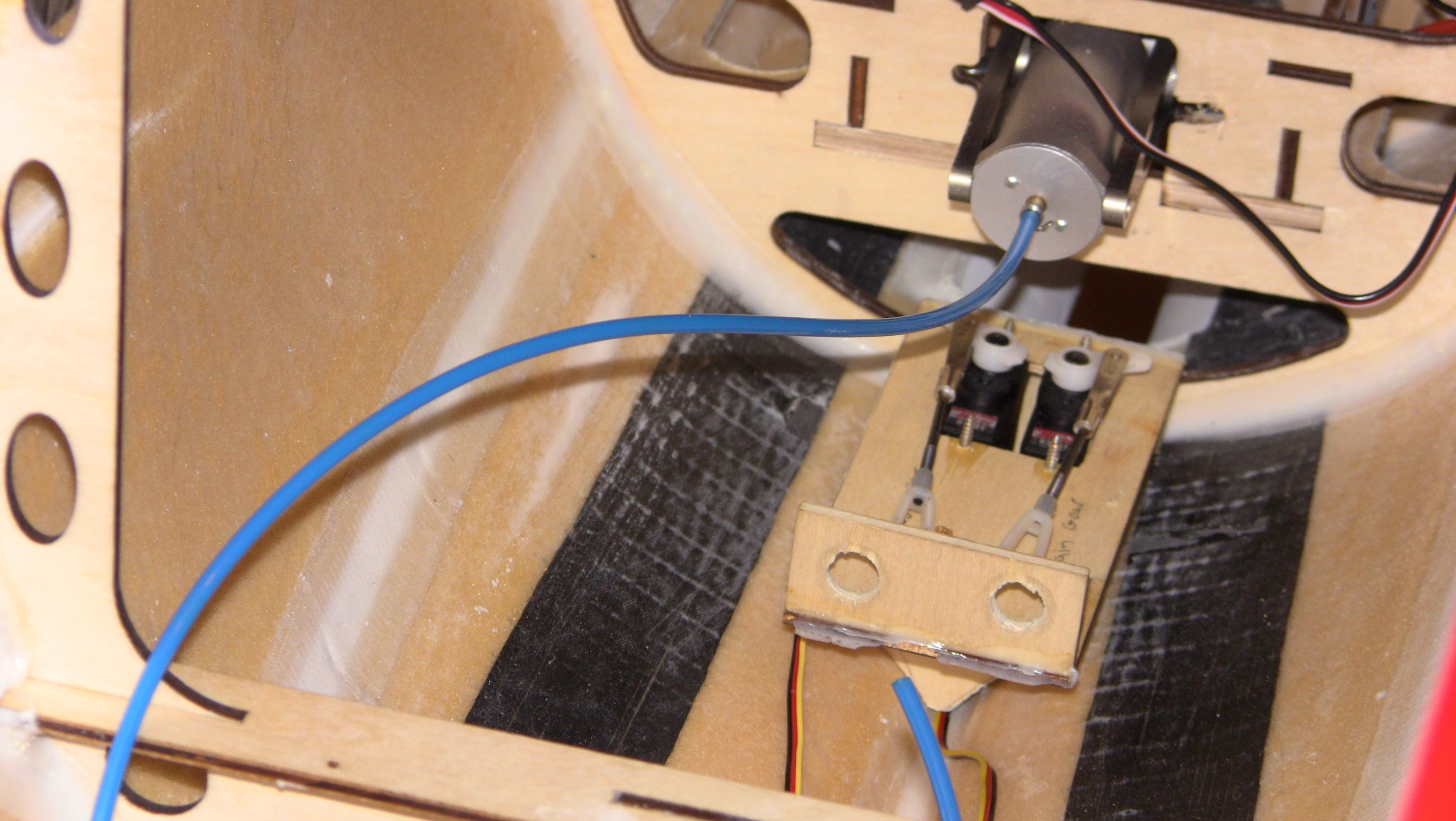
Before heading out tonight I managed to get the servos for the elevators in they face in towards the tip of stab. Nothing major just a simple four screw setup to hold them in and I made some ply mounts for the nose gear servos as well and will glue them on next
 .
.


New Video is uploading on my Youtube page
Before heading out tonight I managed to get the servos for the elevators in they face in towards the tip of stab. Nothing major just a simple four screw setup to hold them in and I made some ply mounts for the nose gear servos as well and will glue them on next
New Video is uploading on my Youtube page
Last edited by FenderBean; 11-14-2014 at 08:17 PM.
11-14-2014, 09:23 PM
#33
Correct..only 2. I have not measured the capacity but I suspect that the large tank I have is for fuel at 5.2 L. The smaller is 2 litres for smoke. You have an extra 2.5 litres for the larger engine displacement which would make sense as you have the larger thrust tube?
Dean
Dean
11-14-2014, 10:40 PM
#34
Thread Starter
I thought the larger pipe and extra tank was only for the BF300 setup, that being said the BF300 is about the same in fuel usage. Thanks for the info, after seeing how tail heavy the thing is I will be putting in some boards further into the nose over the nose wheel to help balance things out.
Correct..only 2. I have not measured the capacity but I suspect that the large tank I have is for fuel at 5.2 L. The smaller is 2 litres for smoke. You have an extra 2.5 litres for the larger engine displacement which would make sense as you have the larger thrust tube?
Dean
Dean
11-15-2014, 03:36 PM
#35
Thread Starter
Well back at it after, started on installing the fuselage stuff today, I am moving my power system further up the nose closer to the battery tray. This jet normally comes out tail heavy and to prevent adding weight I am moving stuff as far forward as possible. I made a mount and laminated it with carbon fiber to increase the strength, I could have used thicker ply but I have some materials I need to use up before they go bad. Plus its just more fun  !
!
While that is setting up I moved on to the nose gear door servo mounting, both are in place and cured. Before taking a break I started marking the layout on the base board I will be using and getting ready to mount things.
I put another video up on my youtube site should a few things! Roll Tide!


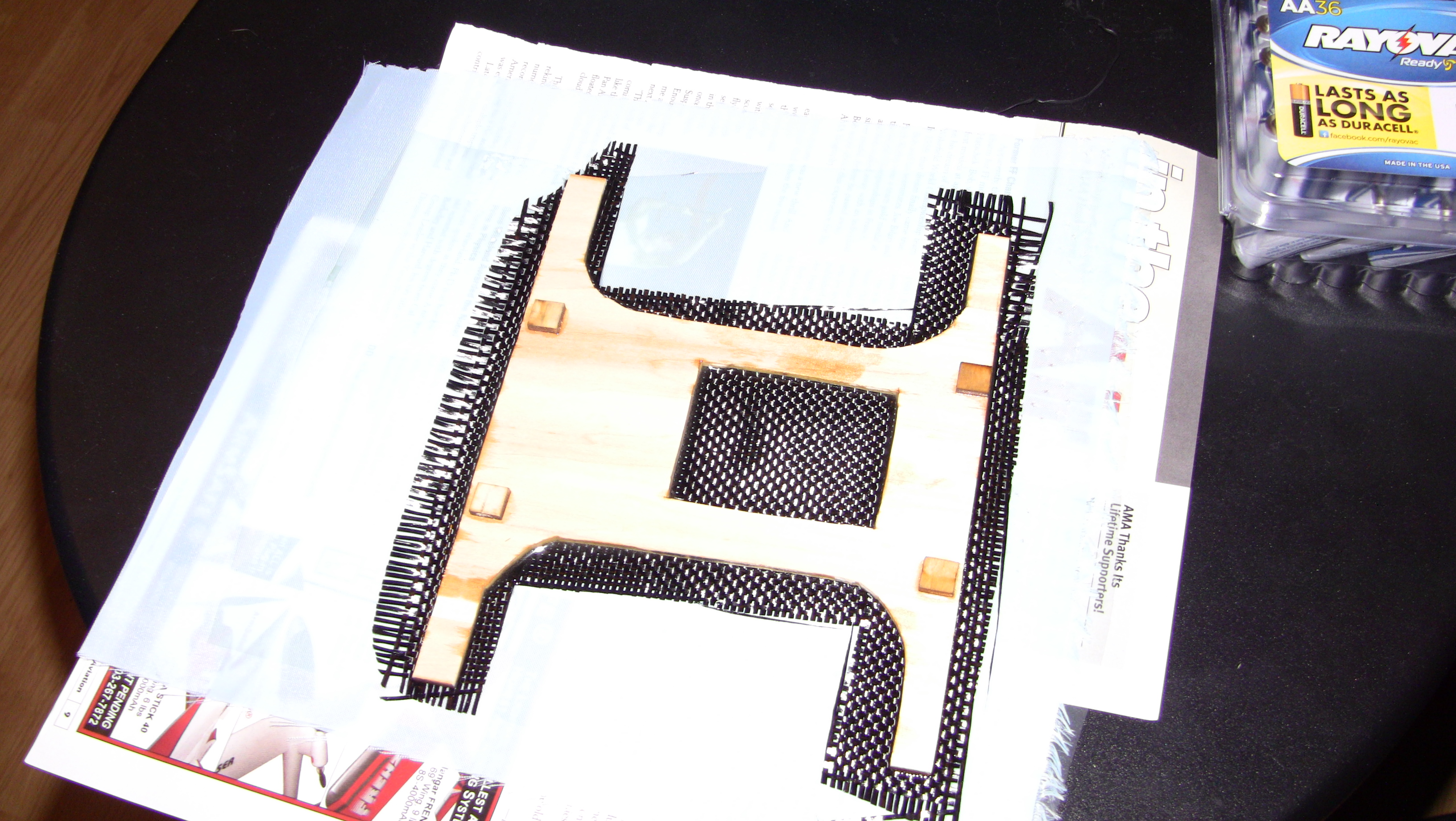


!While that is setting up I moved on to the nose gear door servo mounting, both are in place and cured. Before taking a break I started marking the layout on the base board I will be using and getting ready to mount things.
I put another video up on my youtube site should a few things! Roll Tide!
11-15-2014, 08:27 PM
#38
Thread Starter
 11-15-2014, 08:44 PM
#39
Thread Starter
Well been busy tonight working on getting the equipment in for the air stuff. I made some mounts for my robart two-way valves and my UP6 brake valve. They will be under my base board so it will have a nice clean look once everything is in. The mount for the Robbe/Futaba battery backer will be ready in the morning so I will finish up the power system then and get the servo wires ran and al the valves hooked up. I went ahead and rough cut the holes for the brake/gear air lines, I think the a three line flush type would have been real easy to install on this jet.
Not sure how much more I will get tonight since the resign is still setting up but I do have another video uploading.


Not sure how much more I will get tonight since the resign is still setting up but I do have another video uploading.
Last edited by FenderBean; 11-15-2014 at 08:47 PM.
11-16-2014, 12:27 AM
#40
Thread Starter
Well, I remember why I hate air systems, the dang airlines are still a pain even the few I had to do on this one. I glued in some small hose clips to keep the lines in place and I use 4 disconnects on the a few areas to allow for the base board to be remove and disconnected from the fill ports and brake lines. I will finish up the mounting of electronics tomorrow and after that its just add the fuel system. Then I have to wait on the servo arms and turbine stuff to do the pipe.


11-16-2014, 08:44 AM
#41

How much ATV are you going to need to use with such long servo arms?
Okay so the corrected servo box issue is curing and the servos are mounted via your typical "L" bracket with screws and washers.
I have to get longer servo Arms, looks like 1.5 inch arm will work for everything, the flaps and Rudder need the longest arms. You could even use a 2 inch on the flaps and rudder, but i going 1.5 if I have to cut more area for the arms I will.


I have to get longer servo Arms, looks like 1.5 inch arm will work for everything, the flaps and Rudder need the longest arms. You could even use a 2 inch on the flaps and rudder, but i going 1.5 if I have to cut more area for the arms I will.
11-16-2014, 09:06 AM
#42
Thread Starter
I'm Not Sure Until I Get Everything Hooked Up. Based On Th Throws In The Book And Considering It's A 3d Jet I Will Prob Want Need Much. I Do Have The Ability To Move Down On The Servo Arm For The Aileron. I Normally Don't Lower In Points Much To Prevent Losing Resolution. Sorry For All The Capitol Letters For Some Reason When I Use My Phone On Rcu It Does This.
11-16-2014, 03:51 PM
#43
Thread Starter
Well all the electronics are in and all the air system is in as well. That leaves the fuel system, turbine and pipe to install, oh and the control arms once the correct futaba SWB arms ship from dreamworksrc. I really like how my carbon mount turned out for the battery backer, gives a nice strong mount and plenty of work around space. I made some mounts to support the mount and used hysol to glue it in, the mounts are to help with landing jolts. I added my two receivers to each side of the jet and made 4 antenna holders out of a plastic tube, fuel tubing and foam tube holder. I use this type of holder on my helis it has been a very simple effective method so I use it on everything. The only thing I need to mount is the Robbe GPS sensor, I forgot about it until today. I will use this until I can get a Igyro/gps senor down the road.


Two new videos are uploading. It may be slow going for few days till I get the items I need
Two new videos are uploading. It may be slow going for few days till I get the items I need
Last edited by FenderBean; 11-16-2014 at 03:59 PM.
11-17-2014, 10:28 PM
#44
I have found that there is quite a bit of play in the hinge pins, especially the ailerons and flaps. The holes in the hinge plates are a bit big for the wire hinge pin. Once you have hooked up the servos, pushrods etc. the movement in the surfaces (up and down) is pretty bad. I need to think of a way to bush the hinge where the wire pins go through to sort this out.
Last edited by In the Haze; 11-18-2014 at 01:28 AM.
11-20-2014, 07:05 PM
#45
Thread Starter
FINALLY The servo arms arrive!!! LOL well now I can get back to some building. Its been a good day, started out rough being very tired this morning morning and riding 7.2 miles and working all day but it ended good. Got three boxes of stuff and I found out my F-14 is out of paint!!!!So the count begins.
Anyway build related my Gear fail safe/ sequencer isnt working right and will be going back to dreamworks for a checkout but while I wait on that I will be adding two small nickel size air gauges and continuing with the build. I installed the last flap servo and cut the slot for the arm and will be moving on to the elevators and rudders next.
Two cutting action videos uploading on my channel

 Please not the new shop tool! Thanks Paul but my wife is taking the rest but I managed to grab a few
Okay so moving on to the elevators and I am going to trim the 2in swb arm down about 1/2 in the stabs are much thinner than the rudder and wings. I am doing this to prevent cutting a servo arm open longer than it needs to be. Plus if I cut this channel it would get in to area that I dont want to cut.
So just to clarify the aileron arms need to be at least an 1 inch, flaps 2 inch, rudder 1.5-2 inch and elevator probably could get away with 1 inch but i recommend 1.5 in nose steering was 1 inch
Wings are ready to cut and glue the control horns in but im stopping for the night, im just tired. The Army is tough on the joints after 15 years. Cheers!
Anyway build related my Gear fail safe/ sequencer isnt working right and will be going back to dreamworks for a checkout but while I wait on that I will be adding two small nickel size air gauges and continuing with the build. I installed the last flap servo and cut the slot for the arm and will be moving on to the elevators and rudders next.
Two cutting action videos uploading on my channel
Okay so moving on to the elevators and I am going to trim the 2in swb arm down about 1/2 in the stabs are much thinner than the rudder and wings. I am doing this to prevent cutting a servo arm open longer than it needs to be. Plus if I cut this channel it would get in to area that I dont want to cut.
So just to clarify the aileron arms need to be at least an 1 inch, flaps 2 inch, rudder 1.5-2 inch and elevator probably could get away with 1 inch but i recommend 1.5 in nose steering was 1 inch
Wings are ready to cut and glue the control horns in but im stopping for the night, im just tired. The Army is tough on the joints after 15 years. Cheers!
Last edited by FenderBean; 11-20-2014 at 08:58 PM.
11-20-2014, 09:01 PM
#46
Thread Starter
I also forgot to mention that all the control surfaces have a rod slid through that can be pulled out to remove the surfaces. No sure how I like this yet I guess well see over time how it holds up, mine are all tight for sure no slop so far!
11-21-2014, 08:14 PM
#47
Thread Starter
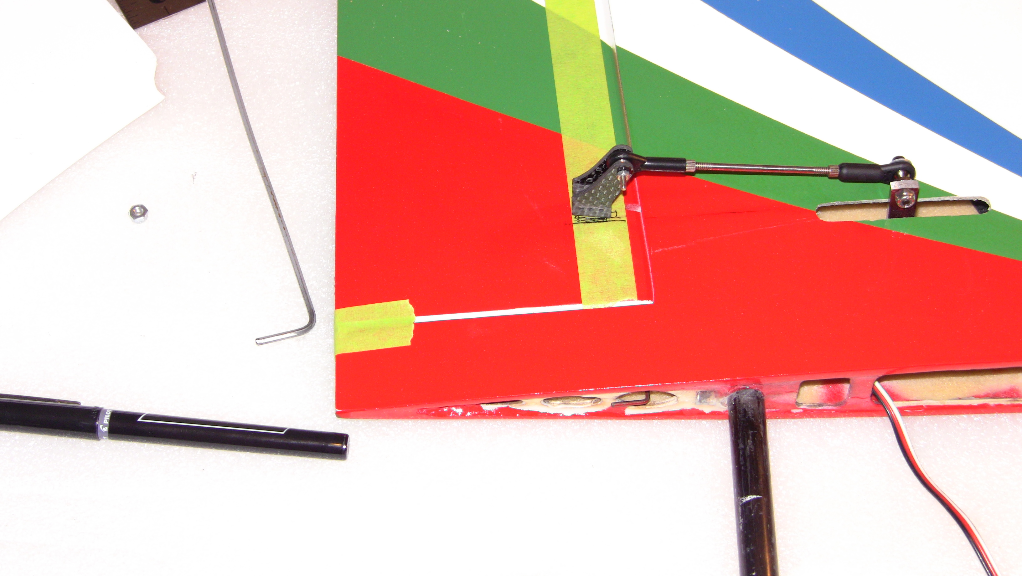
Slow going tonight, dad time was taking priority but I did manage to get the pivot points taped on the control surfaces. This was done by removing the surface and using the pin as a guide, after this I marked the control horn slots. Next thing is to cut the slots, align the control horn with the pivot point and hysol them in. I am uploading a video explaining the same things here, plus some off topic stuff so check out my channel for that. I found a nice little product to replace those nasty zip ties  so I will be using it from now on instead. Tomorrow will be more productive I hope after this not much else to do until a turbine shows up
https://www.youtube.com/channel/UCE_...BAxA8bHVCw3VQQ
.


Some may be wondering what the electronics are for

so I will be using it from now on instead. Tomorrow will be more productive I hope after this not much else to do until a turbine shows uphttps://www.youtube.com/channel/UCE_...BAxA8bHVCw3VQQ
.
Some may be wondering what the electronics are for
Last edited by FenderBean; 11-21-2014 at 08:21 PM.
11-22-2014, 01:43 PM
#49
Thread Starter
Okay after much effort the control horns are cut, what a pain in the butt! SM needs to do a better job about block placement for the control horns period. I do have wood to hold to in everything except the ailerons so I will add some epoxy soaked sponge to hold it. What I didnt think about and you have to be careful about is the plastic tube inside the control surface the pin is guided threw. SM put the control horn location inline with a pivot point that just bad mojo so it requires care in cutting a glue placement our you will mess something up.
Vidoe is uploading that describes this stuff, im going to get some sponge cut and epoxy mixed up. After this not much I can do but mount the tanks and wait for a turbine.


Vidoe is uploading that describes this stuff, im going to get some sponge cut and epoxy mixed up. After this not much I can do but mount the tanks and wait for a turbine.
11-22-2014, 06:09 PM
#50
Thread Starter
Okay I have all the control horns semi glued in and im taking a break before I start throwing stuff at the walls LOL After getting the hinges in I really think the ones they supplied with the kit are to small. Longer horns are going to be a recommendation for skymaster on this kit, no way possible to get the horns down to the bottom skin like I like them to be. Beer time and some couch time with the miss!


Last edited by FenderBean; 11-22-2014 at 09:57 PM.