


New JR 3 Axis Aeroplane Gyro
 11-18-2014, 07:58 AM
#1

Thread Starter
JR about to release this into the fold of many gyros suitable for our craft.
With work with JR Xbus or even Futaba S Bus
With work with JR Xbus or even Futaba S Bus
 11-18-2014, 09:52 AM
#4

Nice neat compact unit.
Is it to be used between an Rx and its servos only ? "very good"
Or much more useful, can it be used with just X-Bus input as a PWM interface expanding say the 7ch Rx by a possible 6ch,s in which case its "brilliant" .
.
Is it to be used between an Rx and its servos only ? "very good"
Or much more useful, can it be used with just X-Bus input as a PWM interface expanding say the 7ch Rx by a possible 6ch,s in which case its "brilliant"
.
 11-18-2014, 12:02 PM
#6
I just spent an hour or so this afternoon reading the manual for this new JR X-Bus Gyro, It can not be used as a loop in loop out PWM type gyro, my mistake.
Check out the user manual for your selves here
http://www.jrpropo.co.jp/english/dl/....php?hen=d0385
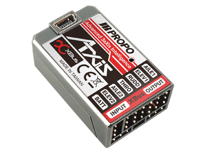
The most straight forward option is to use the RG731BX 7ch rx (you will lose its 7 PWM outputs) and connect up the Gyro via its X-Bus output.
This will allow you to use the 6ch PWM outputs on the gyro instead, this explains why there is a throttle output on the gyro
.This is OK for very simple airframes only requiring the 6 chs.
It would seem if you want to use more than 6ch this is the least you will need to do
For S or X-Bus Servos
Connect via X-bus to the gyro from an X-Bus Rx then from the gyro take its X-Bus output (consequently now loosing its 6x PWM outputs) to a X-Bus hub.
From there you can plug in up to 4x NX (JRs S-Bus) servos, or 3 NX Servos and its now empty 4th output on to another Hub giving 4 more NX outputs, or 3 NX servos + another hub and so on and so on, I think the limit with my XG14 was up to 56 X-Bus servos.This was achieved by having up to 14 gangs of 4 servos, each gang controlled as one ch but all 4 of that gang can be individually adjustable for end, sub, direction and travel .
Or for PWM Servos
Once the gyro is connected to a X-Bus capable Rx, from the X-Bus out on the gyro or any expander hubs in turn connected to it you can connect 1,2 or 4 way PWM converters, each giving you 1,2-4 servos for each converter.
So 1x Rx + 1x Gyro +1x Hub + up to 4x 4 way PMW converters = up to 16 PMW servos.
The RG731BX 7ch Rx gives a "simple" single Rx setup (you do lose its 7 PWM outputs), If you want better aerial diversity there are options like the RG031BX with its simple hub and 3x sats (no PWM outputs).
JR DMSS is a good system with a good solid RF link but I'm not totally convinced about the practicality of JRs X-Bus though , It seems to get more involved at every turn, when I tried an X-Bus setup on the bench last year it worked OK but had a high component count and did look a bit of a dogs dinner
") .
.
Last edited by Mark Vandervelden; 11-18-2014 at 03:49 PM.

 11-18-2014, 06:34 PM
#9
Hi
I cant find a manual for the XB1-14DRS yet but a common feature of JR DMSS RXs so far is you get PWM or X-Bus output "not" both. If indeed you cant have both with this 14ch Rx when you try to use the gyro with this Rx it will become a 6ch setup and end up with dead PMW outputs and having to fit hubs. If that's the case you would be better off with the RG031BX . I hope JR have resolved this but I would ask first to avoid disappointment.
I cant find a manual for the XB1-14DRS yet but a common feature of JR DMSS RXs so far is you get PWM or X-Bus output "not" both. If indeed you cant have both with this 14ch Rx when you try to use the gyro with this Rx it will become a 6ch setup and end up with dead PMW outputs and having to fit hubs. If that's the case you would be better off with the RG031BX . I hope JR have resolved this but I would ask first to avoid disappointment.
11-19-2014, 12:22 AM
#10
Thread Starter
11-19-2014, 04:44 AM
#12

If you use a RG731BX receiver and you put it in XBus mode A as shown in the Gyro's users manual page 23 you will NOT loose the normal PWM outputs from the receiver. Only if you switch the receiver into XBus mode B you will loose the PWM outputs from the receiver !?!.
I decode the JR XBus protocol in my ASSI devices and I use Mode A for this and the servos on the PWM outputs on the receiver are still working (TX is a XG14)
I decode the JR XBus protocol in my ASSI devices and I use Mode A for this and the servos on the PWM outputs on the receiver are still working (TX is a XG14)
11-19-2014, 05:05 AM
#13

My Feedback: (57)
If you use a RG731BX receiver and you put it in XBus mode A as shown in the Gyro's users manual page 23 you will NOT loose the normal PWM outputs from the receiver. Only if you switch the receiver into XBus mode B you will loose the PWM outputs from the receiver !?!.
I decode the JR XBus protocol in my ASSI devices and I use Mode A for this and the servos on the PWM outputs on the receiver are still working (TX is a XG14)
I decode the JR XBus protocol in my ASSI devices and I use Mode A for this and the servos on the PWM outputs on the receiver are still working (TX is a XG14)
Why does it have a Mode A & B? What would be the reason/advantage of "disabling" PWM?
11-19-2014, 05:16 AM
#14
Good question George
Mode A has the ability also to handle telemetry etc (basically bi-directional)
Mode B is the "old mode" as I understand it. It is a one-way communication protocol (which uses the (almost) same protocol as other radios.
When configured to Mode B the PWM outputs are disabled on the receiver, why it is so, I have no clue !!
In Mode A all the PWM outputs continue to function
I'm by NO means a "JR XBus" expert, I have just seen this behavior as I'm designing add-on equipment for our jets and needed to be able to use both Futaba SBUS2 and JR XBus system
(so take what I write with a grain of salt )
)
Mode A has the ability also to handle telemetry etc (basically bi-directional)
Mode B is the "old mode" as I understand it. It is a one-way communication protocol (which uses the (almost) same protocol as other radios.
When configured to Mode B the PWM outputs are disabled on the receiver, why it is so, I have no clue !!
In Mode A all the PWM outputs continue to function
I'm by NO means a "JR XBus" expert, I have just seen this behavior as I'm designing add-on equipment for our jets and needed to be able to use both Futaba SBUS2 and JR XBus system
(so take what I write with a grain of salt
)
11-19-2014, 08:35 AM
#16
Hi Carston
I know from past experience of actual use that when using the JR RG731BX with the XG14 in mode "A" as is required to operate this new X-Bus gyro I defiantly did not get active PWM outputs from the RXs outputs. I used two of these DMSS X-Bus RXs a wile back with Powerbox SRS eqipment, both the I-Gyro and Competition, they also requires JRs type "A" X-Bus and no PMW outputs were avialabe, I had a long period of emailing back and forth with the UK JR rep and Richard at Powerbox about this lack of PWM outputs and also about the conflicts you get when using JR telemetry and multiple sats or RXs. All party's were very helpful as I believe I was the first to use these setups out in the field but as far as I'm aware nothing has changed fundamentally since then.
"Carston" How do you get the PWM and X-Bus outputs to work on the 7ch X-Bus Rx at the same time? It would be very helpful if they did and make the X-Bus system far more practical.
Type "B" X-Bus was a result of makeing JR X-Bus compatible with Freakware, Beast X and Mikado V-Bar flybarless Gyro Systems and is similar to Jeti UDI, Multiplex and Futaba. If you look at the XG 14 Tx manuel page 92, there it states there will only be 12ch available and no PWM outputs from the RX in that mode either, see a section of the relevant page in the XG14 manual below.
MODE.A : This is the JR’s own Original mode it corresponds to the X-Bus servo, Gyro system or able to
allocate Channel ID from the transmitter.
MODE.B : This is serial protocol mode it is corresponds to Freakware, Beast X and Mikado V-Bar flybarless
gyro systems.
Out putting channels are used as follows. Maximum channel is limited to 12channel for this application.
1)
Aileron
2)
Elevator
3)
Rudder
4)
AUX1 ((Pitch/Flap)
5)
Throttle
6)
GEAR
7)
AUX2
8)
AUX3
9)
AUX4
10)
AUX5
11)
AUX6
12)
AUX7
※ Note carefully that there will be “NO” PWM output signals from standard ports at the receiver when X.Bus has
been activated in MODE.B.
Airplane
CAUTION
Glider
System List
Last edited by Mark Vandervelden; 11-19-2014 at 09:03 AM.
11-19-2014, 08:39 AM
#17
Thread Starter
Mark
Everyone.
I'm still learning and understanding Xbus too. My Blanik is the first model I have used Xbus and will probably fit this unit to that for learning how it works.
Dave
Everyone.
I'm still learning and understanding Xbus too. My Blanik is the first model I have used Xbus and will probably fit this unit to that for learning how it works.
Dave
11-19-2014, 09:23 AM
#18
Mark,
yes I'm totally sure that it works this way, select Mode A for XBus and you will have PWM outputs working from the receiver at the same time.
To demonstrate, I just did a quick mock-up of my telemetry stuff I'm working on (sorry for the mess )
)
I connected the RG731 XBus output to my ASSI device, data from that are sent to my ground station (Android phone), on this I have a servo monitor screen (shown in the video). At the same time I have a normal servo connected to the PWM outputs of the receiver. The servo works perfect at the same time as Mode A data are output from the receiver (as is decoded by the ASSI device). You can also see on the video that the receiver is in fact in mode A looking at the transmitter screen. I have also tried moving the servo to the other outputs, same story, they work
PS: The software version of the TX is 0001-0001
The receiver I don't know about...
Sorry for the crappy video quality
https://www.youtube.com/watch?v=9p9eg-lAdIU
yes I'm totally sure that it works this way, select Mode A for XBus and you will have PWM outputs working from the receiver at the same time.
To demonstrate, I just did a quick mock-up of my telemetry stuff I'm working on (sorry for the mess
)I connected the RG731 XBus output to my ASSI device, data from that are sent to my ground station (Android phone), on this I have a servo monitor screen (shown in the video). At the same time I have a normal servo connected to the PWM outputs of the receiver. The servo works perfect at the same time as Mode A data are output from the receiver (as is decoded by the ASSI device). You can also see on the video that the receiver is in fact in mode A looking at the transmitter screen. I have also tried moving the servo to the other outputs, same story, they work
PS: The software version of the TX is 0001-0001
The receiver I don't know about...
Sorry for the crappy video quality
https://www.youtube.com/watch?v=9p9eg-lAdIU
Last edited by Carsten Groen; 11-19-2014 at 09:27 AM.
11-19-2014, 10:21 AM
#19
Hi Carston
My Garst is Flaberd!, something's changed and for the better, new software perhaps, it certainly did not work this way when I bought my XG14 when they were first realised .
I no longer have a XG14 and X-Bus Rx, and this is because at that time exactly this could not be done.
When you have some time and as you have them in front of you can you explore its channel mapping for us. With this new gyro you have as far as I can tell 6ch pre allocated, if you can remap the PWM outputs of the Rx or the Gyro it opens up more practical applications as we may be able to achieve use of the 7+6 channels. I fear 6ch will be duplicated though and hence not of much practical use other than freeing up the 7th channel in the Rx itself but even that would be a bonus. Evan if the channels are duplicated on the 7ch Rx it may be the 8 remaining channels of the XB1-14DRS will be acssssable when connected to the X-Bus gyro
Some interesting gismos you have under development there, can you explain what's ASSI exactly?
11-19-2014, 10:28 AM
#20
My brain officially hurts from reading this. Waiting on futaba to make an Sbus RX that has a three axis gyro integrated… let's go Futaba! I have several planes wired with sbus with either futaba or robbe systems. Hard to go back to running servo wire everywhere.
11-19-2014, 10:31 AM
#21
Mark,
I'm no "JR Guru", I wouldn't know how to reallocate the channels in the receiver, but on the XBus there are some menu items that will allow you to do just that.
Maybe some of the JR wizards here can help with that.
Sorry for some off-topic stuff, but you can find the info here Mark:
The ASSI is described here: http://www.rcuniverse.com/forum/rc-j...atalogger.html
(Note, the ASSI device now also supports JR XBus mode)
and the Android telemetry system here: http://www.rcuniverse.com/forum/rc-j...ng-things.html
I'm no "JR Guru", I wouldn't know how to reallocate the channels in the receiver, but on the XBus there are some menu items that will allow you to do just that.
Maybe some of the JR wizards here can help with that.
Sorry for some off-topic stuff, but you can find the info here Mark:
The ASSI is described here: http://www.rcuniverse.com/forum/rc-j...atalogger.html
(Note, the ASSI device now also supports JR XBus mode
)and the Android telemetry system here: http://www.rcuniverse.com/forum/rc-j...ng-things.html
Last edited by Carsten Groen; 11-19-2014 at 10:39 AM.
11-19-2014, 02:37 PM
#22
My Feedback: (26)
Join Date: Aug 2003
Location: El Paso,
TX
Posts: 677
Likes: 0
Received 0 Likes
on
0 Posts
I just spent an hour or so this afternoon reading the manual for this new JR X-Bus Gyro, It can not be used as a loop in loop out PWM type gyro, my mistake.
Check out the user manual for your selves here
http://www.jrpropo.co.jp/english/dl/....php?hen=d0385
The most straight forward option is to use the RG731BX 7ch rx (you will lose its 7 PWM outputs) and connect up the Gyro via its X-Bus output.
This will allow you to use the 6ch PWM outputs on the gyro instead, this explains why there is a throttle output on the gyro.
This is OK for very simple airframes only requiring the 6 chs.
It would seem if you want to use more than 6ch this is the least you will need to do
For S or X-Bus Servos
Connect via X-bus to the gyro from an X-Bus Rx then from the gyro take its X-Bus output (consequently now loosing its 6x PWM outputs) to a X-Bus hub.
From there you can plug in up to 4x NX (JRs S-Bus) servos, or 3 NX Servos and its now empty 4th output on to another Hub giving 4 more NX outputs, or 3 NX servos + another hub and so on and so on, I think the limit with my XG14 was up to 56 X-Bus servos.This was achieved by having up to 14 gangs of 4 servos, each gang controlled as one ch but all 4 of that gang can be individually adjustable for end, sub, direction and travel .
Or for PWM Servos
Once the gyro is connected to a X-Bus capable Rx, from the X-Bus out on the gyro or any expander hubs in turn connected to it you can connect 1,2 or 4 way PWM converters, each giving you 1,2-4 servos for each converter.
So 1x Rx + 1x Gyro +1x Hub + up to 4x 4 way PMW converters = up to 16 PMW servos.
The RG731BX 7ch Rx gives a "simple" single Rx setup (you do lose its 7 PWM outputs), If you want better aerial diversity there are options like the RG031BX with its simple hub and 3x sats (no PWM outputs).
JR DMSS is a good system with a good solid RF link but I'm not totally convinced about the practicality of JRs X-Bus though , It seems to get more involved at every turn, when I tried an X-Bus setup on the bench last year it worked OK but had a high component count and did look a bit of a dogs dinner.
Check out the user manual for your selves here
http://www.jrpropo.co.jp/english/dl/....php?hen=d0385
The most straight forward option is to use the RG731BX 7ch rx (you will lose its 7 PWM outputs) and connect up the Gyro via its X-Bus output.
This will allow you to use the 6ch PWM outputs on the gyro instead, this explains why there is a throttle output on the gyro
.This is OK for very simple airframes only requiring the 6 chs.
It would seem if you want to use more than 6ch this is the least you will need to do
For S or X-Bus Servos
Connect via X-bus to the gyro from an X-Bus Rx then from the gyro take its X-Bus output (consequently now loosing its 6x PWM outputs) to a X-Bus hub.
From there you can plug in up to 4x NX (JRs S-Bus) servos, or 3 NX Servos and its now empty 4th output on to another Hub giving 4 more NX outputs, or 3 NX servos + another hub and so on and so on, I think the limit with my XG14 was up to 56 X-Bus servos.This was achieved by having up to 14 gangs of 4 servos, each gang controlled as one ch but all 4 of that gang can be individually adjustable for end, sub, direction and travel .
Or for PWM Servos
Once the gyro is connected to a X-Bus capable Rx, from the X-Bus out on the gyro or any expander hubs in turn connected to it you can connect 1,2 or 4 way PWM converters, each giving you 1,2-4 servos for each converter.
So 1x Rx + 1x Gyro +1x Hub + up to 4x 4 way PMW converters = up to 16 PMW servos.
The RG731BX 7ch Rx gives a "simple" single Rx setup (you do lose its 7 PWM outputs), If you want better aerial diversity there are options like the RG031BX with its simple hub and 3x sats (no PWM outputs).
JR DMSS is a good system with a good solid RF link but I'm not totally convinced about the practicality of JRs X-Bus though , It seems to get more involved at every turn, when I tried an X-Bus setup on the bench last year it worked OK but had a high component count and did look a bit of a dogs dinner
. 11-19-2014, 11:51 PM
#24
 11-20-2014, 12:51 AM
#25

The problem in putting the gyro in the receiver is what happens when you want to run two receivers. In my new Hawk I have two Futaba 3ch sBus receivers plugged into a Robbe Futaba sBus Battery Backer (like a Powerbox). This device selects the best serial output on the basis of analysing the stream from both receivers. All the flight controls are sBus servos running on the bus output of the backer with ECU, gear, lighting etc running off the pwm outputs from the backer. I would like to introduce a gyro into this system but it needs to go between the receivers and the backer and I have been waiting for a serial in, serial out gyro to be released for some time. However, this doesn't solve the problem of how to combine the two receive outputs, the gyro and the backer. I don't imagine a gyro on each receiver output would be very clever, anyone any ideas?
Malcolm
Malcolm