


Sabre XLT – A large scratch built flying wing sport jet
 01-17-2015, 12:57 PM
#26

Thread Starter
My Feedback: (20)
I learned from RCU foam wing cutting forums a tip about using high temp teflon tape on the edges of plywood templates. I decided to try it. I purchased the tape from McMaster-Carr. There were several choices. See photo for the one I got.
Template mounted in vice to apply tape.
Tape applied to leading edge run off guide.
Finished leading edge
Finished trailing edge
Finished templates ready to use
 01-17-2015, 01:19 PM
#27
Thread Starter
My Feedback: (20)
Sabre XLT Building automatic foam cutter
JAN 2014
The next step in the wing building process was making an automatic foam wing cutter. After lots of internet research I found a simple cheap design. Curtis Suter published his automatic foam cutter plans in NOV 2008 Soaring Digest, on page 103-117. This article can be downloaded if desired.


Building and Using an Automated Foam Core Cutter
by Curtis Suter, [email protected]
RC Soaring Digest
Nov 2008
Page 103-117
http://www.rcsoaring.com/rcsd/RCSD-2008-11.pdf
JAN 2014
The next step in the wing building process was making an automatic foam wing cutter. After lots of internet research I found a simple cheap design. Curtis Suter published his automatic foam cutter plans in NOV 2008 Soaring Digest, on page 103-117. This article can be downloaded if desired.
Building and Using an Automated Foam Core Cutter
by Curtis Suter, [email protected]
RC Soaring Digest
Nov 2008
Page 103-117
http://www.rcsoaring.com/rcsd/RCSD-2008-11.pdf
Last edited by Viper1GJ; 01-17-2015 at 02:33 PM.
01-17-2015, 02:06 PM
#28
My Feedback: (24)
How'd the tape work and how much was it?
I always disliked how much time it takes to get Formica smooth enough to not hang up on the wire, especially on a feather cut type system. Snags and you screw up your core a little. When they cut right, it's a Zen moment.
watching with interest. Looks great and please keep plugging along.
I always disliked how much time it takes to get Formica smooth enough to not hang up on the wire, especially on a feather cut type system. Snags and you screw up your core a little. When they cut right, it's a Zen moment.
watching with interest. Looks great and please keep plugging along.
01-17-2015, 02:31 PM
#29
Thread Starter
My Feedback: (20)
Sabre XLT Building automatic foam cutter
JAN 2014
The automatic foam cutter is designed to be mounted on the edge of the work table as shown in the article. However, as designed the max wing chord that can be cut is limited by the distance from the table to the floor. My work table is 29" from the floor but the Sabre wing root is 41" wide. Therefore, I had to build a riser that would raise the swing arm high enough from the floor to make foam cut on the wing root template.


18" riser made from 2 x 4s left over from another project
Riser clamped to table
Extension pulleys attached. Pulleys are screen door rollers purchased from Home Depot
First try with two suspension ropes from the ceiling. This was changed after testing to a single suspension rope


Hollow core doors use as level surface shimmed to level
Cutter side view
Back view
Front view with swing arm with pulleys, ropes, and adjustable rope clip ready for testing
JAN 2014
The automatic foam cutter is designed to be mounted on the edge of the work table as shown in the article. However, as designed the max wing chord that can be cut is limited by the distance from the table to the floor. My work table is 29" from the floor but the Sabre wing root is 41" wide. Therefore, I had to build a riser that would raise the swing arm high enough from the floor to make foam cut on the wing root template.
18" riser made from 2 x 4s left over from another project
Riser clamped to table
Extension pulleys attached. Pulleys are screen door rollers purchased from Home Depot
First try with two suspension ropes from the ceiling. This was changed after testing to a single suspension rope
Hollow core doors use as level surface shimmed to level
Cutter side view
Back view
Front view with swing arm with pulleys, ropes, and adjustable rope clip ready for testing
Last edited by Viper1GJ; 01-17-2015 at 06:21 PM.
 01-17-2015, 05:16 PM
#31
Thread Starter
My Feedback: (20)
Chuck,
The teflon tape worked great. I will never use formica again. Just too hard to cut and smooth. This was easy. Just cut the 1/4" plywood, sand smooth with 220 grit and apply tape. I made several cuts testing and never had a hangup.
This is what I used: # 6305A42

The teflon tape worked great. I will never use formica again. Just too hard to cut and smooth. This was easy. Just cut the 1/4" plywood, sand smooth with 220 grit and apply tape. I made several cuts testing and never had a hangup.
This is what I used: # 6305A42
01-17-2015, 06:10 PM
#32
Thread Starter
My Feedback: (20)
Sabre XLT Calibrating the automatic foam cutter
JAN 2014
The goal is to calibrate the cutter so that the hot wire enters parallel to the leading edge and exits parallel to the trailing edge. To do this it must move faster across the root rib template. The position of the rope clip on the swing arm determines the rate of movement. Multiple dry run tests were performed before any foam cutting was done.


Spread sheet calculator downloaded from Curtis Suter's web site used to get starting point for rope clip in swing arm.
Swing arm latched in up position ready for calibration test
Cutting wire on leading edge for start of calibration test. After first tests the two rope suspension was changed to a single rope suspension from ceiling
Swing arm half way down


Wire half way to trailing edge
Ropes through extension pulleys
Swing arm all the way down
Wire exit parallel to trailing edge
Cutter ready to test cut now.
JAN 2014
The goal is to calibrate the cutter so that the hot wire enters parallel to the leading edge and exits parallel to the trailing edge. To do this it must move faster across the root rib template. The position of the rope clip on the swing arm determines the rate of movement. Multiple dry run tests were performed before any foam cutting was done.
Spread sheet calculator downloaded from Curtis Suter's web site used to get starting point for rope clip in swing arm.
Swing arm latched in up position ready for calibration test
Cutting wire on leading edge for start of calibration test. After first tests the two rope suspension was changed to a single rope suspension from ceiling
Swing arm half way down
Wire half way to trailing edge
Ropes through extension pulleys
Swing arm all the way down
Wire exit parallel to trailing edge
Cutter ready to test cut now.
Last edited by Viper1GJ; 01-17-2015 at 06:20 PM.
01-17-2015, 06:52 PM
#33
Thread Starter
My Feedback: (20)
Sabre XLT Testing the automatic foam cutter
JAN 2014
Foam cutter testing was done on scrap blocks of foam. Goal was to adjust wire temp for smooth cuts and make sure bow would ride on templates and not hang up.


Ready for test cut at leading edge root template
Transformer and switch in place away from bow and hot wire
Ready on tip template


Swing arm latch released and then wire power turned on
Hot wire progressing through foam, small lead tire weights on bow helped hold it down on template, there was little wire drag on the teflon tape
Test cut finished, looks good
Finished test cut, cutter worked ok
Next the real thing.
JAN 2014
Foam cutter testing was done on scrap blocks of foam. Goal was to adjust wire temp for smooth cuts and make sure bow would ride on templates and not hang up.
Ready for test cut at leading edge root template
Transformer and switch in place away from bow and hot wire
Ready on tip template
Swing arm latch released and then wire power turned on
Hot wire progressing through foam, small lead tire weights on bow helped hold it down on template, there was little wire drag on the teflon tape
Test cut finished, looks good
Finished test cut, cutter worked ok
Next the real thing.
Last edited by Viper1GJ; 01-17-2015 at 06:54 PM.
01-17-2015, 07:19 PM
#34
Thread Starter
My Feedback: (20)
Sabre XLT Attaching airfoil templates to foam
JAN 2014
Wing core blanks are marked with proper centerlines for airfoils. Proper dihedral and washout were provided on Mike Oser's CAD patterns.
Templates were drilled on centerline for dry wall screws.


Templates ready to attach
Root template line up on centerline
Dry wall screws inserted into pre-drilled holes
Screws driven in with electric screwdriver and finger tightened at bottom of holes
Root template ready to go


Tip template in positon
Screws driven in
Tip template ready to go
Cutting foam cores next
JAN 2014
Wing core blanks are marked with proper centerlines for airfoils. Proper dihedral and washout were provided on Mike Oser's CAD patterns.
Templates were drilled on centerline for dry wall screws.
Templates ready to attach
Root template line up on centerline
Dry wall screws inserted into pre-drilled holes
Screws driven in with electric screwdriver and finger tightened at bottom of holes
Root template ready to go
Tip template in positon
Screws driven in
Tip template ready to go
Cutting foam cores next
01-18-2015, 01:15 AM
#35
Hi Gary, my turbine trainer was based on the DV8R but is smaller to suit a Wren SS engine.
Like you I'm of the opinion that turbine models are just normal models with a different engine so I based mine on my Top Flite P-47
which is a very nice flyer. It's balsa & ply with a foam wing, Robart retracts & weighs about 9 Kg without fuel. It's 2.2 me long & just
over 2 me span. The canopy is from a Eurosport. Nice, slow take offs & landings.
It's also my go-to jet, about 7 years old now. - John.
01-18-2015, 04:19 AM
#36
Thread Starter
My Feedback: (20)
Hi John,
I like your jet. Sounds like it flies great. That was my idea for the AcroJet I mentioned earlier in the thread. Interesting you used a Eurosport canopy. That is what I am using on the Sabre XLT.
Do you have any photos of the top and bottom of your jet? I would love to see more.
Thanks, Gary
I like your jet. Sounds like it flies great. That was my idea for the AcroJet I mentioned earlier in the thread. Interesting you used a Eurosport canopy. That is what I am using on the Sabre XLT.
Do you have any photos of the top and bottom of your jet? I would love to see more.
Thanks, Gary
01-18-2015, 10:54 AM
#38
Thread Starter
My Feedback: (20)
Sabre XLT Cutting wing cores
JAN 2014
Cutting the wing cores went very well with no major problems.


First cut ready
Transformer ready
Swing arm latched and ready
Root template ready
Tip template ready
Latch if off, power is on and wire is moving, step back, take a deep breath, and don't touch it!


Swing arm half way down
Wire half way through
Getting close to trailing edge
Almost there, hold your breath, so far so good…
Cutting wire out of foam and power off
Pull off top shuck…Wow, it works!
JAN 2014
Cutting the wing cores went very well with no major problems.
First cut ready
Transformer ready
Swing arm latched and ready
Root template ready
Tip template ready
Latch if off, power is on and wire is moving, step back, take a deep breath, and don't touch it!
Swing arm half way down
Wire half way through
Getting close to trailing edge
Almost there, hold your breath, so far so good…
Cutting wire out of foam and power off
Pull off top shuck…Wow, it works!
01-18-2015, 11:18 AM
#39
Thread Starter
My Feedback: (20)
Sabre XLT Cutting wing cores
JAN 2014
The foam cutter work perfectly and I developed confidence it the process.


The ropes were re-routed as described in Curtis Suter's article
Second cut on bottom of core started
Second cut almost complete
Bottom shuck removed
Left wing panel cut complete…it came out very well


A TLAR quality control look a the left panel
Right panel bottom cut ready to go
Right panel bottom cut complete
Another cut and it was done
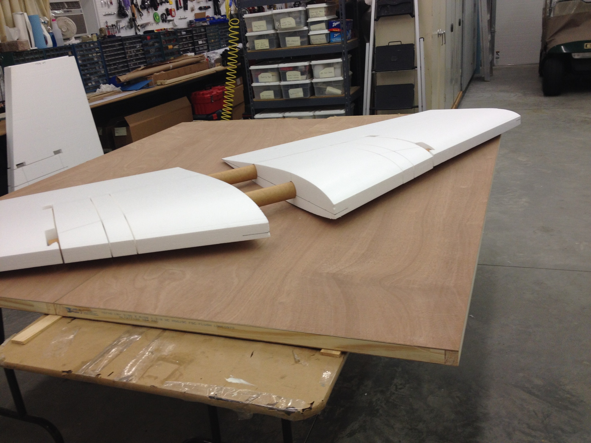
Wing panels joined together with wing tube sockets, it really came out pretty good
JAN 2014
The foam cutter work perfectly and I developed confidence it the process.
The ropes were re-routed as described in Curtis Suter's article
Second cut on bottom of core started
Second cut almost complete
Bottom shuck removed
Left wing panel cut complete…it came out very well
A TLAR quality control look a the left panel
Right panel bottom cut ready to go
Right panel bottom cut complete
Another cut and it was done
Wing panels joined together with wing tube sockets, it really came out pretty good
01-18-2015, 11:45 AM
#40
Thread Starter
My Feedback: (20)
Sabre XLT Making wing ribs
JAN 2014
After foam cores were cut it was time to make the wing half ribs. The first two ribs hold the main landing gear mounts. The last rib supports the end of the wing tubes


Rib blanks inserted into pre-cut slots
Wing tube sleeves inserted through ribs
Shape of ribs traced over the foam core
Location of landing gear mounts determined by some more of Gary's CAD (Come Along Design) on the paper drawings of the enlarged Lancer wing


Landing gear placement checked by TLAR method
Landing gear placement marked on rib blanks
Rib blanks removed for more CAD
Gary's CAD tools in use...
JAN 2014
After foam cores were cut it was time to make the wing half ribs. The first two ribs hold the main landing gear mounts. The last rib supports the end of the wing tubes
Rib blanks inserted into pre-cut slots
Wing tube sleeves inserted through ribs
Shape of ribs traced over the foam core
Location of landing gear mounts determined by some more of Gary's CAD (Come Along Design) on the paper drawings of the enlarged Lancer wing
Landing gear placement checked by TLAR method
Landing gear placement marked on rib blanks
Rib blanks removed for more CAD
Gary's CAD tools in use...
Last edited by Viper1GJ; 01-18-2015 at 11:47 AM.
01-18-2015, 11:58 AM
#41
Thread Starter
My Feedback: (20)
Sabre XLT Making wing ribs
JAN 2014


CAD complete on first rib, wing thickness and sweep had to be plotted on paper to locate the gear mount
Cut outs made on first rib
Gear mount pattern transfered to next rib by aligning the wing tube holes


Gear mount being cut out from R1
Gear mount cut outs complete
Lightening holes cut in ribs
Both rib sets complete
JAN 2014
CAD complete on first rib, wing thickness and sweep had to be plotted on paper to locate the gear mount
Cut outs made on first rib
Gear mount pattern transfered to next rib by aligning the wing tube holes
Gear mount being cut out from R1
Gear mount cut outs complete
Lightening holes cut in ribs
Both rib sets complete
01-18-2015, 12:24 PM
#42
Thread Starter
My Feedback: (20)
Sabre XLT Making main gear mounts and wheel wells
FEB 2014
Landing gear mounts were figured out on the parts and then parts made.


Landing gear plates planned and drawn on foam
Wheel wells planned and drawn on foam
TLAR inspection of the Come Along Design process
Drawings on both wing cores
Landing gear plates made from laminating two 1/4" pieces of plywood and cutting on table saw. Rib slots made by 1/8" depth of cut on table saw. Saw kerf was 1/8" wide.
Dry fitting landing gear plates. End slots were made by 1/4" depth of cut on table saw, steel ruler with cork backing is holding ribs up on foam


Dry fit of landing gear mounting plates
Landing gear mounting bolt holes drilled and bolts installed
Drawing for air cylinder made on foam and foam removal started with a hot wire cutter. I got the hot wire cutter from a craft store several years ago
Final cuts for gear mounting plates finished and gear well foam has been removed
FEB 2014
Landing gear mounts were figured out on the parts and then parts made.
Landing gear plates planned and drawn on foam
Wheel wells planned and drawn on foam
TLAR inspection of the Come Along Design process
Drawings on both wing cores
Landing gear plates made from laminating two 1/4" pieces of plywood and cutting on table saw. Rib slots made by 1/8" depth of cut on table saw. Saw kerf was 1/8" wide.
Dry fitting landing gear plates. End slots were made by 1/4" depth of cut on table saw, steel ruler with cork backing is holding ribs up on foam
Dry fit of landing gear mounting plates
Landing gear mounting bolt holes drilled and bolts installed
Drawing for air cylinder made on foam and foam removal started with a hot wire cutter. I got the hot wire cutter from a craft store several years ago
Final cuts for gear mounting plates finished and gear well foam has been removed
01-18-2015, 01:13 PM
#43
Thread Starter
My Feedback: (20)
Sabre XLT Making main gear mounts and wheel wells
FEB 2014


Landing gear dry fit into mounting holes
Both gear mounts and wells cut
Leveling the bottom of the wheel well. Shop vacuum hose really helps keep the foam dust under control
Palm sander smooths bottom of wheel well
Round channel cutter fitted into hot wire cutter
Preparing to cut retract air line channel freehand with hot wire cutter


Round hot wire channel cutter in exit hole
Fitting air lines on to landing gear and in air tube channel
Wing root exit hole for air lines
Final shape of gear mount foam removal
Another TLAR quality control check of both gear mounts...
FEB 2014
Landing gear dry fit into mounting holes
Both gear mounts and wells cut
Leveling the bottom of the wheel well. Shop vacuum hose really helps keep the foam dust under control
Palm sander smooths bottom of wheel well
Round channel cutter fitted into hot wire cutter
Preparing to cut retract air line channel freehand with hot wire cutter
Round hot wire channel cutter in exit hole
Fitting air lines on to landing gear and in air tube channel
Wing root exit hole for air lines
Final shape of gear mount foam removal
Another TLAR quality control check of both gear mounts...
01-18-2015, 02:42 PM
#44
Thread Starter
My Feedback: (20)
Sabre XLT Elevon servo mounts and wire channels
FEB 2014
The Sabre XLT will use two servos per elevon. Four servo mounts are installed two in each panel.


Servo mounts are laid out on foam using a cardboard pattern and more CAD/TLAR engineering
Servo mount locations traced on foam
Hot wire cutter used to cut out servo wells
Shallow channel cutter used to remove foam for plywood mounts
Foam cutter operated free hand


Foam removed from servo mount
Servo dry fitted in foam servo well
Servo wire channel cut using wood ruler as a straight edge guide. Depth of cut controlled by plywood depth gauge clamped to cutting wires
Servo channel core being removed
Servo channel core removed
Four 1/8" plywood servo mounting plates stacked together for cutting on scroll saw
FEB 2014
The Sabre XLT will use two servos per elevon. Four servo mounts are installed two in each panel.
Servo mounts are laid out on foam using a cardboard pattern and more CAD/TLAR engineering
Servo mount locations traced on foam
Hot wire cutter used to cut out servo wells
Shallow channel cutter used to remove foam for plywood mounts
Foam cutter operated free hand
Foam removed from servo mount
Servo dry fitted in foam servo well
Servo wire channel cut using wood ruler as a straight edge guide. Depth of cut controlled by plywood depth gauge clamped to cutting wires
Servo channel core being removed
Servo channel core removed
Four 1/8" plywood servo mounting plates stacked together for cutting on scroll saw
01-18-2015, 02:53 PM
#45
Thread Starter
My Feedback: (20)
Sabre XLT Elevon servo mounts and wire channels
FEB 2014


Plywood servo mounts with doublers for mounting screws
Servo mount epoxied into foam with fiberglass laminated on top
Excess epoxy absorbed into paper towel with rubber squeegee
Plastic sheet taped over servo mount
Wing shucks weighted over servo mounts till epoxy cures
Fiberglass cut out of servo well hole


Servo well edges sanded smooth
Dry fit of servo and wire in wire channel
All four servo mounts complete
FEB 2014
Plywood servo mounts with doublers for mounting screws
Servo mount epoxied into foam with fiberglass laminated on top
Excess epoxy absorbed into paper towel with rubber squeegee
Plastic sheet taped over servo mount
Wing shucks weighted over servo mounts till epoxy cures
Fiberglass cut out of servo well hole
Servo well edges sanded smooth
Dry fit of servo and wire in wire channel
All four servo mounts complete
01-18-2015, 03:01 PM
#46
Thread Starter
My Feedback: (20)
Sabre XLT Installing wing ribs and wing tube sockets
FEB 2014
Ribs and wing tube sockets are installed using polyurethane glue. I found it an excellent glue for use with the foam because of the expanding properties that gripped very tight and filled any voids and my mistakes.


Wing tube sockets marked for cutting
Socket tubes cut on scroll saw
Plastic laid on shucks to keep glue squeeze out from permanently gluing the cores to the shucks
Socket tubes all cut and marked
End of socket tubes taped closed to keep glue from getting inside the socket tube when inserting into foam


Prep layout for putting glue on ribs and socket tubes
The next steps were too messy to take photos. You have to work quickly because glue foaming starts in a few minutes.
All the parts were rubbed with a damp wash cloth.
Each rib was coated on both sides with glue using a small brush. They were then inserted into the correct slots and squeeze out wiped off
Then each tube socket was coated with glue and inserted into the tube holes locking in the ribs. The squeeze out was wiped off
Plastic applied to top of cores to protect glue from getting on top shuck
Top shucks applied onto cores and weighted. Glue cures pretty quickly and foams out of openings. Once cured the glue foam it is easily sanded or cut off.
FEB 2014
Ribs and wing tube sockets are installed using polyurethane glue. I found it an excellent glue for use with the foam because of the expanding properties that gripped very tight and filled any voids and my mistakes.
Wing tube sockets marked for cutting
Socket tubes cut on scroll saw
Plastic laid on shucks to keep glue squeeze out from permanently gluing the cores to the shucks
Socket tubes all cut and marked
End of socket tubes taped closed to keep glue from getting inside the socket tube when inserting into foam
Prep layout for putting glue on ribs and socket tubes
The next steps were too messy to take photos. You have to work quickly because glue foaming starts in a few minutes.
All the parts were rubbed with a damp wash cloth.
Each rib was coated on both sides with glue using a small brush. They were then inserted into the correct slots and squeeze out wiped off
Then each tube socket was coated with glue and inserted into the tube holes locking in the ribs. The squeeze out was wiped off
Plastic applied to top of cores to protect glue from getting on top shuck
Top shucks applied onto cores and weighted. Glue cures pretty quickly and foams out of openings. Once cured the glue foam it is easily sanded or cut off.
Last edited by Viper1GJ; 01-18-2015 at 03:31 PM.
01-19-2015, 06:44 AM
#47
Thread Starter
My Feedback: (20)
Sabre XLT Installing main gear mounts
FEB 2014
Main gear mounts were installed using West Systems epoxy mixed with colloidal silica.


Gear mount area after ribs glued in
Gear mount dry fit
Plastic sheet inserted between aluminum gear and plywood mounting plates to keep epoxy off aluminum parts


Vaseline applied to landing gear mounting bolts and blind nuts
Vaseline heated with low heat air gun to flow it into threads and nuts
Bolt and blind nut after heating vaseline
Epoxy mixing prep area using West System 206 slow hardener and 406 silica for thickening


Un-thickened epoxy applied to ribs and slots to allow it to "soak in" the foam and wood before thickened epoxy applied to fill gaps
Thickened epoxy then applied to ribs and slots
Glued up gear mount in place
Thickened epoxy squeeze out stays under plastic sheet for curing
FEB 2014
Main gear mounts were installed using West Systems epoxy mixed with colloidal silica.
Gear mount area after ribs glued in
Gear mount dry fit
Plastic sheet inserted between aluminum gear and plywood mounting plates to keep epoxy off aluminum parts
Vaseline applied to landing gear mounting bolts and blind nuts
Vaseline heated with low heat air gun to flow it into threads and nuts
Bolt and blind nut after heating vaseline
Epoxy mixing prep area using West System 206 slow hardener and 406 silica for thickening
Un-thickened epoxy applied to ribs and slots to allow it to "soak in" the foam and wood before thickened epoxy applied to fill gaps
Thickened epoxy then applied to ribs and slots
Glued up gear mount in place
Thickened epoxy squeeze out stays under plastic sheet for curing
01-19-2015, 11:32 PM
#48
One of the biggest regrets on my jet was how I mounted the aileron & flap servos, hanging out in the breeze.
A wheels up landing on a friends model which ripped the top of a couple of similarly mounted servos led to me
make protective covers for mine but it would have looked so much better if I mounted them flush on their sides
as I usually do. By the time I made & fitted the covers it was a lot more work than my usual method.
Probably your last chance if you change your mind before sheeting. - John.
01-20-2015, 03:50 AM
#49
Join Date: Jan 2007
Location: farnborough, , UNITED KINGDOM
Posts: 3,294
Likes: 0
Received 1 Like
on
1 Post
Servos on their sides also allows for an inline pull/push action.
Great thread to watch and super skills with foam - never spent much time working with foam so this is a great tutorial.
marcs
Great thread to watch and super skills with foam - never spent much time working with foam so this is a great tutorial.
marcs
01-20-2015, 06:37 AM
#50
Thread Starter
My Feedback: (20)
Hi John, Marcs
Very good point. I had not really thought of the gear up landing hazard to servos. I have got so used to mounting them this way in most IMAC and sport planes, (which have no retracts) it never occurred to me. I can see the problem right away.
However, the wing was sheeted in APR 2014 (see post #9). I have got gotten those photos posted yet.
I would have to modify the existing mounts to do it. Or I could make some fiberglass covers like you mentioned similar to the "canoe" flap hinge covers on an airliner. I agree with the inline push-pull action. In this case how would you protect the servo arm from the gear up landing?
I was only thinking easy, fast and cheap when I started the project. I will think about it. If you have any suggestions please post.
Thanks,
Gary