


Sabre XLT – A large scratch built flying wing sport jet
 01-20-2015, 07:30 AM
#51

Thread Starter
My Feedback: (20)
Sabre XLT Installing main gear mount top plates
FEB 2014
The following steps were completed during the ice storm that crushed South Carolina in FEB 2014. The power was off for several days. But there was time off, so work proceeded on generator power.
Some more of Gary's CAD/TLAR applied here. After looking at the forces that would be on the gear mounts during a hard landing, especially with the swept back gear struts, I wanted to tie the bottom front gear plate to the top surface of the wing ribs. The idea was the bottom mount would be trying to be pulled out and to the rear, so I wanted it to have to pull thru the foam to do it. So I added the top plates and carbon fiber tubes to tie the top and bottom together and laminated the area with carbon cloth.


Only lights in the shop were two generator powered flood lights
Top plate position marked on foam
Hot wire cutter removed foam for 1/8" top plate
Perma-Grit grinder removed the plywood rib wood


Top plate ready for glue
Top plate dry fit
In this photo you can see the poly glue foam out on the wing ribs. This was later removed with the Perma-Grit grinder seen above to be flush with the foam surface
Thickened epoxy use for the top plate adhesive and scraped smooth to top surface to fill the gaps


Un-thickened epoxy used to laminate the carbon cloth and spread with squeegee
Excess epoxy soaked up with paper towel
Both wings complete. Plastic sheets applied over the wetted areas
Top wing shucks on and weighted to cure epoxy


After epoxy cured holes were drilled through the bottom front gear plate all the way through the top plate and carbon cloth
Carbon tube inserted into hole
One tube in one to go
After the tubes dry fit was good, the tubes were epoxied into holes and to bottom gear plate and top gear plate
After curing the tubes were cut and sanded flush with top surface
FEB 2014
The following steps were completed during the ice storm that crushed South Carolina in FEB 2014. The power was off for several days. But there was time off, so work proceeded on generator power.
Some more of Gary's CAD/TLAR applied here. After looking at the forces that would be on the gear mounts during a hard landing, especially with the swept back gear struts, I wanted to tie the bottom front gear plate to the top surface of the wing ribs. The idea was the bottom mount would be trying to be pulled out and to the rear, so I wanted it to have to pull thru the foam to do it. So I added the top plates and carbon fiber tubes to tie the top and bottom together and laminated the area with carbon cloth.
Only lights in the shop were two generator powered flood lights
Top plate position marked on foam
Hot wire cutter removed foam for 1/8" top plate
Perma-Grit grinder removed the plywood rib wood
Top plate ready for glue
Top plate dry fit
In this photo you can see the poly glue foam out on the wing ribs. This was later removed with the Perma-Grit grinder seen above to be flush with the foam surface
Thickened epoxy use for the top plate adhesive and scraped smooth to top surface to fill the gaps
Un-thickened epoxy used to laminate the carbon cloth and spread with squeegee
Excess epoxy soaked up with paper towel
Both wings complete. Plastic sheets applied over the wetted areas
Top wing shucks on and weighted to cure epoxy
After epoxy cured holes were drilled through the bottom front gear plate all the way through the top plate and carbon cloth
Carbon tube inserted into hole
One tube in one to go
After the tubes dry fit was good, the tubes were epoxied into holes and to bottom gear plate and top gear plate
After curing the tubes were cut and sanded flush with top surface
 01-20-2015, 10:08 AM
#52
Thread Starter
My Feedback: (20)
Sabre XLT Sheeting gear wells
FEB 2014
Lights back on in shop this week and work continues.


Scribing gear well bottom pattern on sheet balsa
Pattern cut out by hobby knife on cutting mat
Well bottom glued in with wood glue
Wheel well side sheeting ready for dry fit
Side sheeting dry fit


Side sheeting glued in and pressed against foam by weighted socks.
Cleaning up glue squeeze out on mounting plates
Flush grinding ribs and poly glue squeeze out on leading edge
Flush grinding carbon tubes on front gear mount plate
Flush cutting balsa filler around gear mount
Flush cutting gear well side sheeting


Gear well sanded flush ready for carbon laminate
Pattern for carbon laminate
Carbon fabric sprayed with hair spray before cutting out pattern keeps weaving from falling apart
Cutting carbon fabric with rotary cutter on cutting mat
Carbon fabric pattern traced on foam
Carbon fabric wetted out with epoxy


Excess epoxy soaked up with paper towel, I did this two or three times to remove all excess epoxy
Wetted out area covered with plastic sheet to prevent shucks from sticking
Bottom shucks weighted over laminated area for curing
FEB 2014
Lights back on in shop this week and work continues.
Scribing gear well bottom pattern on sheet balsa
Pattern cut out by hobby knife on cutting mat
Well bottom glued in with wood glue
Wheel well side sheeting ready for dry fit
Side sheeting dry fit
Side sheeting glued in and pressed against foam by weighted socks.
Cleaning up glue squeeze out on mounting plates
Flush grinding ribs and poly glue squeeze out on leading edge
Flush grinding carbon tubes on front gear mount plate
Flush cutting balsa filler around gear mount
Flush cutting gear well side sheeting
Gear well sanded flush ready for carbon laminate
Pattern for carbon laminate
Carbon fabric sprayed with hair spray before cutting out pattern keeps weaving from falling apart
Cutting carbon fabric with rotary cutter on cutting mat
Carbon fabric pattern traced on foam
Carbon fabric wetted out with epoxy
Excess epoxy soaked up with paper towel, I did this two or three times to remove all excess epoxy
Wetted out area covered with plastic sheet to prevent shucks from sticking
Bottom shucks weighted over laminated area for curing
01-20-2015, 10:46 AM
#53
Thread Starter
My Feedback: (20)
Sabre XLT Installing carbon fiber spars
MAR 2014
Mike Oser suggested the Sabre XLT would be able to turn very tight corners and could pull 20 Gs. I put that into my CAD/TLAR computer and decided to add carbon spars on top and bottom. Not sure if it would make a real difference but all jets have to have carbon fiber to be cool. Sooo...


Carbon tube spar location marked on wing core
Dremel tool router attachment tested for depth of cut. Vacuum keeps foam dust under control
6' ruller taped to wing core to provide guide for spar channel cut
Router cuts came out very well
Carbon spar dry fit was very tight and flush with surface


Carbon spar epoxied in and bridges the tow outboard ribs over the wing tube
A few TLAR quality control photos
MAR 2014
Mike Oser suggested the Sabre XLT would be able to turn very tight corners and could pull 20 Gs. I put that into my CAD/TLAR computer and decided to add carbon spars on top and bottom. Not sure if it would make a real difference but all jets have to have carbon fiber to be cool. Sooo...
Carbon tube spar location marked on wing core
Dremel tool router attachment tested for depth of cut. Vacuum keeps foam dust under control
6' ruller taped to wing core to provide guide for spar channel cut
Router cuts came out very well
Carbon spar dry fit was very tight and flush with surface
Carbon spar epoxied in and bridges the tow outboard ribs over the wing tube
A few TLAR quality control photos
01-20-2015, 07:14 PM
#56
Thread Starter
My Feedback: (20)
Sabre XLT Making wing skins
MAR 2014
Wing skins were fabricated from 3/32" x 3" x 48" balsa sheets.


Balsa sheet edge sander. It is a Melamine base with 90 degree aluminum angle edge attached and 80 grit sanding strip glued to aluminum angle.
Sanding bar is a Melamine cap with foam block attached to bottom with 3 pieces of 80 grit sand paper glued to foam base. Homemade down draft sanding table helps control dust.
Sheets being laid out on foam core after edge sanding
Sheets being edge glued with thin CA over wax paper


Small fan keeps air moving across work area to blow CA fumes away
First wing skin done and trimmed
All four skins completed and trimmed awaiting sanding


Sanding setup uses ceiling mounted dust collector, down draft sanding table, and shop vacuum attached to sander to control dust
Orbital oscillating sander with180 grit sanding pad attached to shop vacuum makes fast work of sanding wing skins and keeps dust under control
All skins finished with sanding
I did not mention it but I hate sanding….
MAR 2014
Wing skins were fabricated from 3/32" x 3" x 48" balsa sheets.
Balsa sheet edge sander. It is a Melamine base with 90 degree aluminum angle edge attached and 80 grit sanding strip glued to aluminum angle.
Sanding bar is a Melamine cap with foam block attached to bottom with 3 pieces of 80 grit sand paper glued to foam base. Homemade down draft sanding table helps control dust.
Sheets being laid out on foam core after edge sanding
Sheets being edge glued with thin CA over wax paper
Small fan keeps air moving across work area to blow CA fumes away
First wing skin done and trimmed
All four skins completed and trimmed awaiting sanding
Sanding setup uses ceiling mounted dust collector, down draft sanding table, and shop vacuum attached to sander to control dust
Orbital oscillating sander with180 grit sanding pad attached to shop vacuum makes fast work of sanding wing skins and keeps dust under control
All skins finished with sanding
I did not mention it but I hate sanding….
01-20-2015, 07:29 PM
#57
Thread Starter
My Feedback: (20)
Sabre XLT Making wing skin map
MAR 2014
It occurred to me that if I glued the wing skins on and covered up all the gear and servo holes I would have no clue where to cut them out. So I made a wing skin map. A used the back of an old aviation map to make a "map" of the wing skin holes.


The paper was taped to the foam core and registration marks made on the ends of the cores to allow placement after balsa skins were attached
Servo cut out locations
Gear well location
Gear well opening being cut out


Registration lines on wing root foam
Registration lines on wing tip foam
Paper wing skin map removed and stored for later use
MAR 2014
It occurred to me that if I glued the wing skins on and covered up all the gear and servo holes I would have no clue where to cut them out. So I made a wing skin map. A used the back of an old aviation map to make a "map" of the wing skin holes.
The paper was taped to the foam core and registration marks made on the ends of the cores to allow placement after balsa skins were attached
Servo cut out locations
Gear well location
Gear well opening being cut out
Registration lines on wing root foam
Registration lines on wing tip foam
Paper wing skin map removed and stored for later use
Last edited by Viper1GJ; 01-20-2015 at 07:32 PM.
01-22-2015, 05:43 PM
#58
Thread Starter
My Feedback: (20)
Sabre XLT Setting up vacuum bags
APR 2014


Aerospace Composites vacuum pump dusted off and tested. Scientific test method is to put the vacuum tube in your mouth and if your cheeks slam together it is working!
Wing shucks taped together where hot wire cuts made for wing tubes and ribs
1/4 felt batting material from JoAnn fabric store used for breather cloth. Batting felt cut to wing skin shape
Vacuum bag material is 4mil plastic from from Lowes' left over from a concrete project vapor barrier. It comes on a roll that unfolds to 12' wide. The trailing edge is folded over so no caulking is needed on trailing edge for the vacuum seal


Fold line is marked to make it easier to see and fold
Wing skins trailing edge taped together so they can be book folded over the foam cores
Work area is prepared for glue application and moving to vacuum bag
Wing skins unfolded and ready
Line drawn 3/8" inside the skins trailing edge to align the foam cores after glue application. The balsa overlap extends about 3/8" aft of the trailing edge


Foam trailing edge line marked
I ask my wife to help with moving the cores to the vacuum bag and building the vacuum bag stack. A dry run of folding and moving to vacuum bag was made before glue applied.
Skins book folded over foam core and ready for movement to vacuum bag
Top shuck is stacked over vacuum bag and location of vacuum line nipples marked
The stack for the vacuum bag goes like this:
Top foam shuck
Top plastic sheet of vacuum bag
Top wing shaped breather cloth
Top wing shaped plastic sheet separator to keep glue squeeze out from gluing breather cloth to balsa skins
Top balsa wing skin
Foam core
Bottom balsa wing skin
Bottom wing shaped plastic sheet separator to keep glue squeeze out from gluing breather cloth to balsa skins
Bottom wing shaped breather cloth
Bottom plastic sheet of vacuum bag
Bottom foam shuck


Vacuum bag plastic removed from stack to install vacuum line air nipples into plastic sheet
Air line test fitted to nipple
Vacuum pump attached to nipples and ready
Wing skins unfolded and ready to glue
Vacuum bag staged and ready to accept wing cores. Scrap foam blocks help elevate plastic to center line of root and tip ribs to avoid wrinkles. Plastic containers on floor hold top of fan folded vacuum bag to make it easier to fold over the cores when ready. The dry run and preparation was the key to success here.
APR 2014
Aerospace Composites vacuum pump dusted off and tested. Scientific test method is to put the vacuum tube in your mouth and if your cheeks slam together it is working!
Wing shucks taped together where hot wire cuts made for wing tubes and ribs
1/4 felt batting material from JoAnn fabric store used for breather cloth. Batting felt cut to wing skin shape
Vacuum bag material is 4mil plastic from from Lowes' left over from a concrete project vapor barrier. It comes on a roll that unfolds to 12' wide. The trailing edge is folded over so no caulking is needed on trailing edge for the vacuum seal
Fold line is marked to make it easier to see and fold
Wing skins trailing edge taped together so they can be book folded over the foam cores
Work area is prepared for glue application and moving to vacuum bag
Wing skins unfolded and ready
Line drawn 3/8" inside the skins trailing edge to align the foam cores after glue application. The balsa overlap extends about 3/8" aft of the trailing edge
Foam trailing edge line marked
I ask my wife to help with moving the cores to the vacuum bag and building the vacuum bag stack. A dry run of folding and moving to vacuum bag was made before glue applied.
Skins book folded over foam core and ready for movement to vacuum bag
Top shuck is stacked over vacuum bag and location of vacuum line nipples marked
The stack for the vacuum bag goes like this:
Top foam shuck
Top plastic sheet of vacuum bag
Top wing shaped breather cloth
Top wing shaped plastic sheet separator to keep glue squeeze out from gluing breather cloth to balsa skins
Top balsa wing skin
Foam core
Bottom balsa wing skin
Bottom wing shaped plastic sheet separator to keep glue squeeze out from gluing breather cloth to balsa skins
Bottom wing shaped breather cloth
Bottom plastic sheet of vacuum bag
Bottom foam shuck
Vacuum bag plastic removed from stack to install vacuum line air nipples into plastic sheet
Air line test fitted to nipple
Vacuum pump attached to nipples and ready
Wing skins unfolded and ready to glue
Vacuum bag staged and ready to accept wing cores. Scrap foam blocks help elevate plastic to center line of root and tip ribs to avoid wrinkles. Plastic containers on floor hold top of fan folded vacuum bag to make it easier to fold over the cores when ready. The dry run and preparation was the key to success here.
Last edited by Viper1GJ; 01-22-2015 at 06:45 PM.
01-22-2015, 05:45 PM
#59
Thread Starter
My Feedback: (20)
Sabre XLT Applying glue to the skins
APR 2014
My wife took these photos while glue was spread. She later helped move the cores to the vacuum bag, position the breather cloth, and fold over the top bag plastic. Two people really helped make this process work more quickly.


One coat of Zinsser's Seal Coat was applied to inside of the wing skins with a roller and brush to seal the wood. I read this stops glue from soaking in the balsa and adding weight. Don't know if it helped but it did not hurt. It dries very fast and skins were ready to glue in about 20 min.
First the balsa skins were lightly wiped with a water moistened towel. Then Gorilla polyurethane glue was spread with a plastic auto body squeegee.


I worked quickly to get glue spread before the water in the wood started kicking it off and foaming starts. Gloves are a must for this part.
Excess glue was scraped out of the trailing edge tape gap with cotton Q-tip
APR 2014
My wife took these photos while glue was spread. She later helped move the cores to the vacuum bag, position the breather cloth, and fold over the top bag plastic. Two people really helped make this process work more quickly.
One coat of Zinsser's Seal Coat was applied to inside of the wing skins with a roller and brush to seal the wood. I read this stops glue from soaking in the balsa and adding weight. Don't know if it helped but it did not hurt. It dries very fast and skins were ready to glue in about 20 min.
First the balsa skins were lightly wiped with a water moistened towel. Then Gorilla polyurethane glue was spread with a plastic auto body squeegee.
I worked quickly to get glue spread before the water in the wood started kicking it off and foaming starts. Gloves are a must for this part.
Excess glue was scraped out of the trailing edge tape gap with cotton Q-tip
Last edited by Viper1GJ; 01-22-2015 at 06:40 PM.
01-23-2015, 06:19 AM
#60
Thread Starter
My Feedback: (20)
Sabre XLT Vacuum bagging wing skins
APR 2014


After glue is applied to skins the foam core is placed on bottom skin and top skin is book folded over the core. The core and skins are transferred to the vacuum bag and plastic separator, breather cloth, and top of bag are folded on top. The parts are aligned and then caulking is applied to seal the edges of the bag. This process was done quickly with help from my wife so no photos were taken
Vacuum pump is connected to air nipples and pump turned on
The plastic is smoothed out as the air is sucked out
Paint can weights were applied to hold the top shuck down


The vacuum flattens out the caulk bead as air is removed from the bag
Sock weights applied to top shuck to hold leading edge down
Vacuum pressure is 8psi. I learned later that 6-7 psi would have been plenty as the vacuum pulled the balsa skins into the wheel wells
Vacuum pressure sucks the plastic bag around the balsa skin overhang and into wing tube holes


A strip of breather cloth material was laid over the wing breather cloth and out to the air nipple to allow an air channel to the main part of the vacuum bag. Glue was allowed to cure overnight
This is the second core with weights removed ready to be removed from bag showing the bag, caulking, breather cloth strips, and pump
On the second wing I caulked all the way around. It was easier than managing the fold on the trailing edge
The second core was easier because of the lessons learned doing the first one
Vacuum lines removed and air flowing back into the bag
Second wing ready to get cut out of bag
APR 2014
After glue is applied to skins the foam core is placed on bottom skin and top skin is book folded over the core. The core and skins are transferred to the vacuum bag and plastic separator, breather cloth, and top of bag are folded on top. The parts are aligned and then caulking is applied to seal the edges of the bag. This process was done quickly with help from my wife so no photos were taken
Vacuum pump is connected to air nipples and pump turned on
The plastic is smoothed out as the air is sucked out
Paint can weights were applied to hold the top shuck down
The vacuum flattens out the caulk bead as air is removed from the bag
Sock weights applied to top shuck to hold leading edge down
Vacuum pressure is 8psi. I learned later that 6-7 psi would have been plenty as the vacuum pulled the balsa skins into the wheel wells
Vacuum pressure sucks the plastic bag around the balsa skin overhang and into wing tube holes
A strip of breather cloth material was laid over the wing breather cloth and out to the air nipple to allow an air channel to the main part of the vacuum bag. Glue was allowed to cure overnight
This is the second core with weights removed ready to be removed from bag showing the bag, caulking, breather cloth strips, and pump
On the second wing I caulked all the way around. It was easier than managing the fold on the trailing edge
The second core was easier because of the lessons learned doing the first one
Vacuum lines removed and air flowing back into the bag
Second wing ready to get cut out of bag
01-23-2015, 06:36 AM
#61
Thread Starter
My Feedback: (20)
Sabre XLT Vacuum bagging complete
APR 2014


The results were fantastic. For my first time vacuum bagging I was really happy. Poly glue is incredible. It is now my glue of choice for wing skins.
APR 2014
The results were fantastic. For my first time vacuum bagging I was really happy. Poly glue is incredible. It is now my glue of choice for wing skins.
01-23-2015, 08:56 AM
#62
Join Date: Jul 2006
Location: Norfolk , UNITED KINGDOM
Posts: 1,409
Likes: 0
Received 0 Likes
on
0 Posts
Gary
Very nice tutorial, and it is a while since we saw someone doing things the hard way! I expected that the build would go pretty smoothly when I saw the very neat workshop. I love flying wings and just about ready to start my next project. As you rightly say this is one big plane and I am sure will turn out light in weight. Mine will be slightly smaller but has no fin and no fuselage.
John
 01-24-2015, 08:44 AM
#64
Thread Starter
My Feedback: (20)
Sabre XLT Trimming wing skins
APR 2014
I forgot to post these wing skin trimming photos before the ones in post #61


Root end of wing showing well glued wing skins
8 psi vacuum pressure was enough to crush the skins over the wheel well. Probably 6-7 psi would have been better
Flush cutting root skin overhang
Flush sanding root skins


Flush sanding root skins
Flush cutting tip overhang
Flush sanding leading edge
Final leading edge rear for leading edge cap
Now you can see the final results of the vacuum bagging process in post #61
APR 2014
I forgot to post these wing skin trimming photos before the ones in post #61
Root end of wing showing well glued wing skins
8 psi vacuum pressure was enough to crush the skins over the wheel well. Probably 6-7 psi would have been better
Flush cutting root skin overhang
Flush sanding root skins
Flush sanding root skins
Flush cutting tip overhang
Flush sanding leading edge
Final leading edge rear for leading edge cap
Now you can see the final results of the vacuum bagging process in post #61
01-24-2015, 09:54 AM
#65
Thread Starter
My Feedback: (20)
Sabre XLT Mapping and cutting wing skin holes
APR 2014
Cutting wheel wells and servo pockets in wing skins


Paper wing skin map taped in place with registration marks on foam core
Cutout for wheel wells traced
Cut out for servo pockets traced
Wheel well being cut out


Wheel well being trimmed out
Wheel well edges being sanded with curved Perma Grit tool
Finished wheel well
Servo pockets trimmed out with knife and chisel
All wing skin holes cut out and ready
APR 2014
Cutting wheel wells and servo pockets in wing skins
Paper wing skin map taped in place with registration marks on foam core
Cutout for wheel wells traced
Cut out for servo pockets traced
Wheel well being cut out
Wheel well being trimmed out
Wheel well edges being sanded with curved Perma Grit tool
Finished wheel well
Servo pockets trimmed out with knife and chisel
All wing skin holes cut out and ready
01-24-2015, 11:57 AM
#66
Thread Starter
My Feedback: (20)
Sabre XLT Fuse planning and drawing
NOV 2014
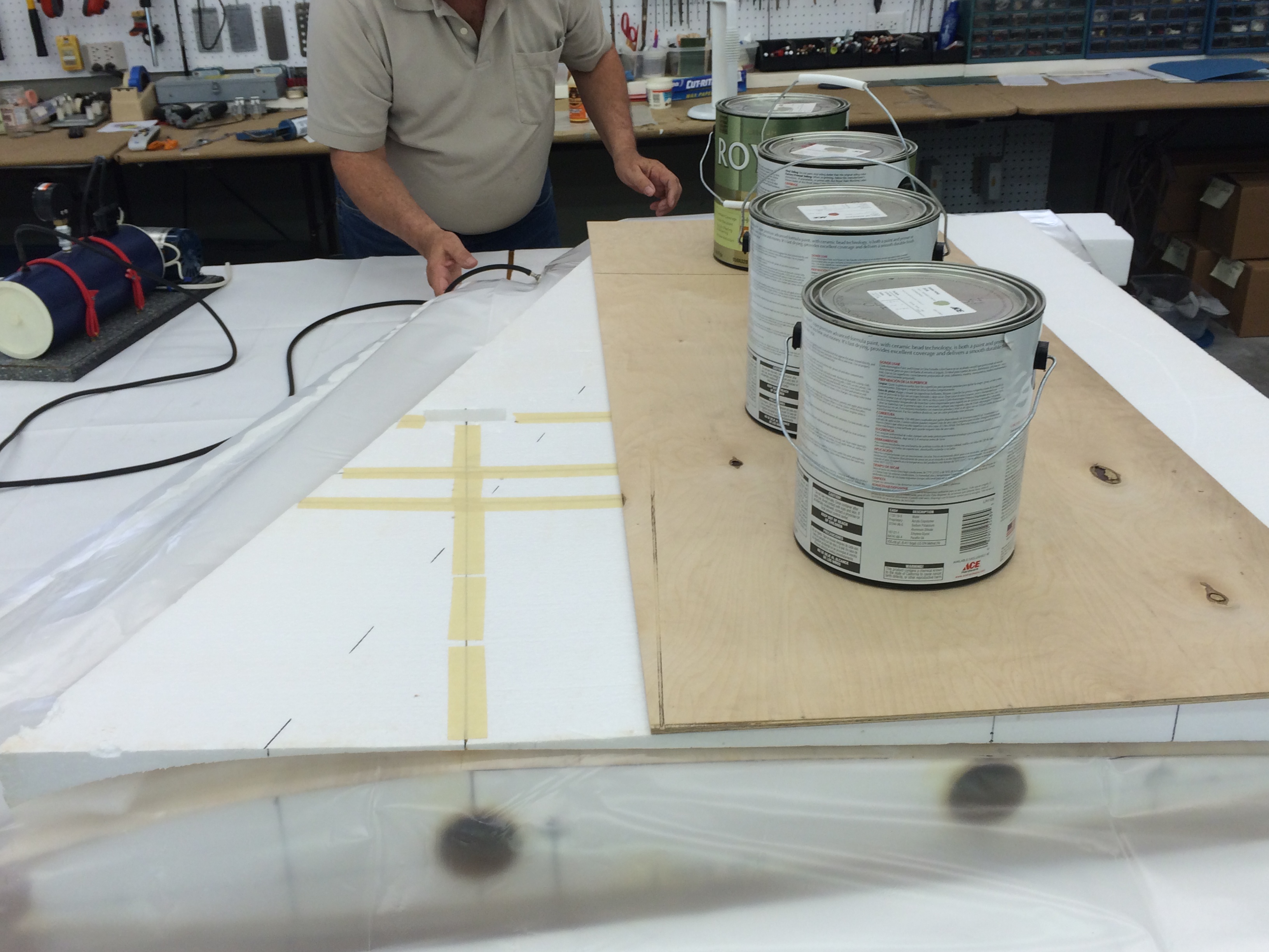
Shortly after the wings were vacuum bagged work on the Sabre XLT stopped due to a death in the family. This break continued into the summer with several trips both planned and unplanned and a decision to retire early at the end of the year. I managed to get to a couple of RC fly-ins including Super Jets South 2014 in Georgia. After this my non-RC schedule was non-stop till after Christmas and no construction work was accomplished. I did find a couple of days to do some fuse planning and drawing. I sketched out a full size concept drawing for the Sabre fuse and sent these plans to Mike Oser who started a fantastic CAD project for the fuse plans.


Door table tops stacked end to end to make drawing table long enough for the fuse drawing
Enlarged Lancer plans on table to use as a pattern
Wing tube locations transferred from wing plans to fuse plan
Main landing gear installed in wings to measure distance from wing to ground


Distance from wings to ground needed to plan nose gear location in the fuse
Canopy, tank, and nose gear planning on fuse drawing
Gary's CAD (Come Along Design) tools in use
Nose section concept drawing for Sabre. The Sabre nose is longer that the Lancer to offset the weight of the engine in the tail


Full size paper concept drawing of the Sabre fuse side and top view
Thurst vector nozzle and engine placement in tail
After Mike uploaded my drawing into CAD he sent me a series of several drawings which we discussed via email and sketches. The green is my Sabre sketch superimposed on the Lancer drawing.
Mike suggested several changes that were incorporated in several drawings to which I added pencil lines and comments then scanned and returned to him. This is a general former construction concept I sent back to him.


This is one of the Sabre fuse drawings I sent back to Mike and his return CAD drawing.
Mike was able to create some really cool 3D pictures of the internal design as we continued to work together on the fuse design. These are some early samples of how the fuse plans were developed
I am very grateful for Mike's willingness to help design the turbine powered version of his Lancer design. His aerodynamic knowledge and CAD expertise are invaluable
NOV 2014
Shortly after the wings were vacuum bagged work on the Sabre XLT stopped due to a death in the family. This break continued into the summer with several trips both planned and unplanned and a decision to retire early at the end of the year. I managed to get to a couple of RC fly-ins including Super Jets South 2014 in Georgia. After this my non-RC schedule was non-stop till after Christmas and no construction work was accomplished. I did find a couple of days to do some fuse planning and drawing. I sketched out a full size concept drawing for the Sabre fuse and sent these plans to Mike Oser who started a fantastic CAD project for the fuse plans.
Door table tops stacked end to end to make drawing table long enough for the fuse drawing
Enlarged Lancer plans on table to use as a pattern
Wing tube locations transferred from wing plans to fuse plan
Main landing gear installed in wings to measure distance from wing to ground
Distance from wings to ground needed to plan nose gear location in the fuse
Canopy, tank, and nose gear planning on fuse drawing
Gary's CAD (Come Along Design) tools in use
Nose section concept drawing for Sabre. The Sabre nose is longer that the Lancer to offset the weight of the engine in the tail
Full size paper concept drawing of the Sabre fuse side and top view
Thurst vector nozzle and engine placement in tail
After Mike uploaded my drawing into CAD he sent me a series of several drawings which we discussed via email and sketches. The green is my Sabre sketch superimposed on the Lancer drawing.
Mike suggested several changes that were incorporated in several drawings to which I added pencil lines and comments then scanned and returned to him. This is a general former construction concept I sent back to him.
This is one of the Sabre fuse drawings I sent back to Mike and his return CAD drawing.
Mike was able to create some really cool 3D pictures of the internal design as we continued to work together on the fuse design. These are some early samples of how the fuse plans were developed
I am very grateful for Mike's willingness to help design the turbine powered version of his Lancer design. His aerodynamic knowledge and CAD expertise are invaluable
01-24-2015, 12:20 PM
#67
Thread Starter
My Feedback: (20)
Sabre XLT CAD 3D drawings
Here are some of the 3D photos that Mike recently sent me. I will post them here for motivation. I think the Sabre XLT will looks cool and be really different from most sport jets.


Some really cool inflight 3D CAD photos of the latest fuse design


Mike titled this one "Size Matters"
The latest air inlet design
Here are some of the 3D photos that Mike recently sent me. I will post them here for motivation. I think the Sabre XLT will looks cool and be really different from most sport jets.
Some really cool inflight 3D CAD photos of the latest fuse design
Mike titled this one "Size Matters"
The latest air inlet design
02-14-2015, 06:29 PM
#68
Thread Starter
My Feedback: (20)
Sabre XLT Cutting Elevons
DEC 2014
Work resumed just after Christmas 2014 after an 8 month break. I had to figure out where I left off and get started again. Cutting off the elevons was the first task.


Trailing edge trimmed with straight edge
Elevon cut outs marked with straight edge
3/4" spacer cut out marked for balsa edges
Bottom shuck taped to core to give a flat base for cutting


Right wing ready for cutting
Out feed rollers in position on band saw to catch wing panel after cutting
Out feed rollers tested for position
Wing in place for cutting on band saw


Elevon removed from wing and ready for final cut
Both elevons cut off. Built in wing dihedral can be seen in foam shucks
DEC 2014
Work resumed just after Christmas 2014 after an 8 month break. I had to figure out where I left off and get started again. Cutting off the elevons was the first task.
Trailing edge trimmed with straight edge
Elevon cut outs marked with straight edge
3/4" spacer cut out marked for balsa edges
Bottom shuck taped to core to give a flat base for cutting
Right wing ready for cutting
Out feed rollers in position on band saw to catch wing panel after cutting
Out feed rollers tested for position
Wing in place for cutting on band saw
Elevon removed from wing and ready for final cut
Both elevons cut off. Built in wing dihedral can be seen in foam shucks
02-16-2015, 06:03 PM
#69
Thread Starter
My Feedback: (20)
Sabre XLT Edging and Trimming Wings
DEC 2014
After elevons were cut off balsa leading and trailing edges were glued on with wood glue and trimmed.


Edge gluing elevon leading edge
Edge gluing wing leading and trailing edges
Wings ready for trimming
Dremel flush cut saw used to rough trim the balsa edges
Palm sander used to finish rough cuts over down draft dust collecting sanding table


Wing trailing edge finished
Wing leading edge rough cut and sanded
Elevon edges rough cut
Elevon edges sanded
End trimming elevon leading edge


End trimming wing leading edge at root
Wings ready for leading edge cap
Wing leading edge caps glued on
Wing leading edge cap trimming
DEC 2014
After elevons were cut off balsa leading and trailing edges were glued on with wood glue and trimmed.
Edge gluing elevon leading edge
Edge gluing wing leading and trailing edges
Wings ready for trimming
Dremel flush cut saw used to rough trim the balsa edges
Palm sander used to finish rough cuts over down draft dust collecting sanding table
Wing trailing edge finished
Wing leading edge rough cut and sanded
Elevon edges rough cut
Elevon edges sanded
End trimming elevon leading edge
End trimming wing leading edge at root
Wings ready for leading edge cap
Wing leading edge caps glued on
Wing leading edge cap trimming
02-17-2015, 10:40 AM
#70
My Feedback: (24)
Open question:
Has anyone used a flush-trim/laminate router bit to clean edges and wheel well or similar openings back?
Would seem to be a natural application using a trimrouter. Line the wheel wells, skin the wing then drill a hole and route out the openings. I've seen people use pattern bits and a template to route openings in wings. Just wondering what the most efficient/cleanest way to do this is. Having seen some absolutely factory looking perfect wings skinned and prepped (e.g. the old Yellow kits or BVM), i was just wondering how they got there. Can't imagine it was pure worker skill, though it might have been.
02-17-2015, 06:26 PM
#72
Thread Starter
My Feedback: (20)
Chuck, I never thought about using a router. I don't have a small one, I think mine would be to heavy to control on foam and balsa. Good idea however.
Jetster81, thanks. Its been fun, only wish I could get more time in the shop to get it done.
Jetster81, thanks. Its been fun, only wish I could get more time in the shop to get it done.
02-17-2015, 06:47 PM
#73
Thread Starter
My Feedback: (20)
Sabre XLT Wing Tips and Rails
DEC 2014
The next steps were to create double size missile rails and wing tips from Mike Oser's Lancer plans. Since there were no full size plans for this I used some of Gary's freestyle CAD (come along design) TLAR ( that looks about right) to make them up.


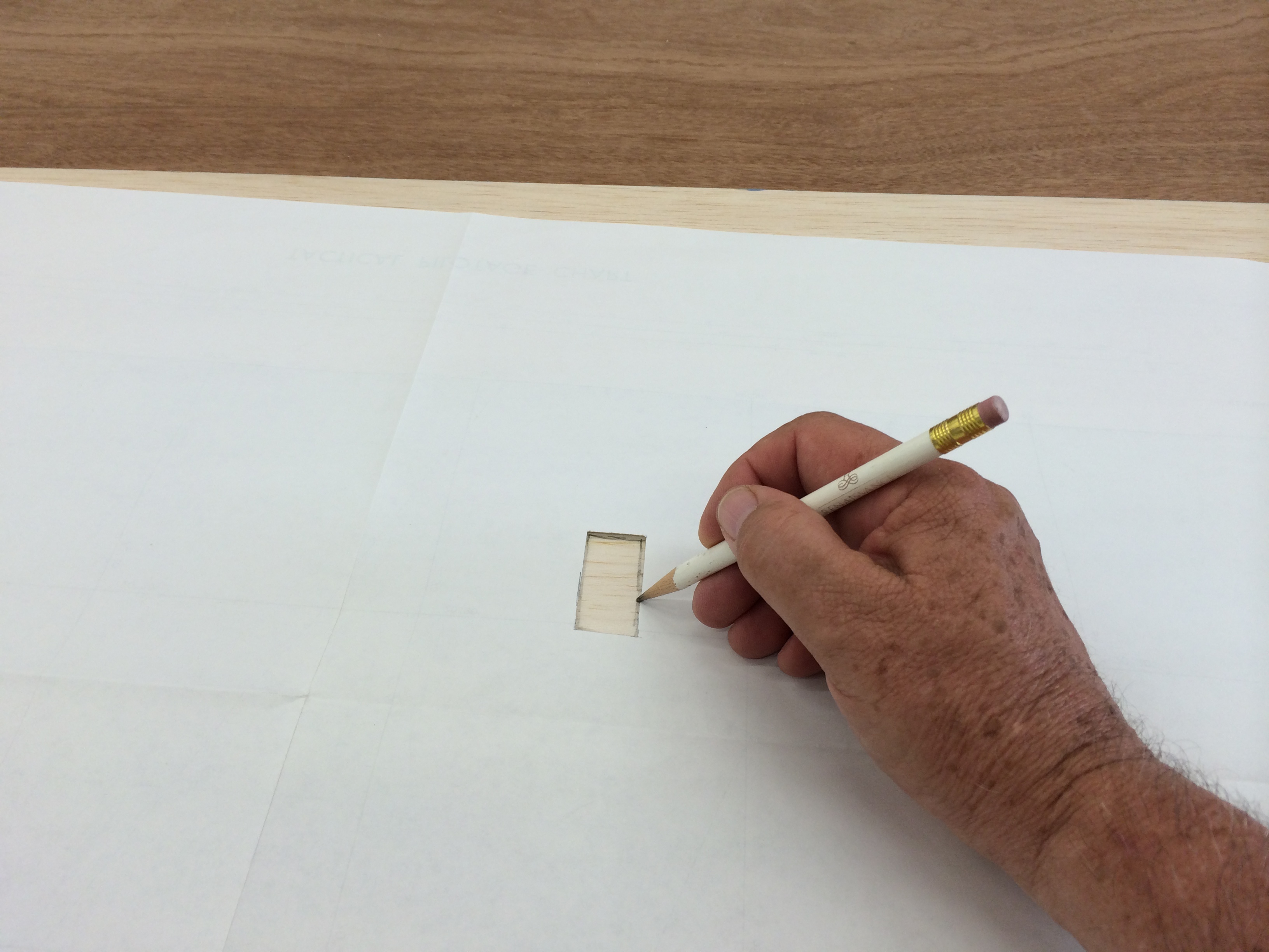
Plotting the wing tip pattern on to 1/8" lite ply
Lightening holes cut in lite ply tipw
Tips sheeted top and bottom with 3/32" sheet balsa
Missile rail patterns plotted on a stack of 3/32" balsa sheet
Rail sides cut out


Missile rails constructed using balsa sticks sandwiched between balsa sheets
Both rails internal structure drying
Wing tip cap pattern traced on lite ply
Wing tip caps cut on scroll saw
Wing tip caps ready for assembly


Screw mounts installed inside rails
Rails drilled for 10-32 flat head mounting bolts
1/4" ply blind nuts mounts installed on inside of wing tip caps
Foam removed to provide relief for blind nut mounts
Wing tip cap dry fit before glue applied
DEC 2014
The next steps were to create double size missile rails and wing tips from Mike Oser's Lancer plans. Since there were no full size plans for this I used some of Gary's freestyle CAD (come along design) TLAR ( that looks about right) to make them up.
Plotting the wing tip pattern on to 1/8" lite ply
Lightening holes cut in lite ply tipw
Tips sheeted top and bottom with 3/32" sheet balsa
Missile rail patterns plotted on a stack of 3/32" balsa sheet
Rail sides cut out
Missile rails constructed using balsa sticks sandwiched between balsa sheets
Both rails internal structure drying
Wing tip cap pattern traced on lite ply
Wing tip caps cut on scroll saw
Wing tip caps ready for assembly
Screw mounts installed inside rails
Rails drilled for 10-32 flat head mounting bolts
1/4" ply blind nuts mounts installed on inside of wing tip caps
Foam removed to provide relief for blind nut mounts
Wing tip cap dry fit before glue applied
Last edited by Viper1GJ; 02-17-2015 at 06:59 PM.
02-17-2015, 06:58 PM
#74
Thread Starter
My Feedback: (20)
Sabre XLT Wing Tips and Rails (cont.)
DEC 2014


Blind nuts tape over to keep glue out of threads
Wing tip caps glued on to wing
Missile rails counter sunk for 10-32 flat head mounting bolts
Wing tips fitted into missile rail slots
Missile rail and tip screwed into wing mounts


Wing tip test fit
The mounting bolts fit well and snug
Tip cap sanded flush with wing skin
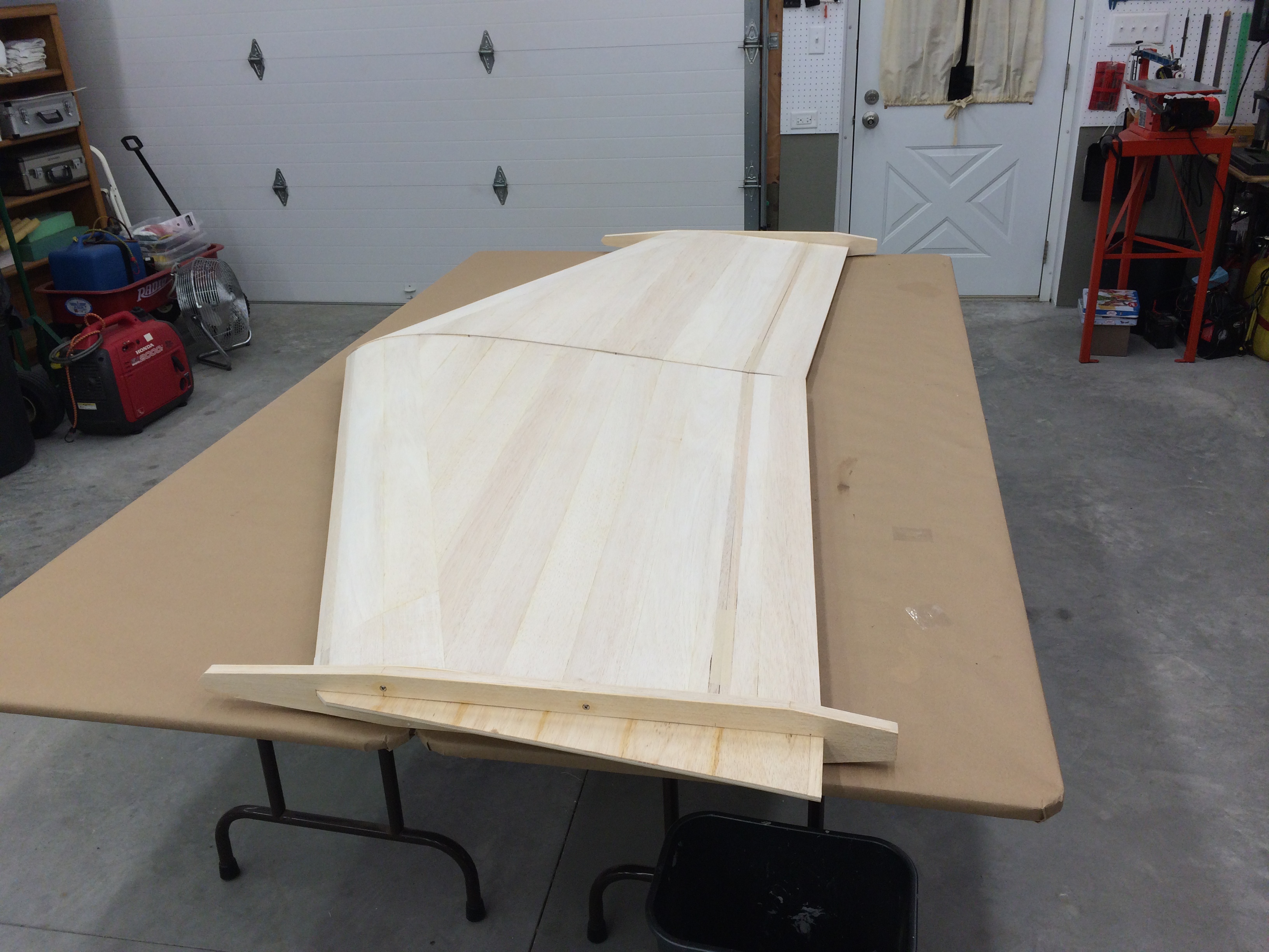
The first look at the whole thing…for reference the table is 5' x 8'...man its really big!
DEC 2014
Blind nuts tape over to keep glue out of threads
Wing tip caps glued on to wing
Missile rails counter sunk for 10-32 flat head mounting bolts
Wing tips fitted into missile rail slots
Missile rail and tip screwed into wing mounts
Wing tip test fit
The mounting bolts fit well and snug
Tip cap sanded flush with wing skin
The first look at the whole thing…for reference the table is 5' x 8'...man its really big!
Last edited by Viper1GJ; 02-17-2015 at 07:01 PM.
03-03-2015, 06:16 PM
#75
Thread Starter
My Feedback: (20)
Sabre XLT Wing Dimensions
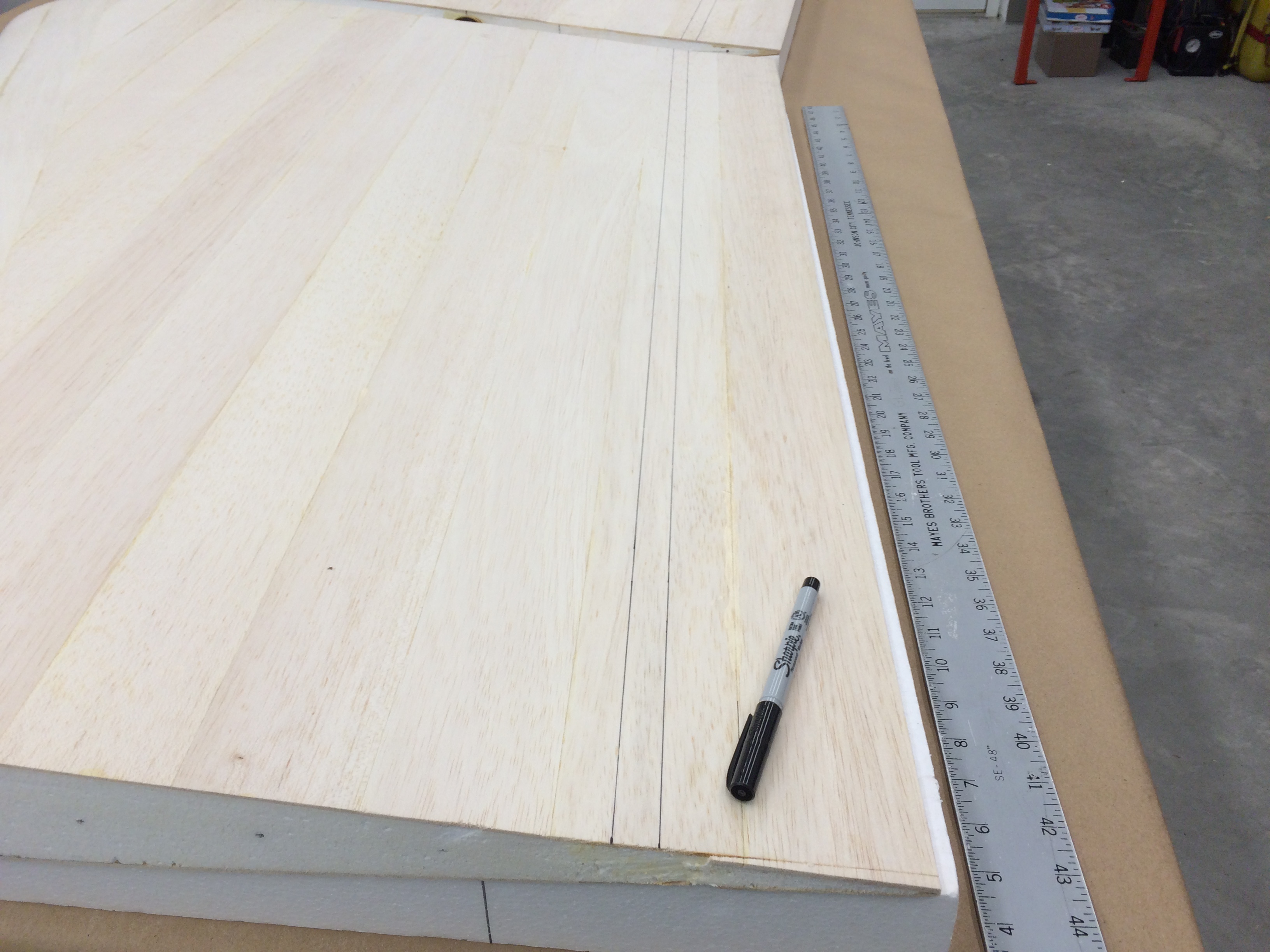
JAN 2015
Mike Oser, the designer of the Lancer and Sabre XLT, ask me to provide him with the exact wing dimensions that I had built. This was because I had slightly altered the size of the wing by adding sheeting to the provided rib patterns, scratch building the tips and adding thicker edge stock to the elevons than planned. Mike needed the exact dimensions to make complex calculations that kept the aircraft neutral point and center of gravity at the proper location relative to the landing gear and over all surface area of the aircraft.


After Mike received the wing dimensions he made the calculations and told me of the changes needed to ensure the Sabre XLT would not just fly but fly well. Mike added to the size of the canard wings on the front of the fuse and reduced the size of the ventral fins on the rear. Also Mike told me we needed to trim the wing tip fin trailing edge forward to the elevon hinge line. All of these changes were to ensure that the neutral point and CG were at the optium point for best performance. The calculations were very complex math but Mike has given me confidence that the Sabre XLT is not just a guess and chance but a well designed aerodynamic balance to get the performance we expected.
Thanks Mike for all your help.
JAN 2015
Mike Oser, the designer of the Lancer and Sabre XLT, ask me to provide him with the exact wing dimensions that I had built. This was because I had slightly altered the size of the wing by adding sheeting to the provided rib patterns, scratch building the tips and adding thicker edge stock to the elevons than planned. Mike needed the exact dimensions to make complex calculations that kept the aircraft neutral point and center of gravity at the proper location relative to the landing gear and over all surface area of the aircraft.
After Mike received the wing dimensions he made the calculations and told me of the changes needed to ensure the Sabre XLT would not just fly but fly well. Mike added to the size of the canard wings on the front of the fuse and reduced the size of the ventral fins on the rear. Also Mike told me we needed to trim the wing tip fin trailing edge forward to the elevon hinge line. All of these changes were to ensure that the neutral point and CG were at the optium point for best performance. The calculations were very complex math but Mike has given me confidence that the Sabre XLT is not just a guess and chance but a well designed aerodynamic balance to get the performance we expected.
Thanks Mike for all your help.