


Sabre XLT – A large scratch built flying wing sport jet
 03-04-2015, 07:00 PM
#76

Thread Starter
My Feedback: (20)
Sabre XLT Shaping Wings and Elevons
JAN 2015
Work continues with shaping the elevon and wing leading edges.


Elevon leading edge shape drawn on wood
Elevon leading edge center line and taper angles
Rough cutting done with Great Planes rotary planer over down draft dust collector table
Final shaping done with 48" Great Planes sanding bar
First look at taper angles
Finish fit of elevon


Leading edge of wings are important to performance of the airfoil design.
Leading edge template transfers leading edge shape to wood
Leading edge center line placed on wood with pins and 48" ruler
Wing in foam shuck weighted on dust table
Rough shaping done with Great Planes rotary planer again


Final wing leading edge shaping done with Great Planes 48" sanding bar again.
Getting close to final shape
Elevons taped in place for the "look see"
Wing leading edge inspection
Good as I could get it
JAN 2015
Work continues with shaping the elevon and wing leading edges.
Elevon leading edge shape drawn on wood
Elevon leading edge center line and taper angles
Rough cutting done with Great Planes rotary planer over down draft dust collector table
Final shaping done with 48" Great Planes sanding bar
First look at taper angles
Finish fit of elevon
Leading edge of wings are important to performance of the airfoil design.
Leading edge template transfers leading edge shape to wood
Leading edge center line placed on wood with pins and 48" ruler
Wing in foam shuck weighted on dust table
Rough shaping done with Great Planes rotary planer again
Final wing leading edge shaping done with Great Planes 48" sanding bar again.
Getting close to final shape
Elevons taped in place for the "look see"
Wing leading edge inspection
Good as I could get it
 03-05-2015, 04:52 PM
#77
Thread Starter
My Feedback: (20)
Sabre XLT Elevon Control Horns
JAN 2015
Elevon control horn hard points installed and drilled


1/4" ply hard point layout on elevon so that ply plate butts up against the elevon leading edge
All four positions marked
Dremel router bit with with 1/4" depth of cut used to remove balsa and foam material so that hard point plate butts against elevon leading edge while shop vacuum sucks away dust
Dry fit of plywood hard point


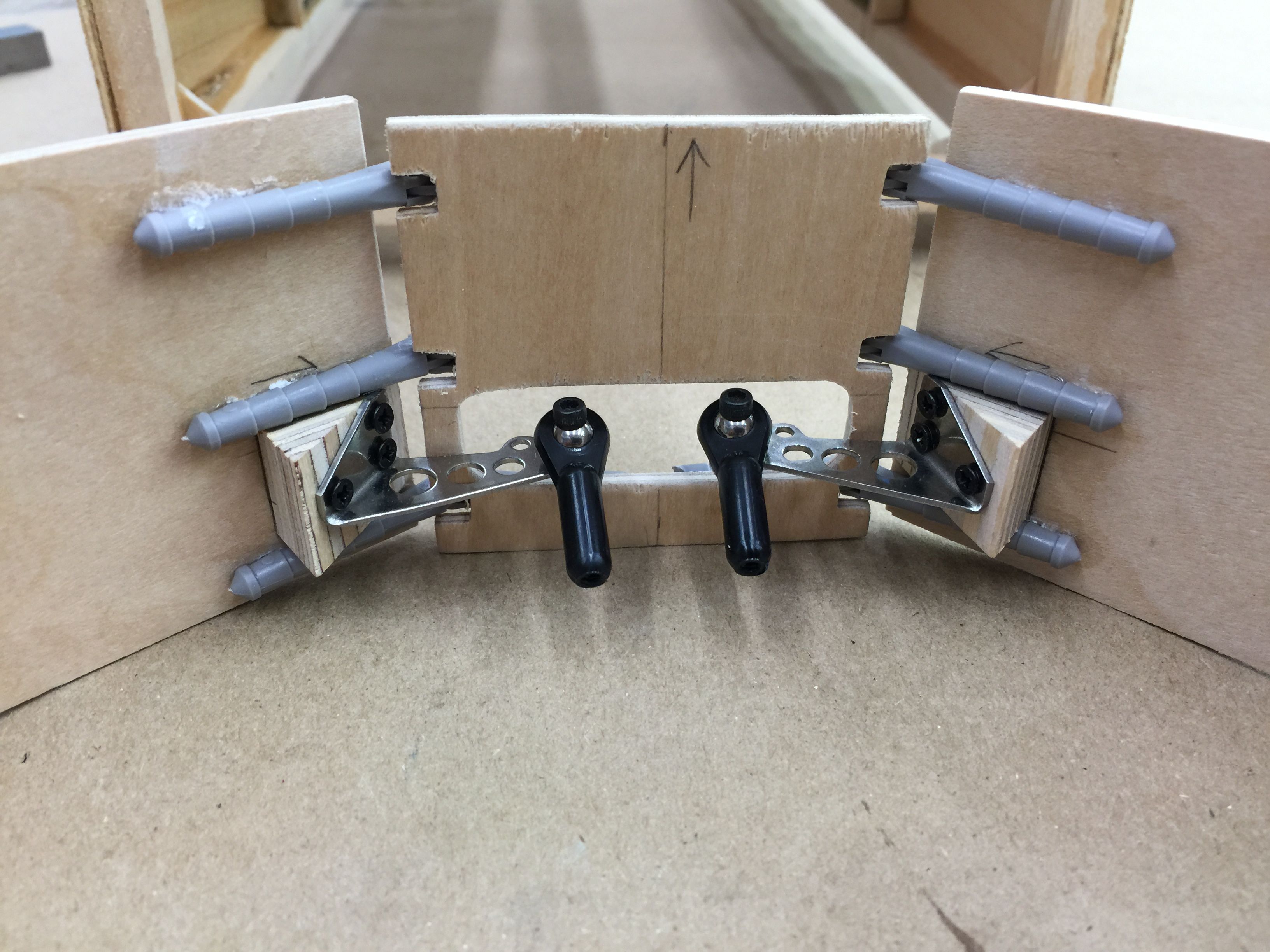
Dry fit of Aeroworks steel double control horns and ball link
All four plates dry fit ready for epoxy
The horn mounting plates are epoxied in place with West Systems resin mixed to a paste with 403 cotton flock to fill all gaps, then carbon fiber cloth laid up over the hard point with straight resin
Plastic sheet laid over the carbon fiber after excess resin removed by blotting with paper towels


Elevons and wings placed back in foam shucks and weighted for curing
After curing and light sanding the control horn mounting hole locations are marked…had to borrow one of my wife's craft pens to find some ink that was visible on the black carbon fiber
Mounting holes pre drilled
Test fit of control horns using servo screws
JAN 2015
Elevon control horn hard points installed and drilled
1/4" ply hard point layout on elevon so that ply plate butts up against the elevon leading edge
All four positions marked
Dremel router bit with with 1/4" depth of cut used to remove balsa and foam material so that hard point plate butts against elevon leading edge while shop vacuum sucks away dust
Dry fit of plywood hard point
Dry fit of Aeroworks steel double control horns and ball link
All four plates dry fit ready for epoxy
The horn mounting plates are epoxied in place with West Systems resin mixed to a paste with 403 cotton flock to fill all gaps, then carbon fiber cloth laid up over the hard point with straight resin
Plastic sheet laid over the carbon fiber after excess resin removed by blotting with paper towels
Elevons and wings placed back in foam shucks and weighted for curing
After curing and light sanding the control horn mounting hole locations are marked…had to borrow one of my wife's craft pens to find some ink that was visible on the black carbon fiber
Mounting holes pre drilled
Test fit of control horns using servo screws
03-05-2015, 05:00 PM
#78
Thread Starter
My Feedback: (20)
Sabre XLT Elevon End Caps
JAN 2015


Elevon ends marked for clearance on each end
Elevon ends trimmed with scroll saw
Balsa end caps traced
Balsa end caps cut out on scroll saw
End caps glued on with wood glue and sanded to shape after dry
JAN 2015
Elevon ends marked for clearance on each end
Elevon ends trimmed with scroll saw
Balsa end caps traced
Balsa end caps cut out on scroll saw
End caps glued on with wood glue and sanded to shape after dry
03-05-2015, 05:28 PM
#79
Thread Starter
My Feedback: (20)
Sabre XLT Wing Root Caps
JAN 2015


Wing tube hole locations transfered from my CAD (come along designed) pencil drawings that were superimposed over Mike Oser's Lancer plans to the light ply wood blank
Wing tube holes drilled out
Tube holes dry fitted to tube sockets on wing root
Wing standing on root rib blank ready for tracing
The wing root cap shape traced on wood blank


Wing root caps cut on scroll saw
Left and right caps ready to install. The wing root cap attachment will wait until I determine the location of the wing mounting bolts after the fuse is built.
At this time the Sabre XLT wings are complete. Final touches will be completed after the fuse is built and the wings can be mated to the fuse.
Unfortunately progress came to a stop after the first week of JAN for about six weeks due to family medical issues.
All is better now and progress was resumed in the last week of FEB.
JAN 2015
Wing tube hole locations transfered from my CAD (come along designed) pencil drawings that were superimposed over Mike Oser's Lancer plans to the light ply wood blank
Wing tube holes drilled out
Tube holes dry fitted to tube sockets on wing root
Wing standing on root rib blank ready for tracing
The wing root cap shape traced on wood blank
Wing root caps cut on scroll saw
Left and right caps ready to install. The wing root cap attachment will wait until I determine the location of the wing mounting bolts after the fuse is built.
At this time the Sabre XLT wings are complete. Final touches will be completed after the fuse is built and the wings can be mated to the fuse.
Unfortunately progress came to a stop after the first week of JAN for about six weeks due to family medical issues.
All is better now and progress was resumed in the last week of FEB.
Last edited by Viper1GJ; 03-05-2015 at 05:34 PM.
03-07-2015, 04:44 AM
#80
Thread Starter
My Feedback: (20)
Sabre XLT Vertical Fin Templates
FEB 2015
Work resumed in late FEB on the vertical fin. During the construction break Mike Oser completed the final CAD drawings for the Sabre XLT fuse. He sent me his final CAD drawings for the fin construction and airfoils to print out on tiled 8.5 X 11" paper.


Vertical fin plans printed out from tiled 8.5 x 11" paper taped together and trimmed
Root and tip airfoil print outs taped together
Foam cutting tabs drawn on leading edge of rib templates
Paper templates ready to use


Spar slots cut out in paper templates to assist in transfer to the foam
Paper patterns spray glue mounted to 1/4" plywood to make foam cutting templates
Templates separated on band saw
Hole drilled in trailing edge centerline prior to final cutting to mount hot wire runoff guide in template


Hot wire runoff guide CA glued into rib templates. This thin wire guide was found not to be stiff enough to support the weight of the cutting wire and bow so next time I will use larger diameter stiffer wire drilled more deeply
Final cutting of airfoil templates on scroll saw
Root template was too long for the throat of the scroll saw so I had to cut it from both the leading edge and trailing edge. Cuts meet here in the photo
Foam cutting airfoil templates after final sanding showing wire runoff guide and leading edge tab


Holes drilled in centerline of template for mounting screws
2" dry wall screws used to mount templates to the foam
1/4" high temp Teflon tape placed on edges of the templates to help hot wire slide over the template. It works great and is very easy to use
Templates ready to use. I found the plywood templates with teflon tape are great for foam cutting and are way easier than making formica or metal templates
FEB 2015
Work resumed in late FEB on the vertical fin. During the construction break Mike Oser completed the final CAD drawings for the Sabre XLT fuse. He sent me his final CAD drawings for the fin construction and airfoils to print out on tiled 8.5 X 11" paper.
Vertical fin plans printed out from tiled 8.5 x 11" paper taped together and trimmed
Root and tip airfoil print outs taped together
Foam cutting tabs drawn on leading edge of rib templates
Paper templates ready to use
Spar slots cut out in paper templates to assist in transfer to the foam
Paper patterns spray glue mounted to 1/4" plywood to make foam cutting templates
Templates separated on band saw
Hole drilled in trailing edge centerline prior to final cutting to mount hot wire runoff guide in template
Hot wire runoff guide CA glued into rib templates. This thin wire guide was found not to be stiff enough to support the weight of the cutting wire and bow so next time I will use larger diameter stiffer wire drilled more deeply
Final cutting of airfoil templates on scroll saw
Root template was too long for the throat of the scroll saw so I had to cut it from both the leading edge and trailing edge. Cuts meet here in the photo
Foam cutting airfoil templates after final sanding showing wire runoff guide and leading edge tab
Holes drilled in centerline of template for mounting screws
2" dry wall screws used to mount templates to the foam
1/4" high temp Teflon tape placed on edges of the templates to help hot wire slide over the template. It works great and is very easy to use
Templates ready to use. I found the plywood templates with teflon tape are great for foam cutting and are way easier than making formica or metal templates
Last edited by Viper1GJ; 03-11-2015 at 05:13 PM.
03-11-2015, 05:40 PM
#81
Thread Starter
My Feedback: (20)
Sabre XLT Vertical Fin Foam Preparation
FEB 2015


Paper template laid out on foam block
Foam cutting guides made from framing squares used to make square cuts
Cut off chunk of foam on floor after cut
Metal drill guide edge used as stand off for the cutting guide because of the extreme angle of the cut


Fin foam block cut out and ready to mount airfoil templates
Center lines marked on top and bottom of foam block
Center line drawn on top
Centerline drawn on bottom


2" drywall screws use to mount cutting template to foam on bottom
Top template screwed to foam
Bottom template mounted showing lead in tab on leading edge and run off wire on trailing edge
Top template in place ready for cutting
FEB 2015
Paper template laid out on foam block
Foam cutting guides made from framing squares used to make square cuts
Cut off chunk of foam on floor after cut
Metal drill guide edge used as stand off for the cutting guide because of the extreme angle of the cut
Fin foam block cut out and ready to mount airfoil templates
Center lines marked on top and bottom of foam block
Center line drawn on top
Centerline drawn on bottom
2" drywall screws use to mount cutting template to foam on bottom
Top template screwed to foam
Bottom template mounted showing lead in tab on leading edge and run off wire on trailing edge
Top template in place ready for cutting
 03-19-2015, 05:05 PM
#83

My Feedback: (123)
Join Date: Jan 2002
Location: Marysville,
WA
Posts: 411
Likes: 0
Received 0 Likes
on
0 Posts
Following this thread/project with great interest! I could see having one that would work for a 28 pound turbine. Maybe call it the Sabre LT.
Bart
Bart
Last edited by b.bixel; 03-19-2015 at 05:07 PM.
06-02-2015, 10:38 AM
#84
Thread Starter
My Feedback: (20)
Sabre XLT Vertical Fin Foam Cutting
MAR 2015


Swing arm cutter and bow ready for setup
Swing arm cutter attached to edge of work table
Cutting bow suspension rope and wires suspended from ceiling fixture
Auto cutting system setup and ready to test


Fin tip template and cutting wire ready to cut after multiple dry runs to adjust the attachment points on the swing arms
Final setup ready to cut
First cut in progress on tip template
First cut complete and acceptable, some small ripples due to hot wore exiting tip early and trying to manually hold it to allow root cut to exit the foam
Ropes reversed on swing arms and ready for second cut


Final cut complete and acceptable
Fin foam core inspected and slightly sanded with a bar sander and ready for spars
MAR 2015
Swing arm cutter and bow ready for setup
Swing arm cutter attached to edge of work table
Cutting bow suspension rope and wires suspended from ceiling fixture
Auto cutting system setup and ready to test
Fin tip template and cutting wire ready to cut after multiple dry runs to adjust the attachment points on the swing arms
Final setup ready to cut
First cut in progress on tip template
First cut complete and acceptable, some small ripples due to hot wore exiting tip early and trying to manually hold it to allow root cut to exit the foam
Ropes reversed on swing arms and ready for second cut
Final cut complete and acceptable
Fin foam core inspected and slightly sanded with a bar sander and ready for spars
06-02-2015, 11:13 AM
#85
Thread Starter
My Feedback: (20)
Sabre XLT Vertical Fin Spars
MAR 2015


Fin spar slots laid out on foam core
Four layers of masking tape used to form hot wire cutting templates
Hot wire cutter in spar slot
1/4" ply spar slot test fit
Removing tape cutting templates after cuts made


Fin foam core sanded and rudder hinge line marked out
Fin spar blanks drilled for lightening holes
Fin spars ready for gluing
Fin spars installed with polyurethane glue and tape, glue still foamed out of tape
Glue squeeze out from joints


Tape removed and glue foam sanded off
Fin core ready for carbon fiber
MAR 2015
Fin spar slots laid out on foam core
Four layers of masking tape used to form hot wire cutting templates
Hot wire cutter in spar slot
1/4" ply spar slot test fit
Removing tape cutting templates after cuts made
Fin foam core sanded and rudder hinge line marked out
Fin spar blanks drilled for lightening holes
Fin spars ready for gluing
Fin spars installed with polyurethane glue and tape, glue still foamed out of tape
Glue squeeze out from joints
Tape removed and glue foam sanded off
Fin core ready for carbon fiber
06-02-2015, 11:22 AM
#86
Thread Starter
My Feedback: (20)
Sabre XLT Vertical Fin Carbon Fiber
MAR 2015


Carbon uni tape laid out on foam core
Carbon fiber laid out over spars
Opposite side carbon lay out
Plastic sheet cut for epoxy lamination separation


Carbon laminated with West Systems epoxy and weighted for curing
Plastic sheet removed after curing
Fin ready for balsa sheeting
MAR 2015
Carbon uni tape laid out on foam core
Carbon fiber laid out over spars
Opposite side carbon lay out
Plastic sheet cut for epoxy lamination separation
Carbon laminated with West Systems epoxy and weighted for curing
Plastic sheet removed after curing
Fin ready for balsa sheeting
06-02-2015, 11:34 AM
#87
Thread Starter
My Feedback: (20)
Sabre XLT Fuse Formers
MAR 2015
Mike Oser sent me the final CAD drawings for the fuse formers. I printed them out on 8.5 x 11" pages and prepared to start cutting fuse formers.


Former patterns printed out on paper
Former patterns cut down for gluing to wood
Former patterns laid out on plywood, plywood blanks cut out on table saw
Former patterns laid out on plywood blanks
Paper patterns spray glued to plywood blanks and ready for cutting


Let the scroll saw cutting begin…
Wood parts labeled for identification after paper is removed
Multiple same parts cut in a stack on scroll saw
Stack parts after cutting
Wood formers cut and ready for assembly
MAR 2015
Mike Oser sent me the final CAD drawings for the fuse formers. I printed them out on 8.5 x 11" pages and prepared to start cutting fuse formers.
Former patterns printed out on paper
Former patterns cut down for gluing to wood
Former patterns laid out on plywood, plywood blanks cut out on table saw
Former patterns laid out on plywood blanks
Paper patterns spray glued to plywood blanks and ready for cutting
Let the scroll saw cutting begin…
Wood parts labeled for identification after paper is removed
Multiple same parts cut in a stack on scroll saw
Stack parts after cutting
Wood formers cut and ready for assembly
10-18-2015, 06:03 PM
#88
Thread Starter
My Feedback: (20)
Sabre XLT Cutting Fuse Sides
SEP 2015
For anybody following this thread there was a 6 month work stop on the Sabre XLT project for the summer flying season and attending RC fly-ins and jet meets. There is one more jet meet this year to attend next week here in Lake City, SC. After that I hope to continue the Sabre project until finished. I will never again forecast when the finish will be since we are going on 3 years, it will be when it will be. I have enjoyed several weeks of building and it is starting to look like an airplane. Here are the latest work photos starting in SEP 2015.


Mike Oser's CAD produced fuse layout showing dimensions to transfer to the wood
I used 3/32 basswood plywood for the fuse panels. This was purchased in a 4' x 8' sheet from Aircraft Spruce and Speciality in Peachtree, GA
Fuse side blanks laid out on plywood
Table saw cuts for the fuse sides
Fuse side blanks cut
Fuse plans laid out on the wood


Freehand table saw cuts for tapered fuse edges
Wing tube hole locations transfered to sides from wing root rib pattern
Cutting wing tube holes
Cutting air intake corner holes
Cutting air intake hole sides
Finished fuse side panels
SEP 2015
For anybody following this thread there was a 6 month work stop on the Sabre XLT project for the summer flying season and attending RC fly-ins and jet meets. There is one more jet meet this year to attend next week here in Lake City, SC. After that I hope to continue the Sabre project until finished. I will never again forecast when the finish will be since we are going on 3 years, it will be when it will be. I have enjoyed several weeks of building and it is starting to look like an airplane. Here are the latest work photos starting in SEP 2015.
Mike Oser's CAD produced fuse layout showing dimensions to transfer to the wood
I used 3/32 basswood plywood for the fuse panels. This was purchased in a 4' x 8' sheet from Aircraft Spruce and Speciality in Peachtree, GA
Fuse side blanks laid out on plywood
Table saw cuts for the fuse sides
Fuse side blanks cut
Fuse plans laid out on the wood
Freehand table saw cuts for tapered fuse edges
Wing tube hole locations transfered to sides from wing root rib pattern
Cutting wing tube holes
Cutting air intake corner holes
Cutting air intake hole sides
Finished fuse side panels
Last edited by Viper1GJ; 10-18-2015 at 06:50 PM.
10-18-2015, 06:11 PM
#89
Thread Starter
My Feedback: (20)
Sabre XLT Framing Fuse Sides
SEP 2015


Fuse sides edge framed with 3/8 x 3/8 bass wood sticks
Carbon fibre tubes added over and under air intake holes to provide support for tail mounted engine
Wing tube doublers glued in place
Engine mount doublers glued in place


Engine mount wings dry fitted
Fuse sides ready to assemble
SEP 2015
Fuse sides edge framed with 3/8 x 3/8 bass wood sticks
Carbon fibre tubes added over and under air intake holes to provide support for tail mounted engine
Wing tube doublers glued in place
Engine mount doublers glued in place
Engine mount wings dry fitted
Fuse sides ready to assemble
10-18-2015, 06:31 PM
#90
Thread Starter
My Feedback: (20)
Sabre XLT Joining Fuse Sides
SEP 2015


Fuse cross beam cut from 3/8 x 3/8 basswood sticks
Best building board I ever use for scratch building is the Magnetic Building board
Board was produced by EJ Lind several years ago. It has been invaluable for my scratch built projects
Foam blocks cut the the correct size used for fuse jigs to stand up the side and hold them square
Everything came out straight and square. I was amazed. It rarely does.
Frame glue up started at the rear end.


Wood clamps used to hold sides together during glue up
Foam blocks removed as cross beams glued in
Plywood gussets cut on scroll saw
Basswood gussets cut on scroll saw
Plywood and basswood gussets applied on each corner joint


Fuse stood on nose and tail to assist in running a glue fillet on each joint
Nose ring former glued in using square and clamps. This former was supposed to have a 1.5 degree nose down tilt that I forgot. I will correct the angle when adding the nose cone.
Clamps used to draw the front sides together as nose tapers to front nose ring former
Finish fuse after glue up
SEP 2015
Fuse cross beam cut from 3/8 x 3/8 basswood sticks
Best building board I ever use for scratch building is the Magnetic Building board
Board was produced by EJ Lind several years ago. It has been invaluable for my scratch built projects
Foam blocks cut the the correct size used for fuse jigs to stand up the side and hold them square
Everything came out straight and square. I was amazed. It rarely does.
Frame glue up started at the rear end.
Wood clamps used to hold sides together during glue up
Foam blocks removed as cross beams glued in
Plywood gussets cut on scroll saw
Basswood gussets cut on scroll saw
Plywood and basswood gussets applied on each corner joint
Fuse stood on nose and tail to assist in running a glue fillet on each joint
Nose ring former glued in using square and clamps. This former was supposed to have a 1.5 degree nose down tilt that I forgot. I will correct the angle when adding the nose cone.
Clamps used to draw the front sides together as nose tapers to front nose ring former
Finish fuse after glue up
10-18-2015, 06:48 PM
#91
Thread Starter
My Feedback: (20)
Sabre XLT Fuse Bottom
SEP 2015


Bottom fuse formers installed
Nose curves will be covered with balsa strips
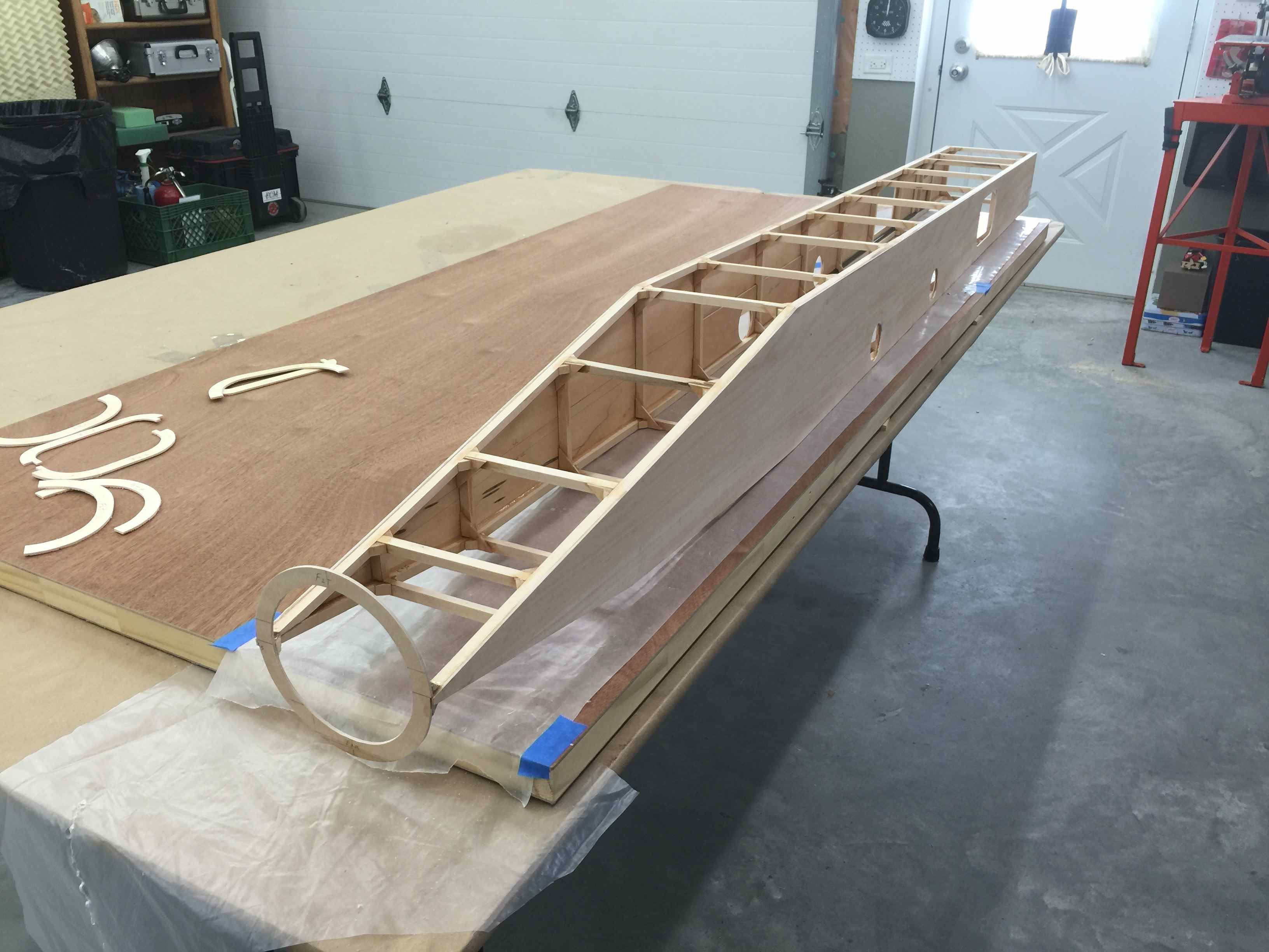
Size of fuse against the garage door
Bottom panel marked for cutting
Bottom panel cut
Bottom panel installed to formers


Fuse bottom corner strips cut from 1/8" balsa sheet
Balsa strips glued to formers at the corner
Balsa strips applied to formers on the bottom nose
Bottom nose complete
Almost closed in
Engine access hatch parts ready to install


Engine access hatch assembled. Side rails of hatch are 3/32 basswood plywood
Access hatch bottom panel installed
Hatch ready for balsa strips
Balsa strips glued on
Finished turbine engine hatch
SEP 2015
Bottom fuse formers installed
Nose curves will be covered with balsa strips
Size of fuse against the garage door
Bottom panel marked for cutting
Bottom panel cut
Bottom panel installed to formers
Fuse bottom corner strips cut from 1/8" balsa sheet
Balsa strips glued to formers at the corner
Balsa strips applied to formers on the bottom nose
Bottom nose complete
Almost closed in
Engine access hatch parts ready to install
Engine access hatch assembled. Side rails of hatch are 3/32 basswood plywood
Access hatch bottom panel installed
Hatch ready for balsa strips
Balsa strips glued on
Finished turbine engine hatch
10-19-2015, 03:11 AM
#92
Thread Starter
My Feedback: (20)
Sabre XLT Fuse Top Hatches
SEP 2015


Notching top hatch formers
Former side rails taped to fuse and framing square used to hold top hatch formers in place
Top hatch formers glued in
Top hatch panel glued in place


Front hatch side rail shape traced on to the plywood and cut out
Shaped hatch side rails taped to fuse
Framing square used again to hold formers in place for gluing
Front hatch top plank glued in place
Front and rear fuse hatches framed up


Hatches frames on fuse
Fuse starting to take shape
Correcting a build mistake. Rear former removed from rear hatch to form swept back shape to allow hatch to be removed easily.
SEP 2015
Notching top hatch formers
Former side rails taped to fuse and framing square used to hold top hatch formers in place
Top hatch formers glued in
Top hatch panel glued in place
Front hatch side rail shape traced on to the plywood and cut out
Shaped hatch side rails taped to fuse
Framing square used again to hold formers in place for gluing
Front hatch top plank glued in place
Front and rear fuse hatches framed up
Hatches frames on fuse
Fuse starting to take shape
Correcting a build mistake. Rear former removed from rear hatch to form swept back shape to allow hatch to be removed easily.
10-19-2015, 05:03 PM
#93
Thread Starter
My Feedback: (20)
Sabre XLT Top Planking and Hatch Pins
OCT 2015


Drilling holes for front hatch locking pins
Fron hatch pins dry fit
Rear hatch pin brackets
Front hatch sheeting starting with rear hatch pins engaged
Left side sheeting applied
Right side sheeting almost done


Front sheeting glued on
Rear hatch sheeting started
Rear hatch left side sheeting taped in place
Rear hatch locking pins engages in front bracket
Rear hatch right side sheeting taped in place
Sheeting complete


Left side view
Hatches removed
Happy snaps to see the over shape taking place. For motivation only.
Rear hatch has a slight twist after removing tape.


Blocked up and weighted after sprayed with 50/50 water and alcohol mix to remove twist
Rear hatch alignment pins
Rear hatch locking pins to front hatch
Front hatch locking pins in nose former
OCT 2015
Drilling holes for front hatch locking pins
Fron hatch pins dry fit
Rear hatch pin brackets
Front hatch sheeting starting with rear hatch pins engaged
Left side sheeting applied
Right side sheeting almost done
Front sheeting glued on
Rear hatch sheeting started
Rear hatch left side sheeting taped in place
Rear hatch locking pins engages in front bracket
Rear hatch right side sheeting taped in place
Sheeting complete
Left side view
Hatches removed
Happy snaps to see the over shape taking place. For motivation only.
Rear hatch has a slight twist after removing tape.
Blocked up and weighted after sprayed with 50/50 water and alcohol mix to remove twist
Rear hatch alignment pins
Rear hatch locking pins to front hatch
Front hatch locking pins in nose former
10-19-2015, 05:14 PM
#94
Thread Starter
My Feedback: (20)
Sabre XLT Rudder Servo Mount
OCT 2015


Plywood rudder servo mount plate
Doublers on back of servo plate for screws
Plate location traced on foam core
Hot wire cutter set for depth of cut for servo plate
Foam removed for servo plate
Depth of cut set to remove foam for servo well


Rudder servo plate dry fit
1/2" aluminum tube sharpened with notches in cutting end used for servo wire channel core drill
Core drill tube cut through to servo well
Servo wire dry fit
Balsa fillers around servo flush with foam surface for sheeting
OCT 2015
Plywood rudder servo mount plate
Doublers on back of servo plate for screws
Plate location traced on foam core
Hot wire cutter set for depth of cut for servo plate
Foam removed for servo plate
Depth of cut set to remove foam for servo well
Rudder servo plate dry fit
1/2" aluminum tube sharpened with notches in cutting end used for servo wire channel core drill
Core drill tube cut through to servo well
Servo wire dry fit
Balsa fillers around servo flush with foam surface for sheeting
10-19-2015, 05:39 PM
#95
Thread Starter
My Feedback: (20)
Sabre XLT Fin Sheeting
OCT 2015


3/32" balsa sheeting planks laid out
Both skins taped together
Edges sanded straight
CA thin glue used to attach sheets
First skin almost complete
Both skins glue up complete
Skins sanded on down draft dust collection table with 220 grit and 320 grit paper


Very important skin map marked and cut to find rudder servo well after sheeting
Paper map complete
Vacuum bagging breather cloth and separator plastic prepared
Skins trailing edge taped together
Blue tape added to keep trailing edge tape from detaching
Skins booked together for dry fit to core
Fin core dry fit to skins


 \
\
Skins folded over foam core in dry fit
Practice stacking of bagging materials
Air nipples attached to top plastic sheet
During dry fit I found the plastic sheets slid around so clear packing tape on foam shucks kept things together. Valuable lesson learned in dry practice run
Cores stacked on breather cloth and separater sheets
Everything ready to apply glue to inside of skins and place in vacuum bag
Polyurethane glue has been applied to skins and folded over cores, cores placed between plastic sheets and caulk used to seal edges. Vacuum pump turned on


Vacuum bag sealed up and holding
Pump set for 7psi
Cores removed from vacuum bag after 8 hours, looks good
Fin Root looks good, good glue bond all the way around
Overall good outcome from bag
Fin tip and leading edge showing good glue bond
Fin root looks good
OCT 2015
3/32" balsa sheeting planks laid out
Both skins taped together
Edges sanded straight
CA thin glue used to attach sheets
First skin almost complete
Both skins glue up complete
Skins sanded on down draft dust collection table with 220 grit and 320 grit paper
Very important skin map marked and cut to find rudder servo well after sheeting
Paper map complete
Vacuum bagging breather cloth and separator plastic prepared
Skins trailing edge taped together
Blue tape added to keep trailing edge tape from detaching
Skins booked together for dry fit to core
Fin core dry fit to skins
Skins folded over foam core in dry fit
Practice stacking of bagging materials
Air nipples attached to top plastic sheet
During dry fit I found the plastic sheets slid around so clear packing tape on foam shucks kept things together. Valuable lesson learned in dry practice run
Cores stacked on breather cloth and separater sheets
Everything ready to apply glue to inside of skins and place in vacuum bag
Polyurethane glue has been applied to skins and folded over cores, cores placed between plastic sheets and caulk used to seal edges. Vacuum pump turned on
Vacuum bag sealed up and holding
Pump set for 7psi
Cores removed from vacuum bag after 8 hours, looks good
Fin Root looks good, good glue bond all the way around
Overall good outcome from bag
Fin tip and leading edge showing good glue bond
Fin root looks good
10-20-2015, 05:15 PM
#96
Thread Starter
My Feedback: (20)
Sabre XLT Rudder and Fin Edging
OCT 2015


Fin tip edge sanded on down draft dust collection table
Fin root cleaned up
Fin leading edge cleaned up
Fin core after edge sanding
Fin layout map in place to mark rudder servo mount


Rudder servo mount marked
Rudder cutout marked
Rudder cutout cut on scroll saw
Rudder separated from fin
Rudder leading edge separated
Rudder and fin balsa edging glued in place


Fin leading edge shaped with power planer
Edges sanded to shape
Rudder leading edge shape marked
Rudder leading edge shaped
Rudder leading edge finished


Fin leading edge sanded to shape
Finished rudder and fin after sanding to shape and rudder servo mount trimmed out
Rudder control horn mount epoxied in place
Rudder control horn laminated with carbon fiber
Weighting during epoxy cure
OCT 2015
Fin tip edge sanded on down draft dust collection table
Fin root cleaned up
Fin leading edge cleaned up
Fin core after edge sanding
Fin layout map in place to mark rudder servo mount
Rudder servo mount marked
Rudder cutout marked
Rudder cutout cut on scroll saw
Rudder separated from fin
Rudder leading edge separated
Rudder and fin balsa edging glued in place
Fin leading edge shaped with power planer
Edges sanded to shape
Rudder leading edge shape marked
Rudder leading edge shaped
Rudder leading edge finished
Fin leading edge sanded to shape
Finished rudder and fin after sanding to shape and rudder servo mount trimmed out
Rudder control horn mount epoxied in place
Rudder control horn laminated with carbon fiber
Weighting during epoxy cure
10-20-2015, 05:38 PM
#97
Thread Starter
My Feedback: (20)
Sabre XLT Fuse Top Rear Formers
OCT 2015


Top rear formers cut ready for dry fit
Top rear formers and top beams dry fit
Fin spars dry fit into formers
Clamps holding formers into position under fin spars
Dry fit good ready for former glue up


Top rear formers epoxy into position
F13 squared up during glue up
Fin held down by tape during epoxy cure
Fuse starting to show airplane shape
Top rear formers after epoxy cure
Marking top plank for spar slot cutting


Fin spar slots cut in top plank
Fin dry fit into slots. Top plank will not be glued in until all engine, speed brake, thrust vector item are installed
OCT 2015
Top rear formers cut ready for dry fit
Top rear formers and top beams dry fit
Fin spars dry fit into formers
Clamps holding formers into position under fin spars
Dry fit good ready for former glue up
Top rear formers epoxy into position
F13 squared up during glue up
Fin held down by tape during epoxy cure
Fuse starting to show airplane shape
Top rear formers after epoxy cure
Marking top plank for spar slot cutting
Fin spar slots cut in top plank
Fin dry fit into slots. Top plank will not be glued in until all engine, speed brake, thrust vector item are installed
10-20-2015, 05:49 PM
#98
Thread Starter
My Feedback: (20)
Sabre XLT Engine Dry Fit
OCT 2015


Thrust vector nozzle fit to K-180G turbine. Steel straps between turbine mount and nozzle mount keep nozzle from sliding off back of turbine case
Engine dry fit into fuse
TV servos will be mounted below engine with pushrods running to ball joints on nozzle
Nozzle will extend slightly aft of fuse when fiberglass tail pipe ring is installed
Mounting holes drilled and blind nuts installed looking from top
Engine mount viewed from bottom of fuse
OCT 2015
Thrust vector nozzle fit to K-180G turbine. Steel straps between turbine mount and nozzle mount keep nozzle from sliding off back of turbine case
Engine dry fit into fuse
TV servos will be mounted below engine with pushrods running to ball joints on nozzle
Nozzle will extend slightly aft of fuse when fiberglass tail pipe ring is installed
Mounting holes drilled and blind nuts installed looking from top
Engine mount viewed from bottom of fuse
12-06-2015, 03:21 PM
#99
Thread Starter
My Feedback: (20)
Sabre XLT Speed Brake Build
OCT 2015


Paper patterns from plan blow up on vertical fin
Balsa faring and plywood speed brake parts cut
Speedbrake rear view
Speedbrake panels and Robart hinges


Robart hinges in speedbrake bulkhead notches
Hinge dry fit and tac glue with CA
Trial operation and dry fit to fuse


Sanding forward faring for speed brake clearance
Hinges on front of bulkhead
Speed brake control horns dry fit
Balsa faring rough sanded
OCT 2015
Paper patterns from plan blow up on vertical fin
Balsa faring and plywood speed brake parts cut
Speedbrake rear view
Speedbrake panels and Robart hinges
Robart hinges in speedbrake bulkhead notches
Hinge dry fit and tac glue with CA
Trial operation and dry fit to fuse
Sanding forward faring for speed brake clearance
Hinges on front of bulkhead
Speed brake control horns dry fit
Balsa faring rough sanded
Last edited by Viper1GJ; 12-06-2015 at 06:39 PM.
12-06-2015, 03:29 PM
#100
Thread Starter
My Feedback: (20)
Sabre XLT Speed Brake Horns and Epoxy
OCT 2015


Speedbrake control horn mounts
Speedbrake dry fit with ball joints on horns
Rudder TE sanded for control horn clearance


Final speed brake dry fit
Robart hinges epoxied in with Loctite marine epoxy similar to Hysol


FInal epoxy done
Final fit to fuse
OCT 2015
Speedbrake control horn mounts
Speedbrake dry fit with ball joints on horns
Rudder TE sanded for control horn clearance
Final speed brake dry fit
Robart hinges epoxied in with Loctite marine epoxy similar to Hysol
FInal epoxy done
Final fit to fuse
Last edited by Viper1GJ; 12-06-2015 at 06:44 PM.