


VIXEN - virtual build thread
 07-01-2015, 06:16 AM
#1

Thread Starter
Join Date: Jan 2007
Location: farnborough, , UNITED KINGDOM
Posts: 3,294
Likes: 0
Received 1 Like
on
1 Post
The VIXEN is a new sports jet, a collaboration between myself and Xtreme ARF, its a sharp looking modern sports jet manufactured using the latest composite technology.
The VIXEN has been test flown in the USA before a final 'production' spec model was built, this is the first of these and incorporates all the changes and feedback given by the pilot, builder and myself.
The specs are:
Length 2667mm (105")
Span 2388 (94")
AUW expected 18-20kg
Turbine 180+
The original thread is found here http://www.rcuniverse.com/forum/rc-j...ming-soon.html
Two videos of the test flying are here https://www.youtube.com/watch?v=xl7caO1uMMc
Some key features of the VIXEN are:
Split fuselage aft of wings to make a compact transportation format.
Removable fin, one piece stab and wings
Notched wing leading edge
Swept wing tips
Hard points in wings for ordinance/drop tanks
Trailing ling landing gear
Fitted wheel wells
Belly mounted dive brake
Painted outside of the mould to customer specified colour scheme
It's been a long while since a did a build thread on RCU so I'm going to be rusty, the VIXEN is being built as my demo kit and I hope to build and have it test flown here in the UK in time to fly it at Jetpower in September. I'm happy that a friend and top notch pilot will be flying the Vixen - 'Azza' Aaron Stephens.
The VIXEN is in final paint prep currently so I won't have the kit until late next week (hopefully) but wanted to start the post with a hardware choice.
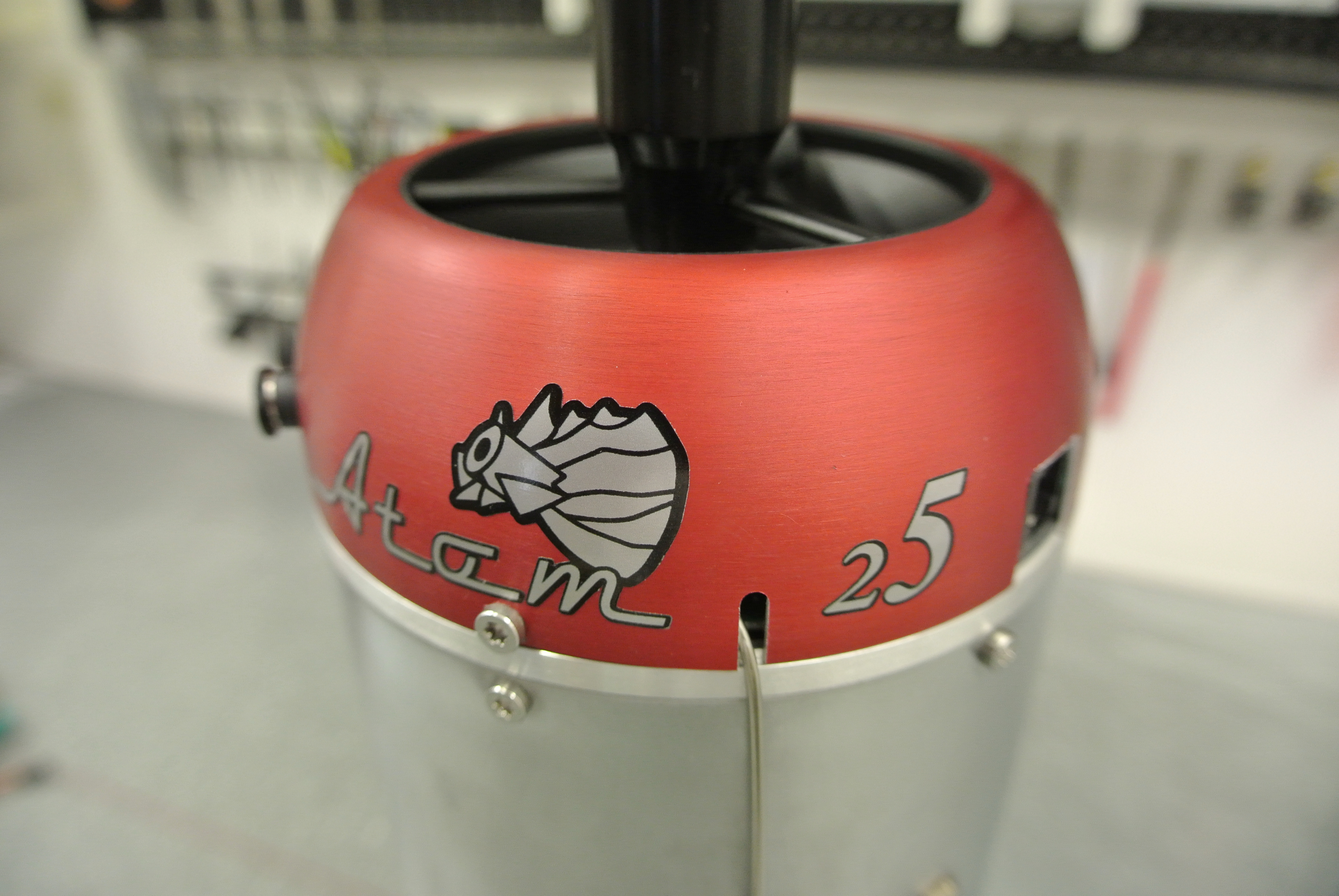
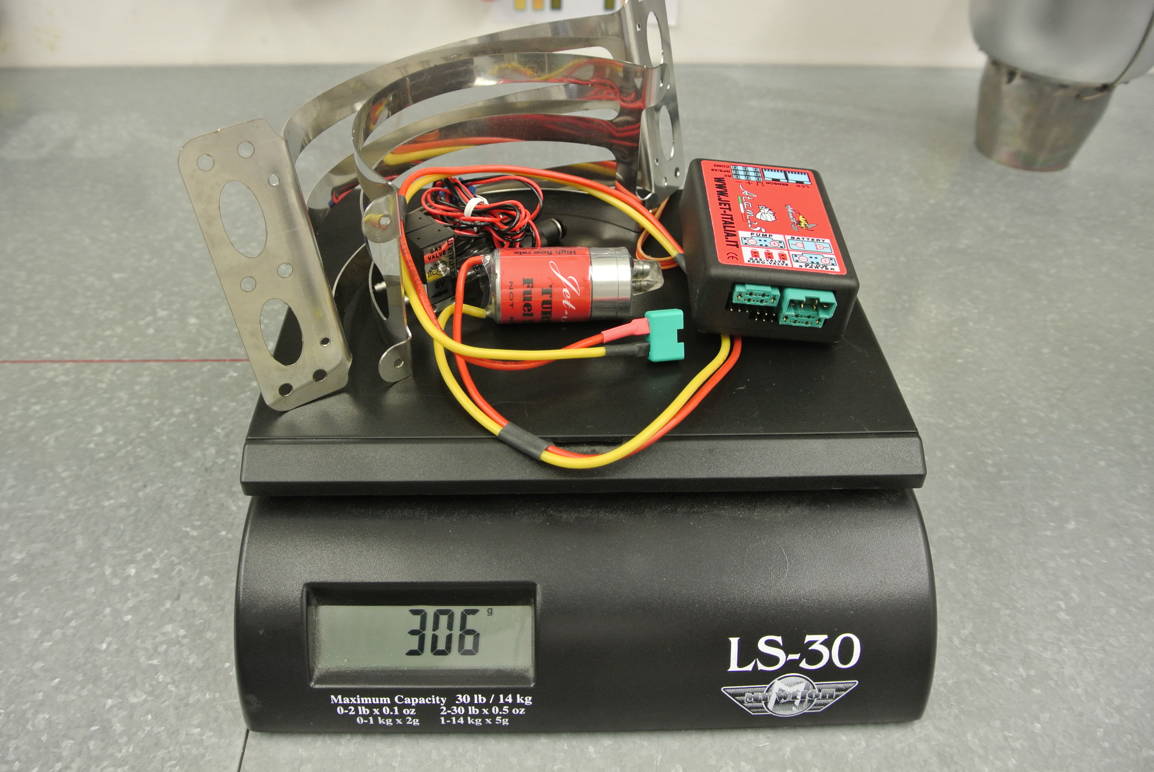
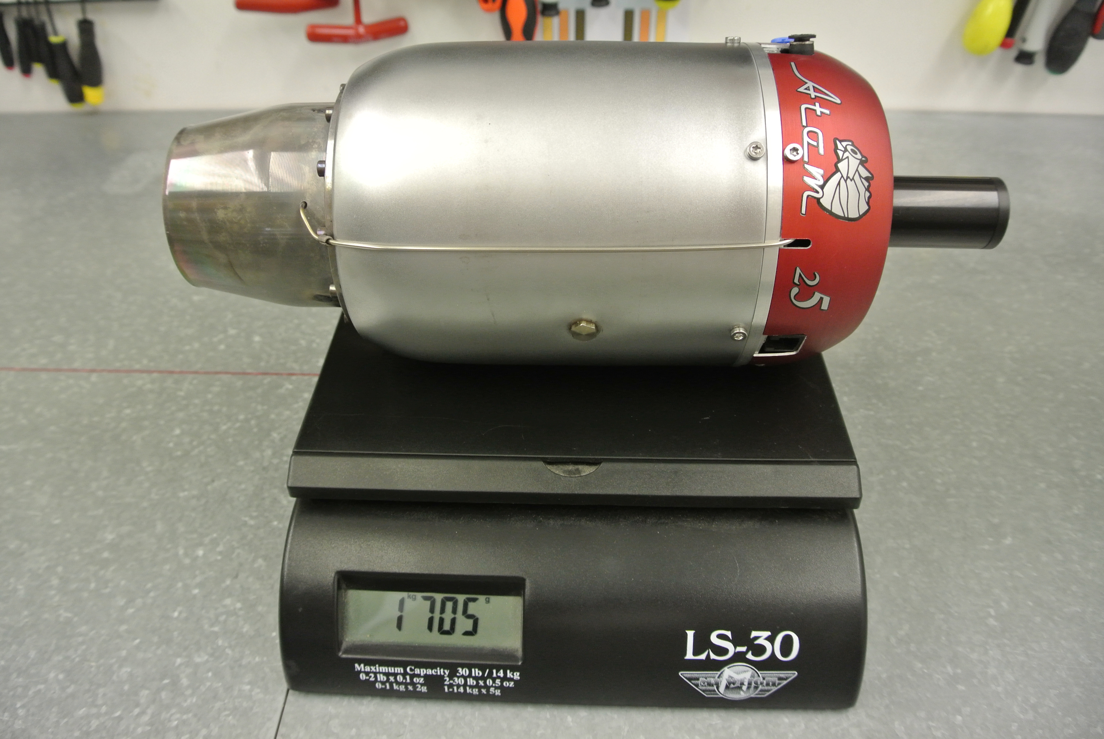
Today the turbine arrived, it's the new Jet Italia Atom 250, a very compact and light turbine which delivers a big punch in the 'newton' field, my friend Francesco has worked hard to build and ship me this turbine so that I can test and fit this gem of engineering into the VIXEN.
I chose the Atom 250 as it looked to provide exactly what I wanted in a lightweight and compact package.
Attached are some pictures of the Atom 250 and look forward to the results it delivers when the build is complete. More to follow.
marcs
The VIXEN has been test flown in the USA before a final 'production' spec model was built, this is the first of these and incorporates all the changes and feedback given by the pilot, builder and myself.
The specs are:
Length 2667mm (105")
Span 2388 (94")
AUW expected 18-20kg
Turbine 180+
The original thread is found here http://www.rcuniverse.com/forum/rc-j...ming-soon.html
Two videos of the test flying are here https://www.youtube.com/watch?v=xl7caO1uMMc
Some key features of the VIXEN are:
Split fuselage aft of wings to make a compact transportation format.
Removable fin, one piece stab and wings
Notched wing leading edge
Swept wing tips
Hard points in wings for ordinance/drop tanks
Trailing ling landing gear
Fitted wheel wells
Belly mounted dive brake
Painted outside of the mould to customer specified colour scheme
It's been a long while since a did a build thread on RCU so I'm going to be rusty, the VIXEN is being built as my demo kit and I hope to build and have it test flown here in the UK in time to fly it at Jetpower in September. I'm happy that a friend and top notch pilot will be flying the Vixen - 'Azza' Aaron Stephens.
The VIXEN is in final paint prep currently so I won't have the kit until late next week (hopefully) but wanted to start the post with a hardware choice.
Today the turbine arrived, it's the new Jet Italia Atom 250, a very compact and light turbine which delivers a big punch in the 'newton' field, my friend Francesco has worked hard to build and ship me this turbine so that I can test and fit this gem of engineering into the VIXEN.
I chose the Atom 250 as it looked to provide exactly what I wanted in a lightweight and compact package.
Attached are some pictures of the Atom 250 and look forward to the results it delivers when the build is complete. More to follow.
marcs
 07-07-2015, 07:41 AM
#3
Thread Starter
Join Date: Jan 2007
Location: farnborough, , UNITED KINGDOM
Posts: 3,294
Likes: 0
Received 1 Like
on
1 Post
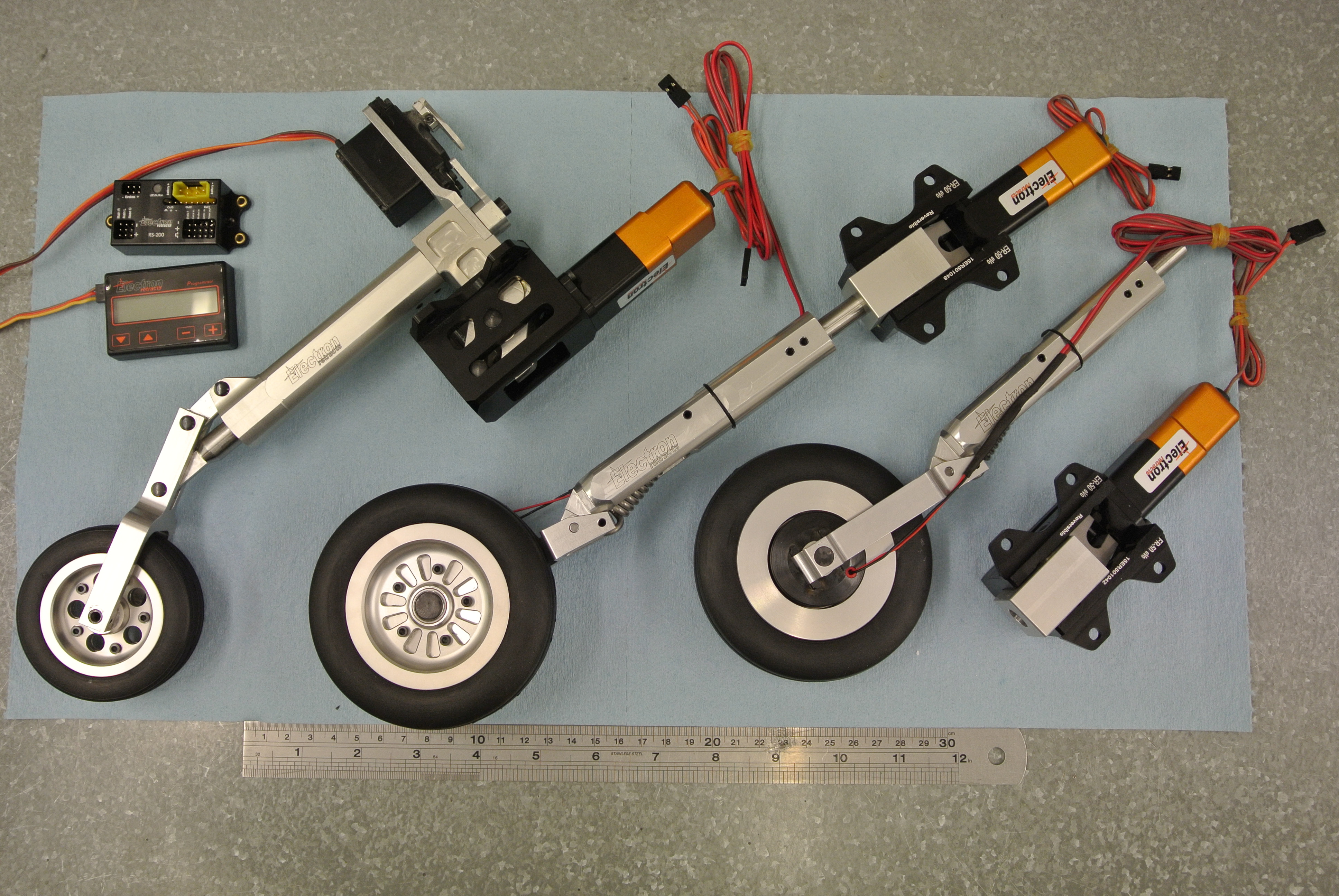
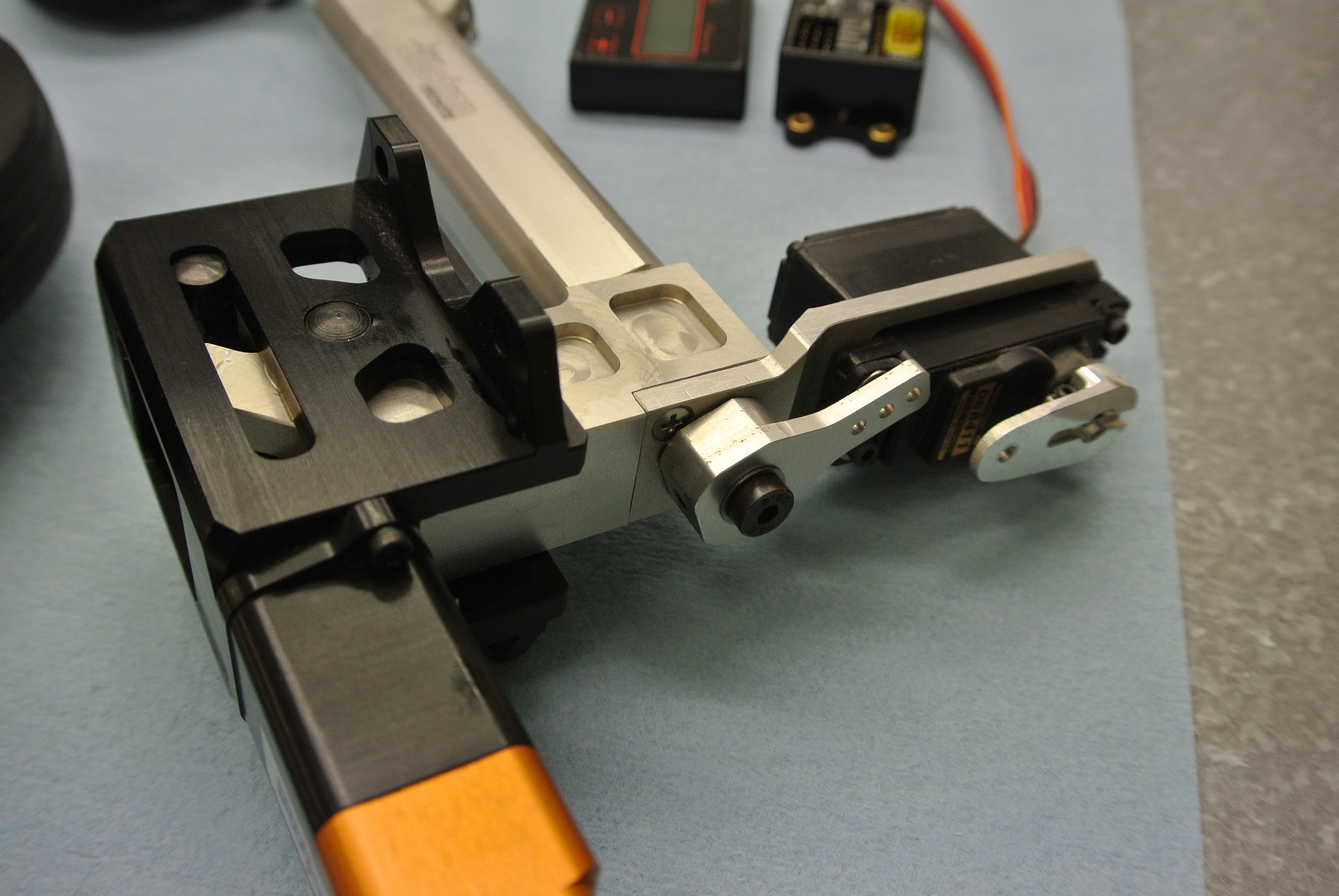
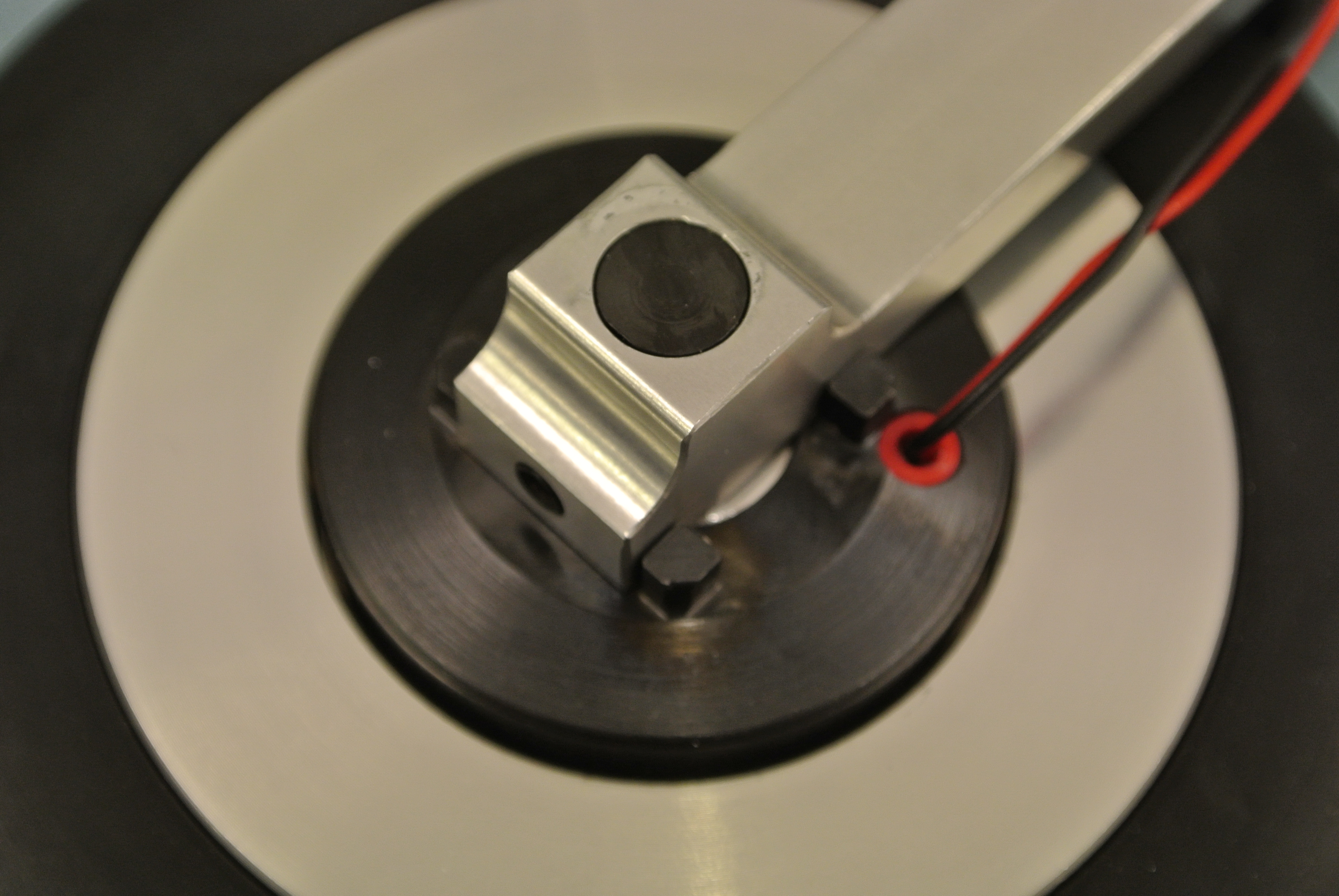
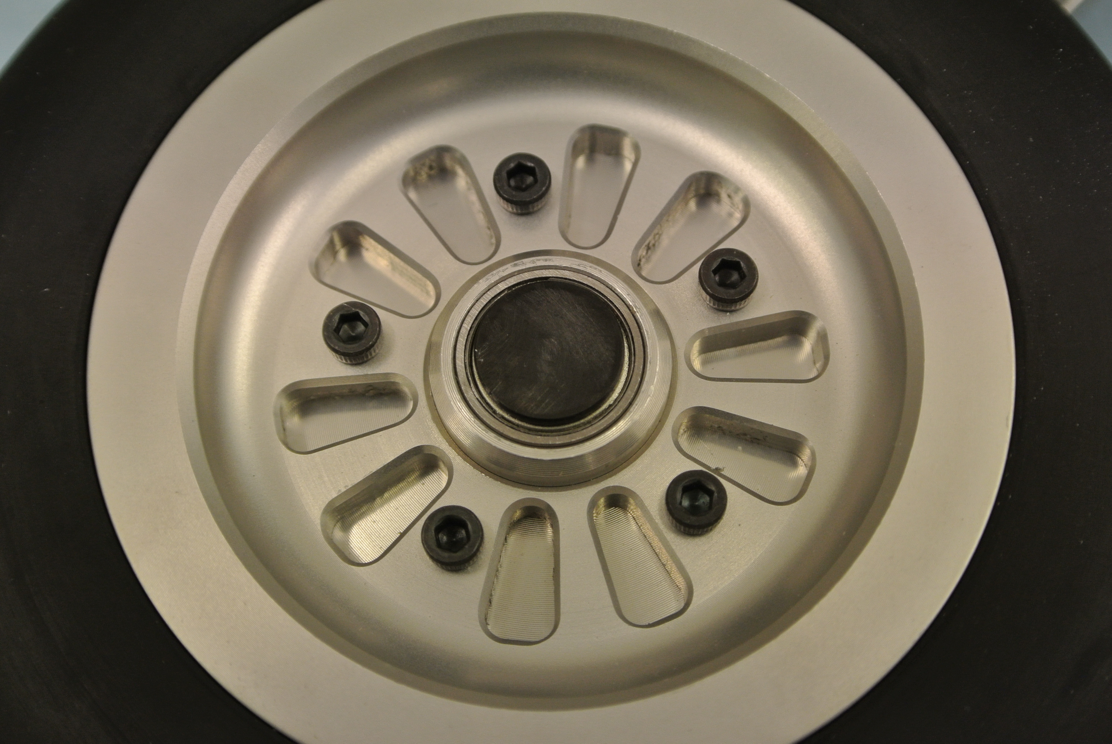
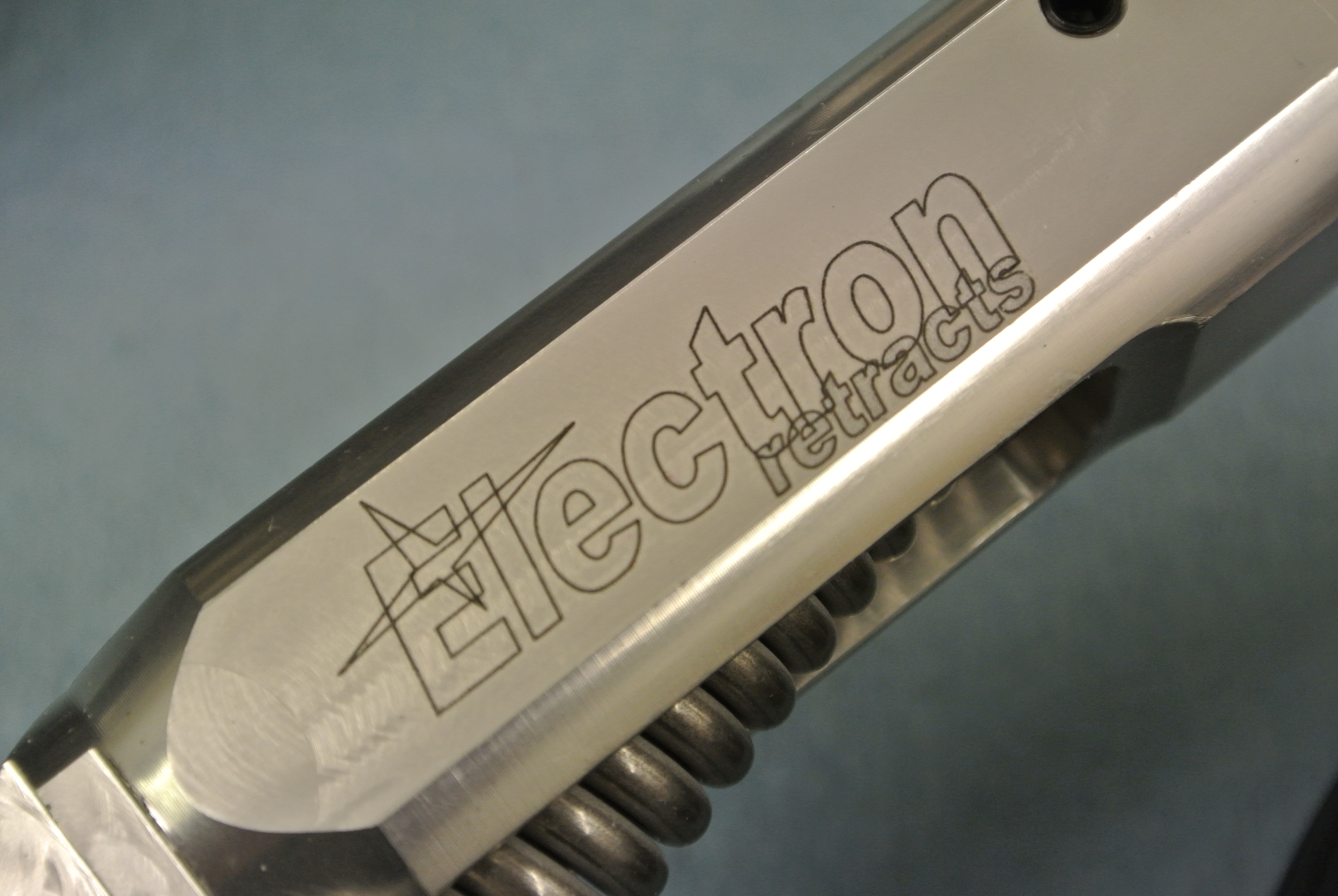
The Vixen is now in final paint prep and should be packed and shipped later this week, whilst this is going on I have received a set of custom made Electron Retracts to test and ultimately offer as an 'electric' option for the Vixen kit.
Big thanks to Xoel for working with me on this and machining special legs and parts for the retract units to get them to the right configuration.
There will be an amount of 'adapting' mainly on the gear rails to hopefully get these to fit so the final results wont be known until I have the airframe with me.
I've never been a great fan of air, electric tick more boxes for me and having had very good experiences with Electron on past models the choice was a simple one for me and I'm glad Xoel has agreed to work with me on this.
Quality is really top notch, the feel gives you confidence in the durability and robustness and all the machining is beautifully finished. In addition I have the R200 controller and programming pad to set things up and the mains are running the Electron electric brakes.
A few pics of the gear supplied for testing....
marcs
07-14-2015, 09:36 AM
#4
Thread Starter
Join Date: Jan 2007
Location: farnborough, , UNITED KINGDOM
Posts: 3,294
Likes: 0
Received 1 Like
on
1 Post
The demo kit is painted and on it's way to the UK, really hope it arrives safe and sound....
As soon as it lands I will start the build and keep you all updated.
marcs
As soon as it lands I will start the build and keep you all updated.
marcs

The following users liked this post:
Jetmodeler (03-01-2021)
07-14-2015, 07:32 PM
#9
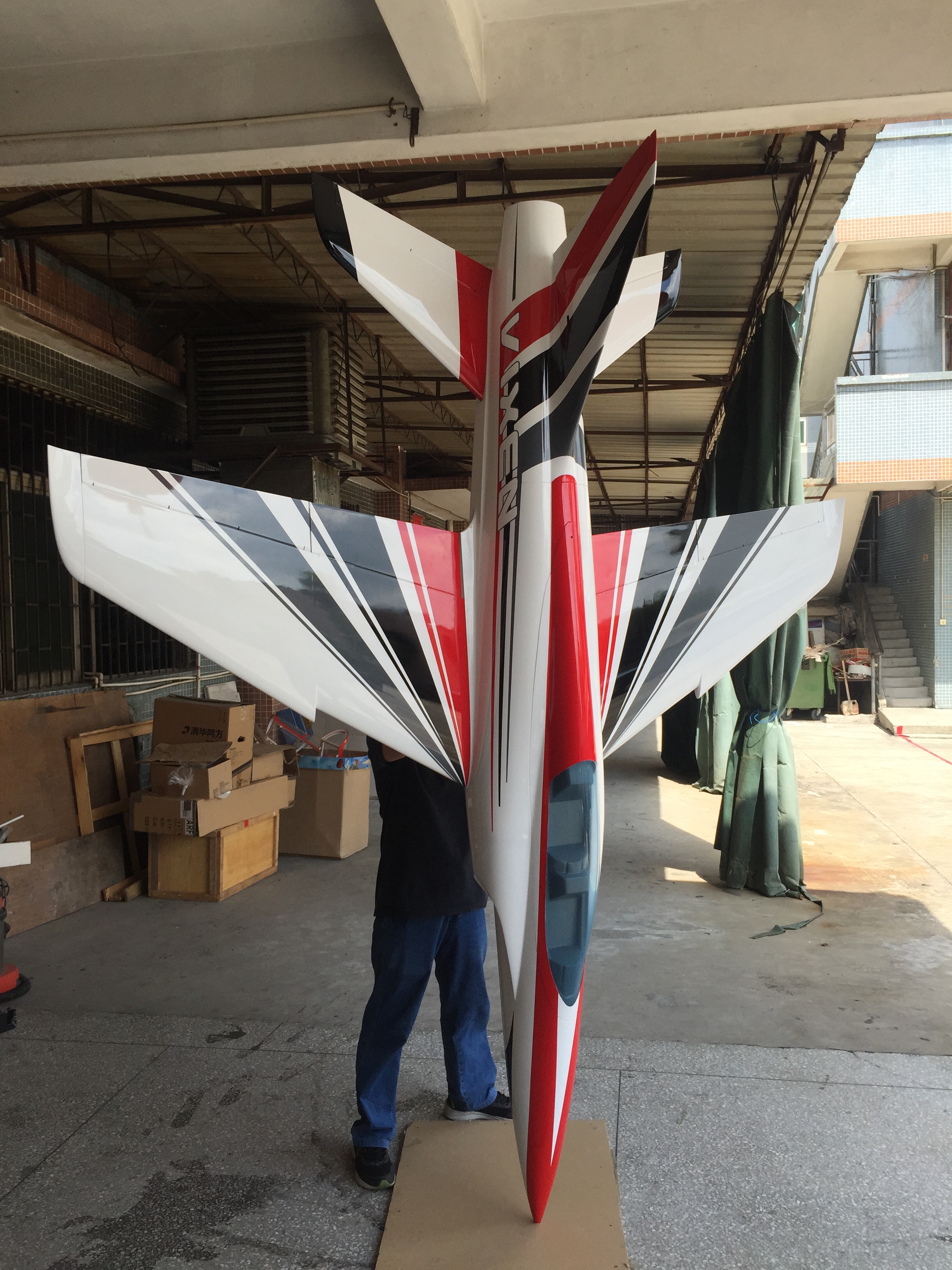
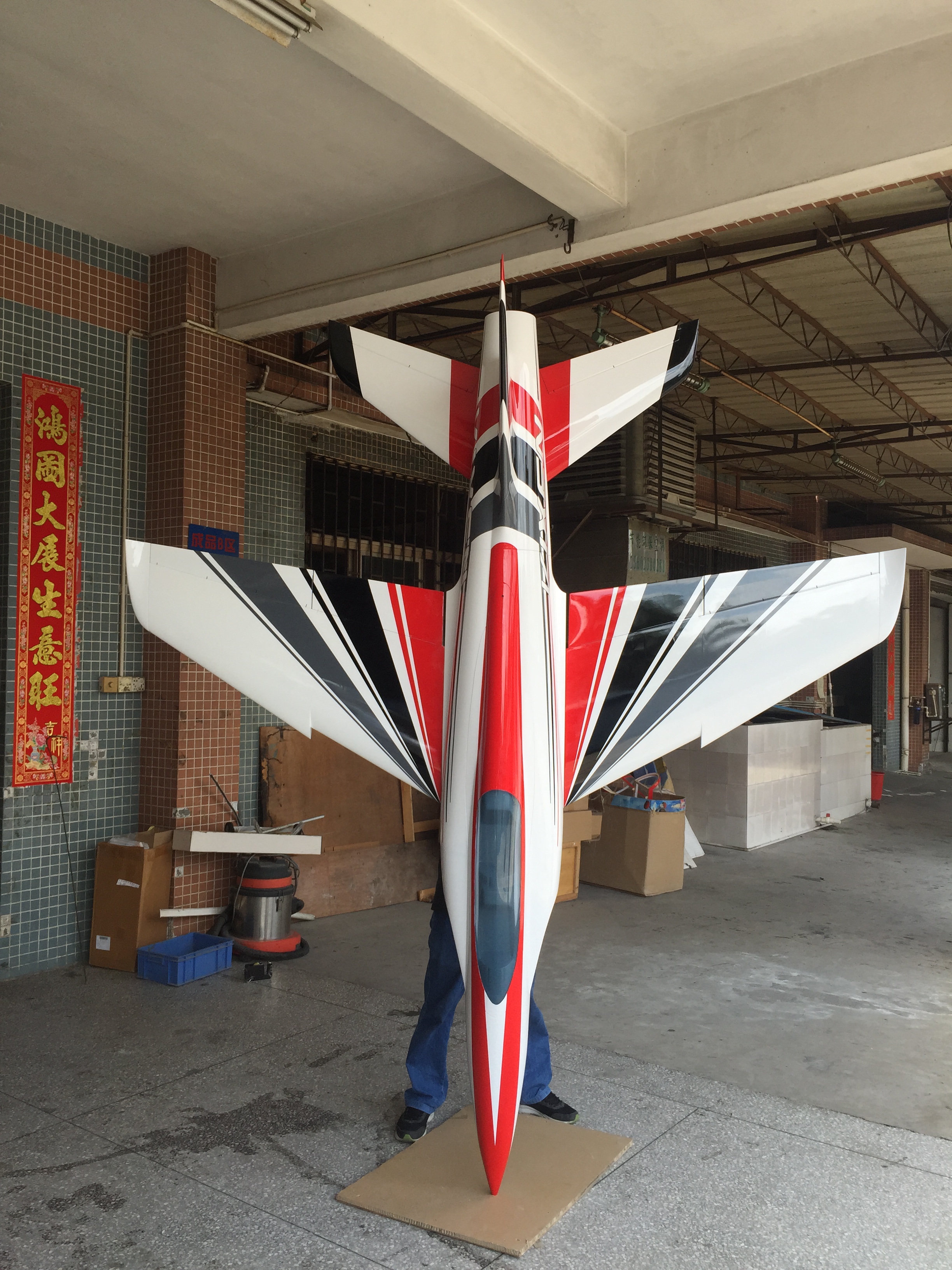
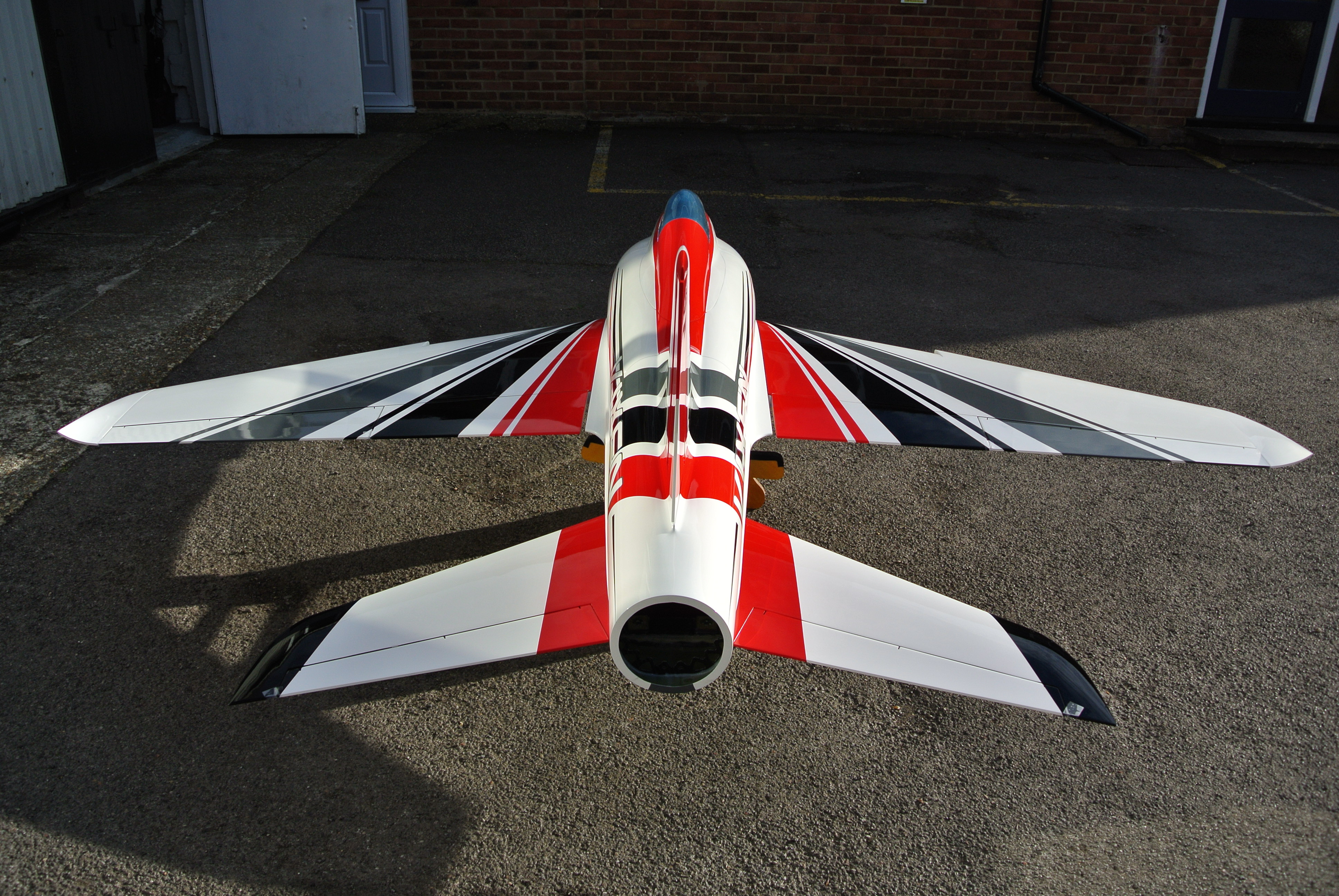
A little more pictures from Marc's Vixen
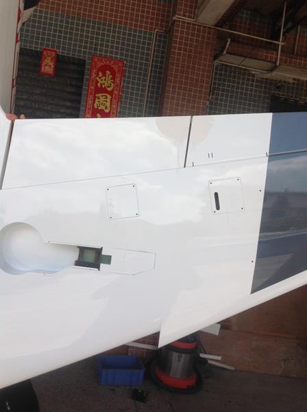
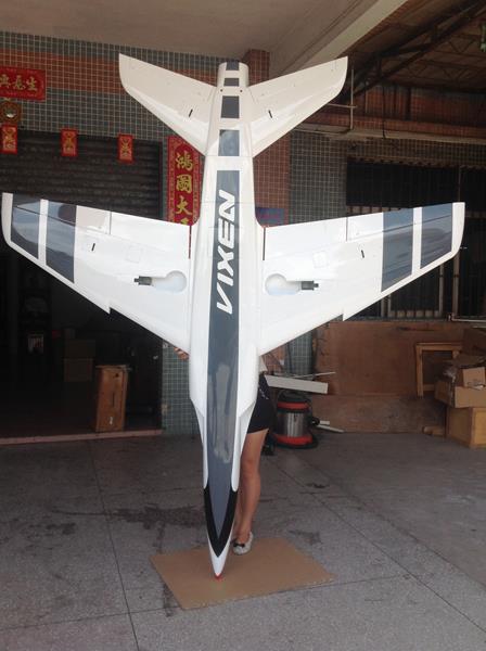
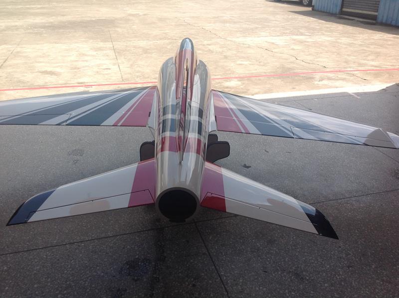
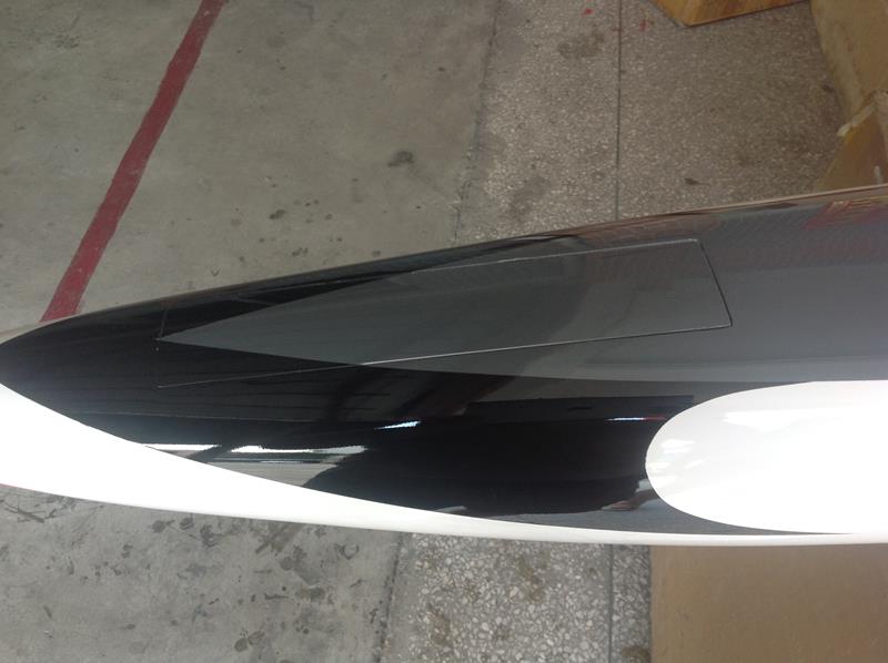
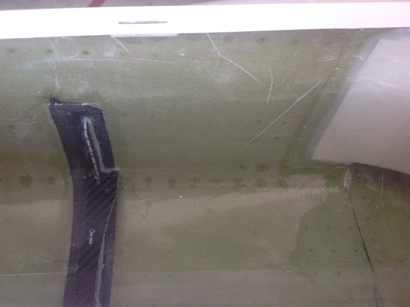
The first picture shows the flaps linkage are internal, the second is the bottom of the color scheme, third is the back, fourth is the nose door gear installation and finishing (hinges are aluminum) and last one is the reinforcement (all the plane are reinforced with carbon fiber but did not show once it is done before the Airex layer), now all formers has an extra stripe of carbon fiber before installation.
The first picture shows the flaps linkage are internal, the second is the bottom of the color scheme, third is the back, fourth is the nose door gear installation and finishing (hinges are aluminum) and last one is the reinforcement (all the plane are reinforced with carbon fiber but did not show once it is done before the Airex layer), now all formers has an extra stripe of carbon fiber before installation.
07-22-2015, 10:44 AM
#10
Thread Starter
Join Date: Jan 2007
Location: farnborough, , UNITED KINGDOM
Posts: 3,294
Likes: 0
Received 1 Like
on
1 Post
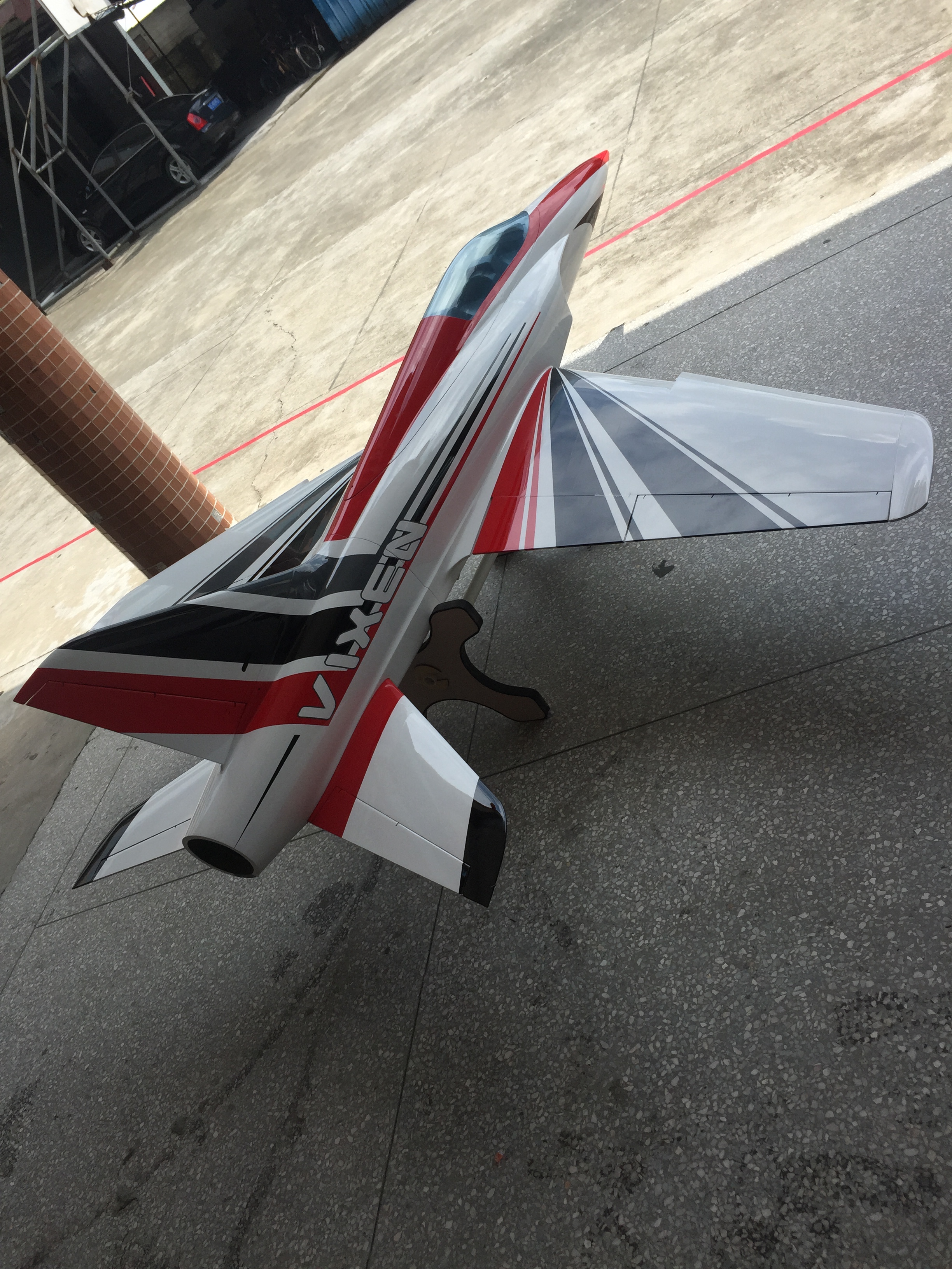
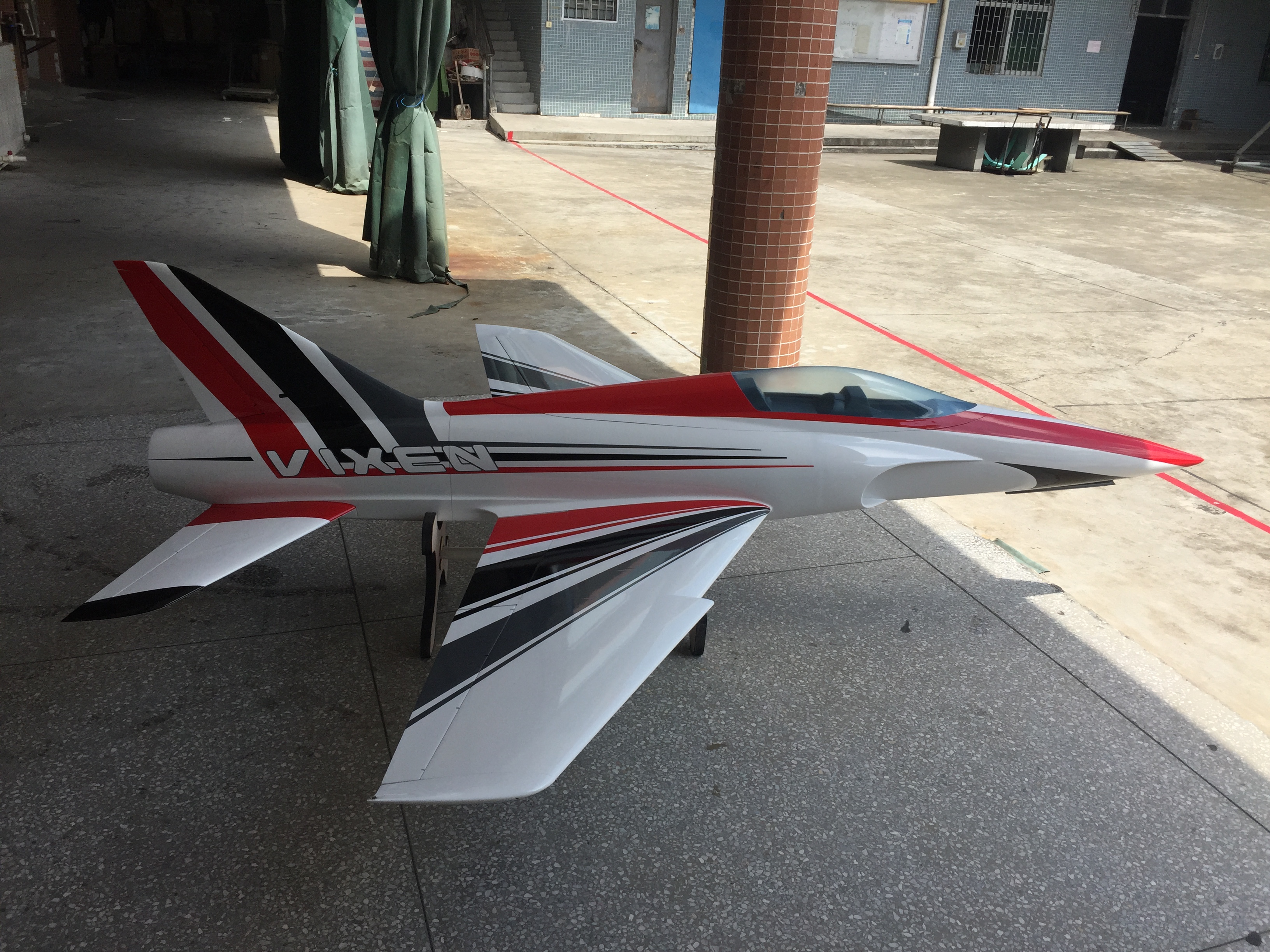
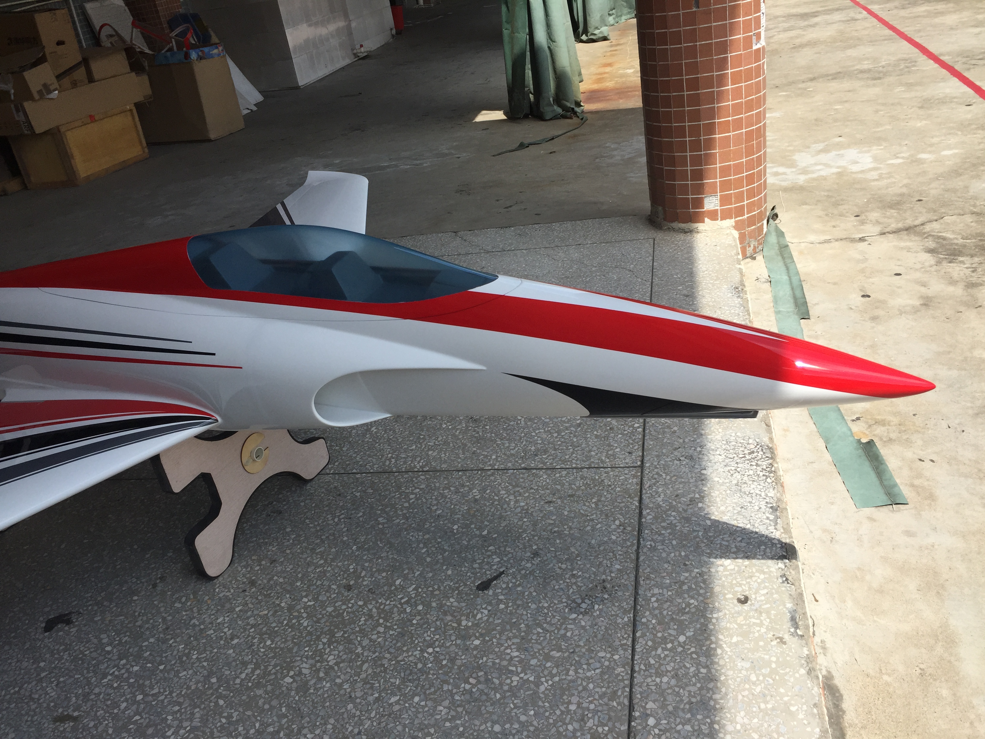
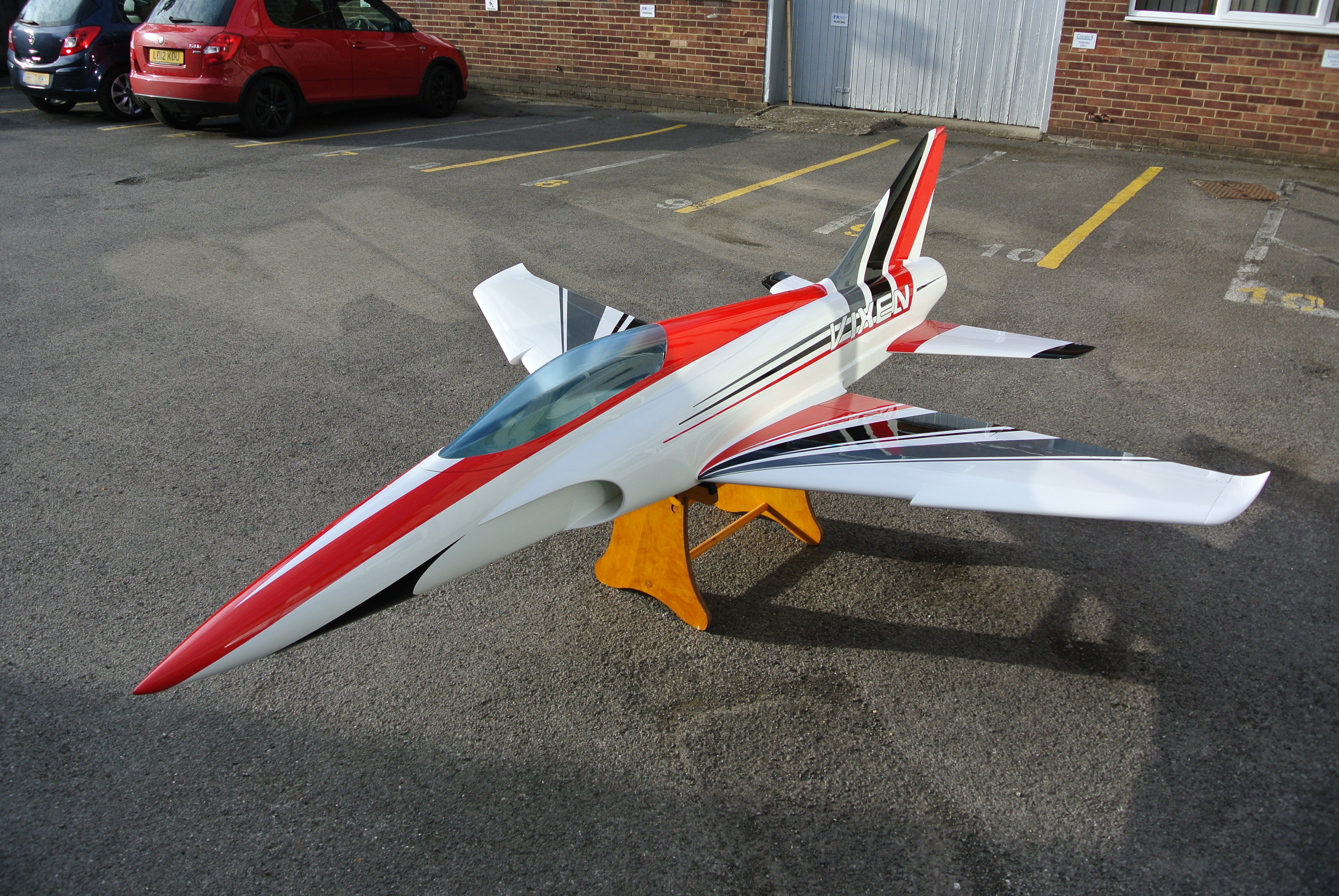
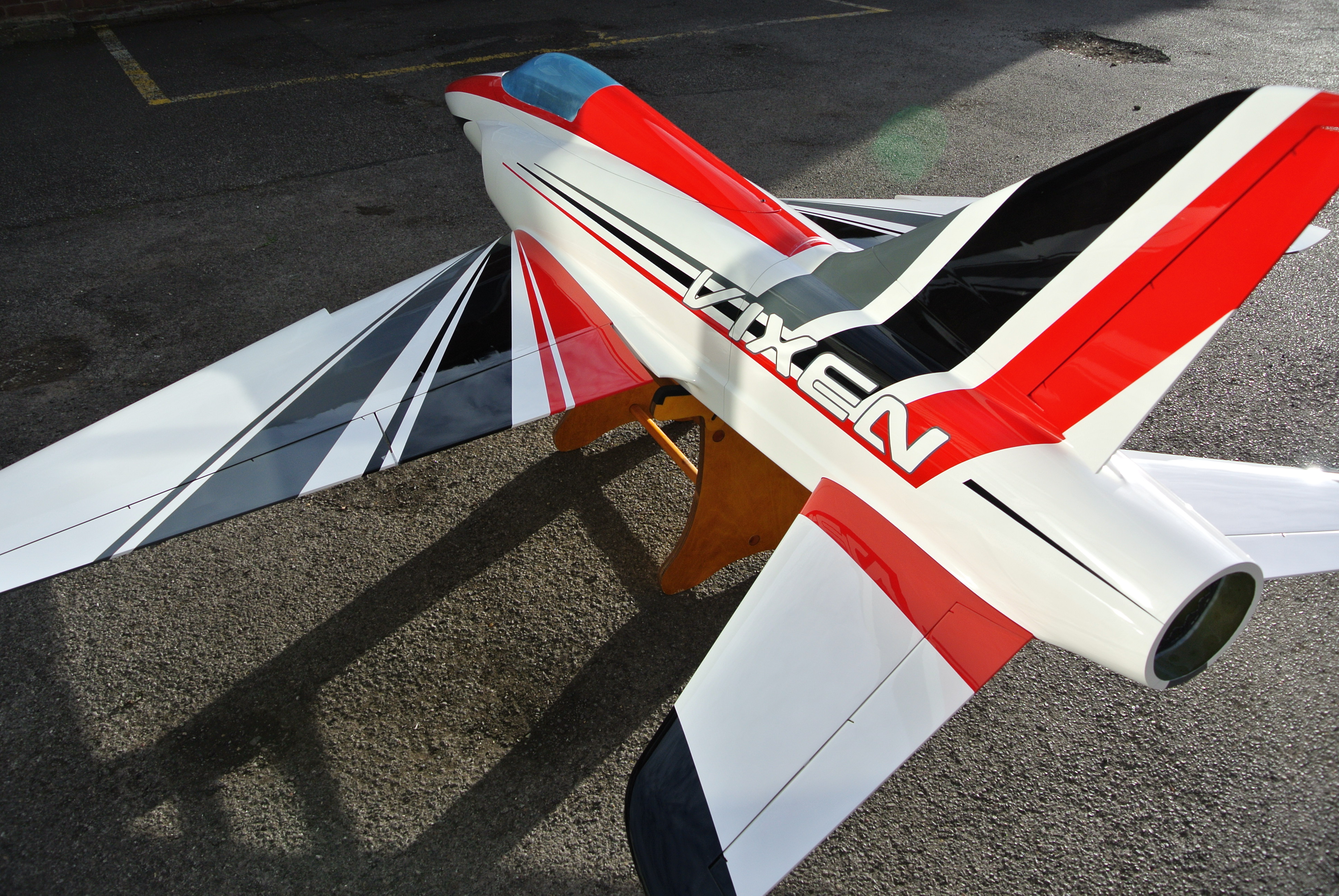
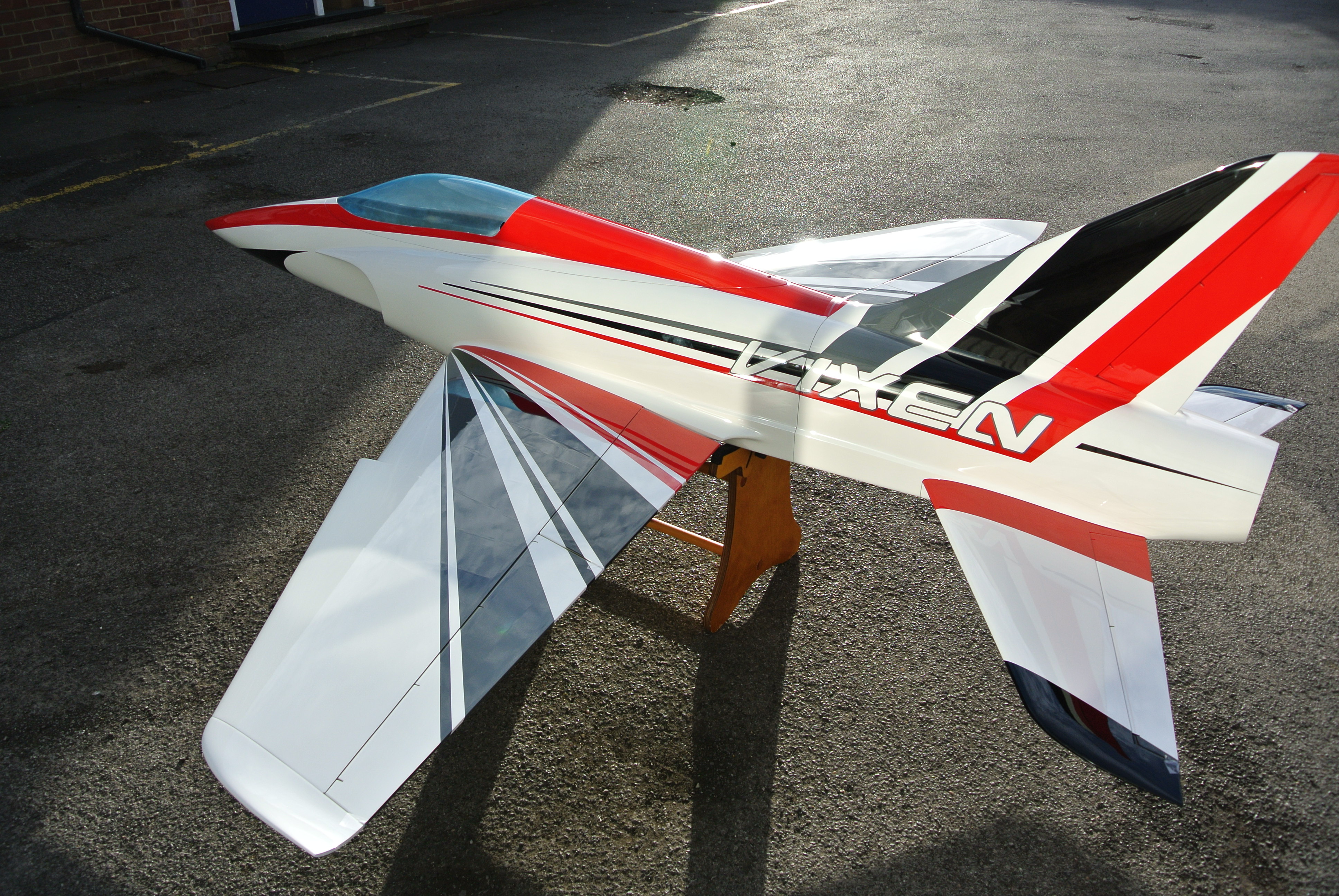
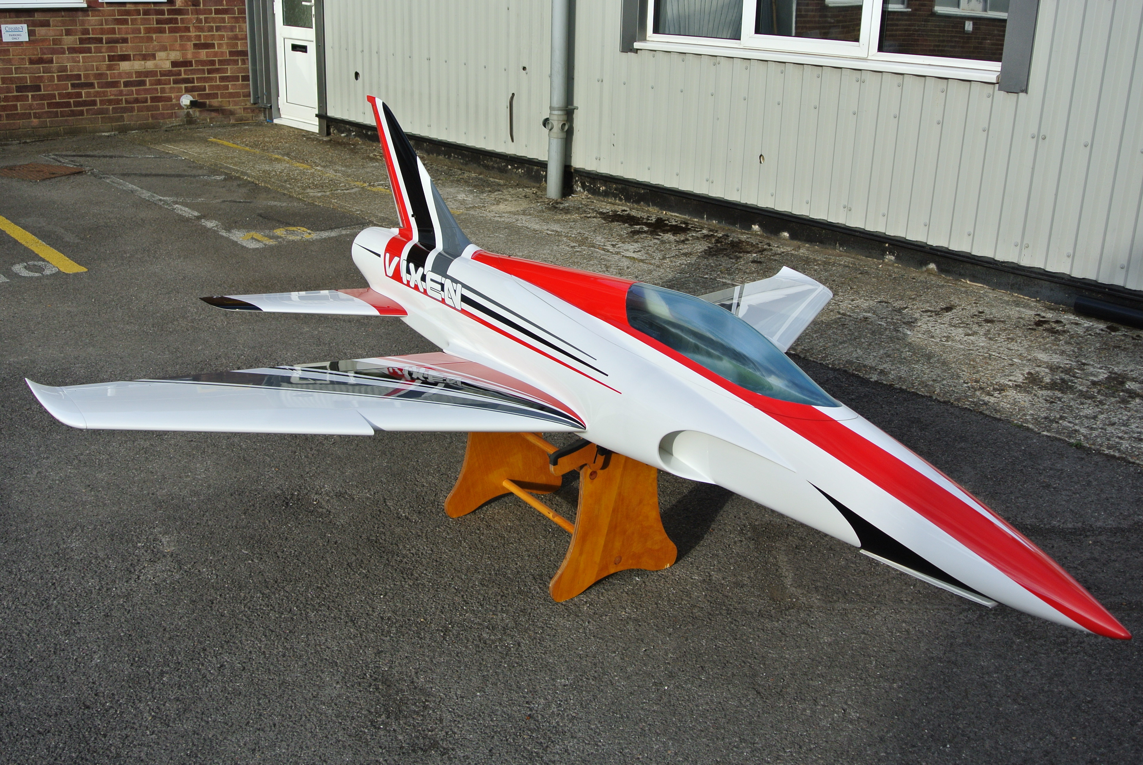
The VIXEN arrived earlier today, unpacked it after work hoping all was well.
The box looked as though it had been through the wars but luckily the main moulded parts were all in one piece with no damage, the canopy took a hit at some point and has been cracked and a piece missing at the rear on the side so hope to either repair, cover up or replace depending on time.
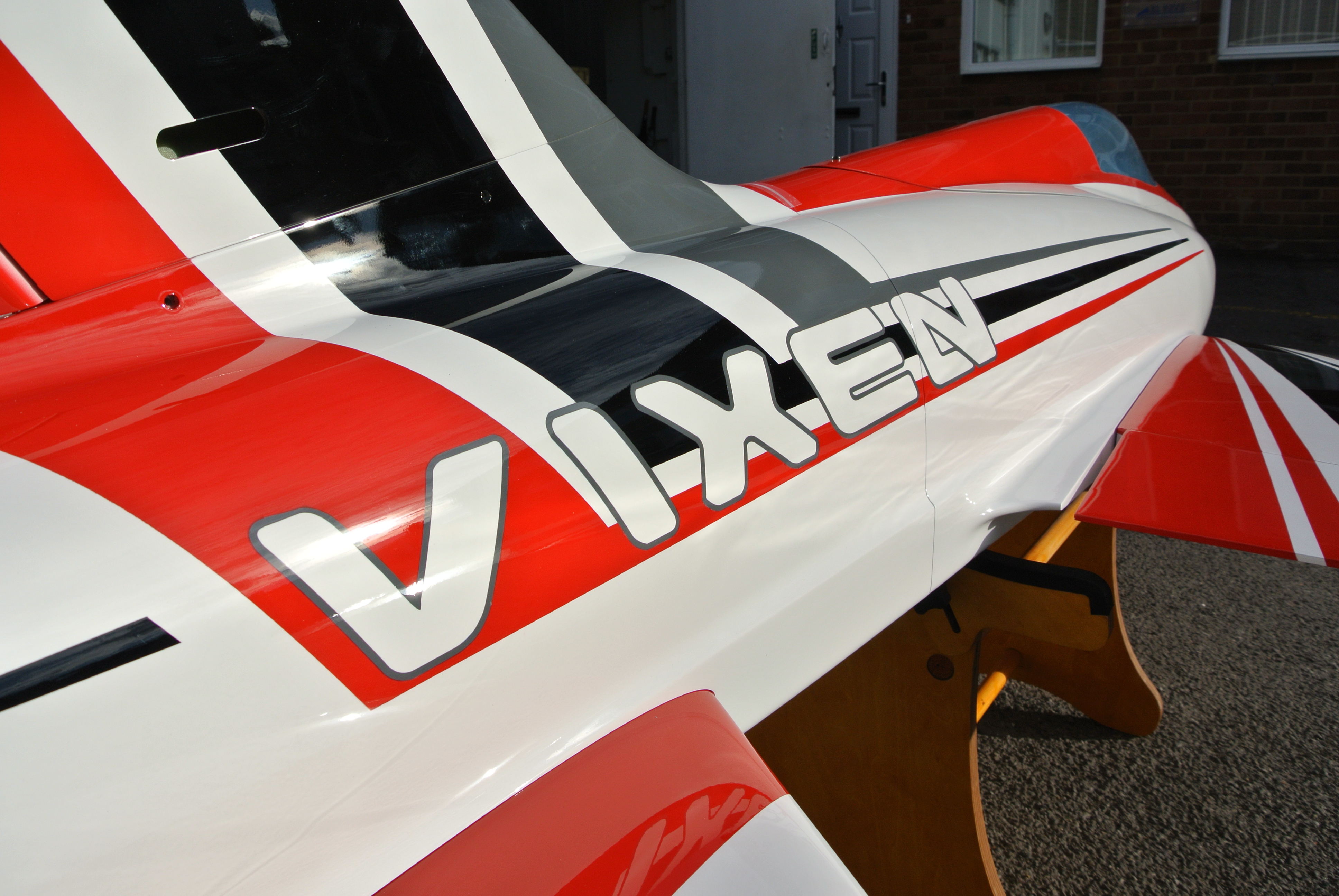
Paint is very good overall and nice not to have seams
Assembled the main parts and managed to get some shots in the sun tonight, looks like it wants to fly........
Will shoot some pics of the accessories although these might not be the final set as this is still the first 'production' model and my feedback will result in a few changes to hardware I am sure.
Bypass was included so will look to instal this and keep the propulsion system fully ducted, if time does not pan out will leave off for now.
More to follow over the next few days, enjoy.
marcs
The box looked as though it had been through the wars but luckily the main moulded parts were all in one piece with no damage, the canopy took a hit at some point and has been cracked and a piece missing at the rear on the side so hope to either repair, cover up or replace depending on time.
Paint is very good overall and nice not to have seams
Assembled the main parts and managed to get some shots in the sun tonight, looks like it wants to fly........
Will shoot some pics of the accessories although these might not be the final set as this is still the first 'production' model and my feedback will result in a few changes to hardware I am sure.
Bypass was included so will look to instal this and keep the propulsion system fully ducted, if time does not pan out will leave off for now.
More to follow over the next few days, enjoy.
marcs
07-23-2015, 07:52 AM
#13
Thread Starter
Join Date: Jan 2007
Location: farnborough, , UNITED KINGDOM
Posts: 3,294
Likes: 0
Received 1 Like
on
1 Post
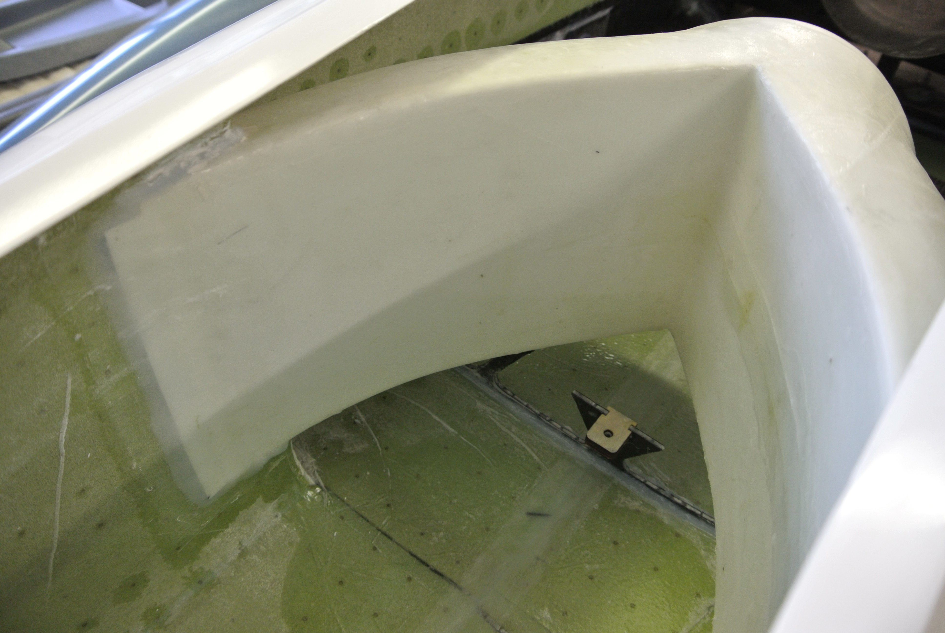
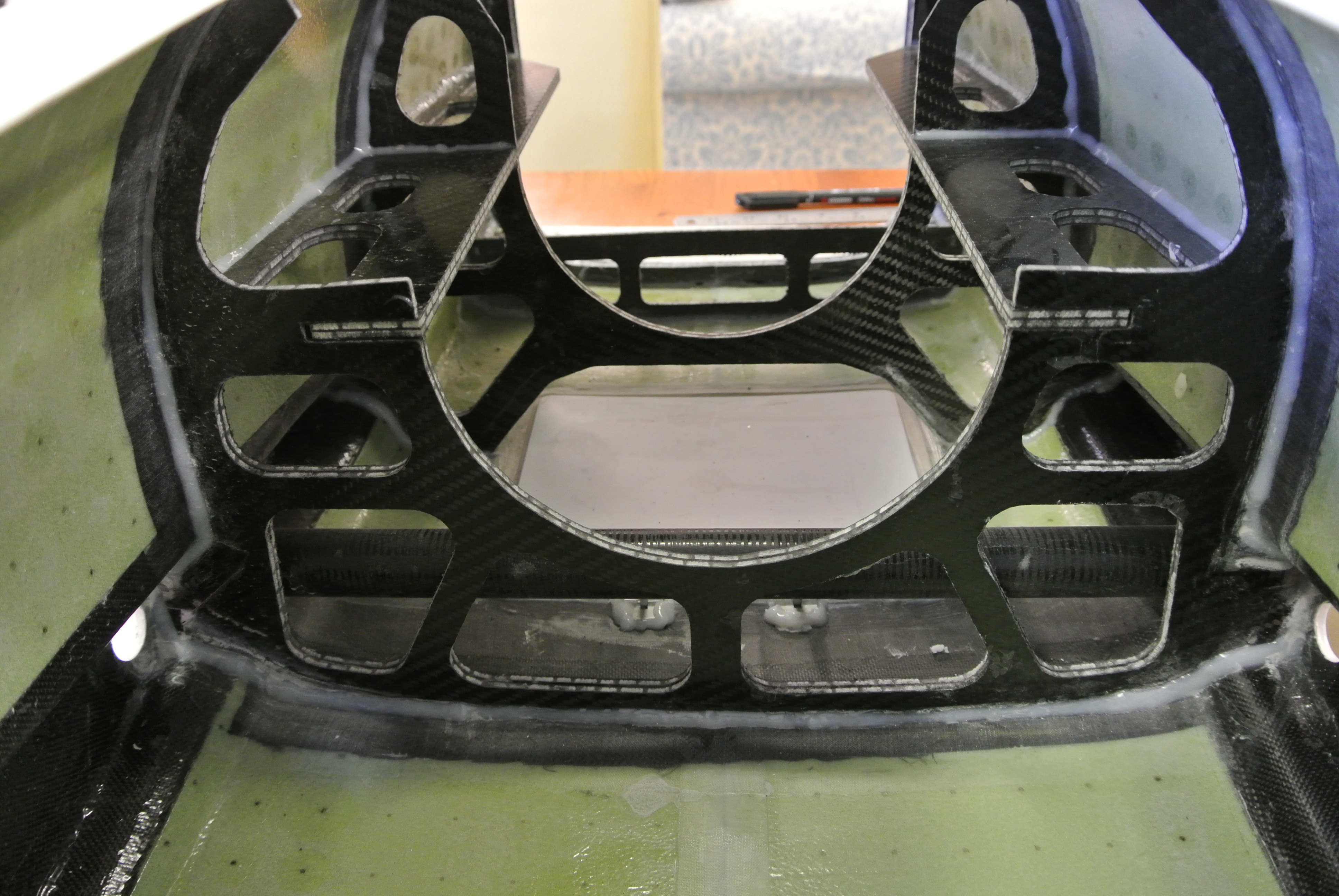
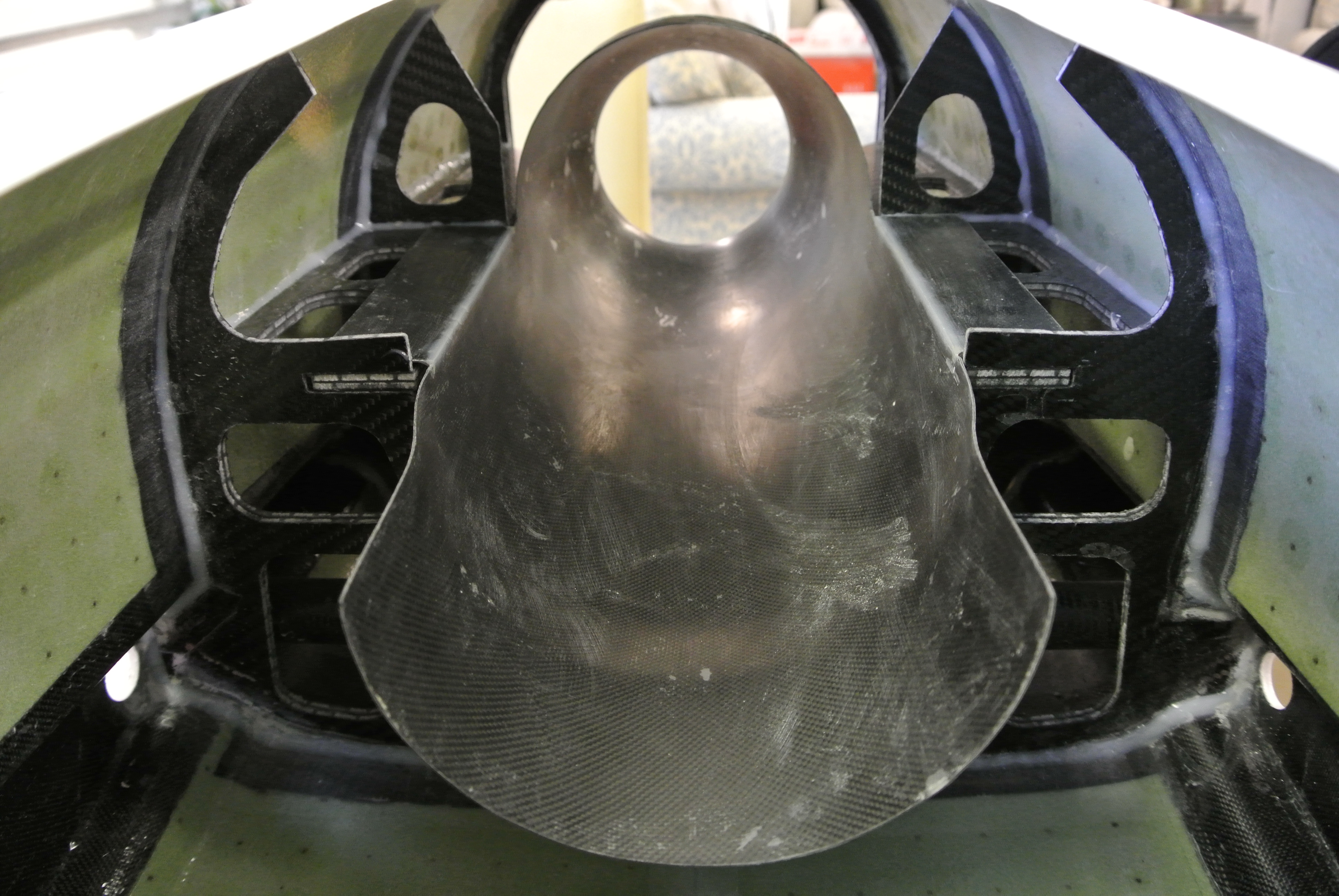
Nose wheel area:
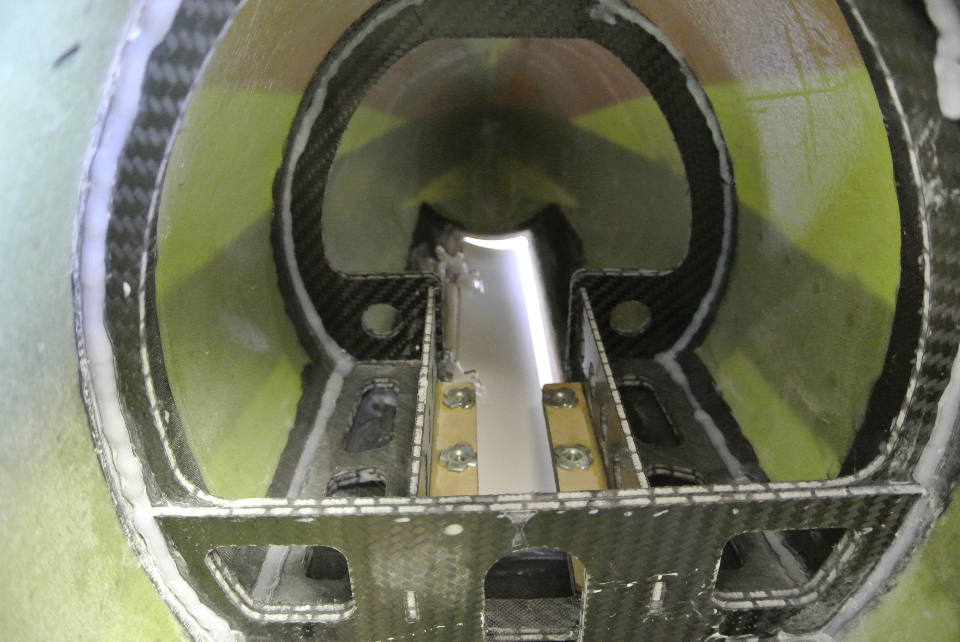
Equipment tray middle support:
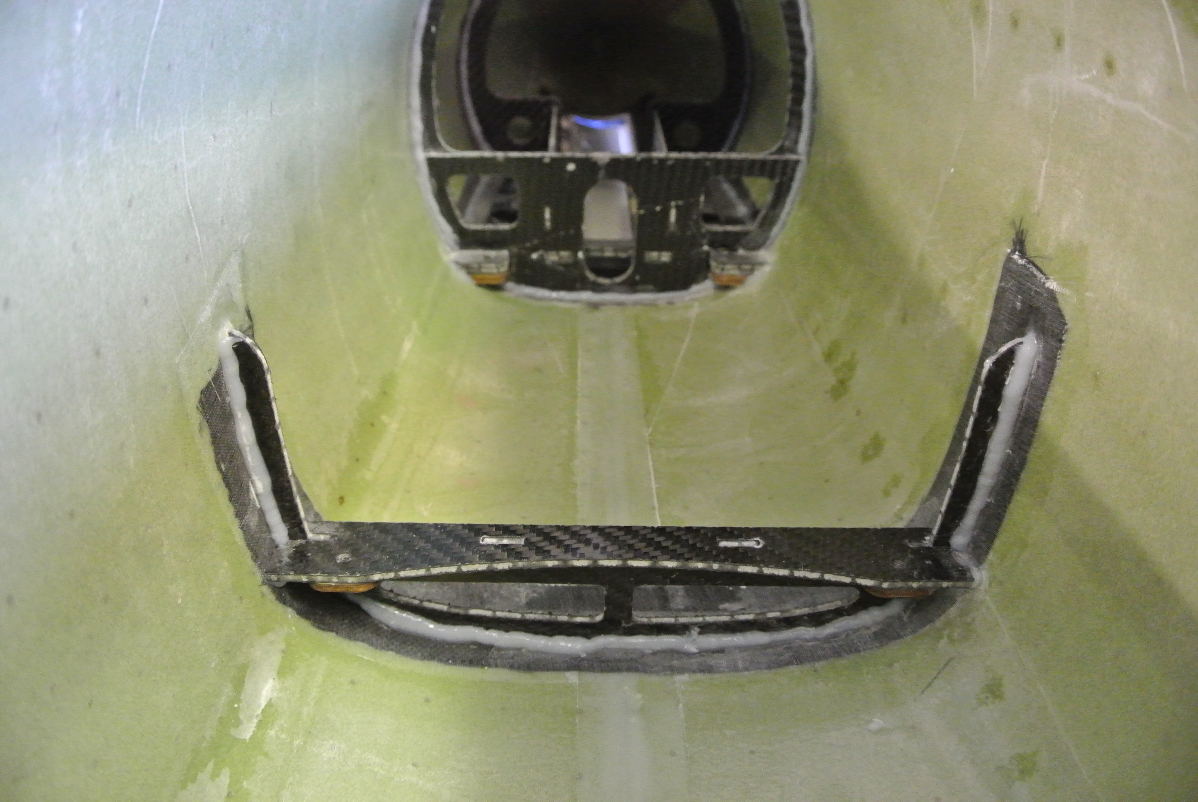
Duct blending:

Turbine former assembly (without and with lower bypass in place:
Rear main fuselage jointing section:
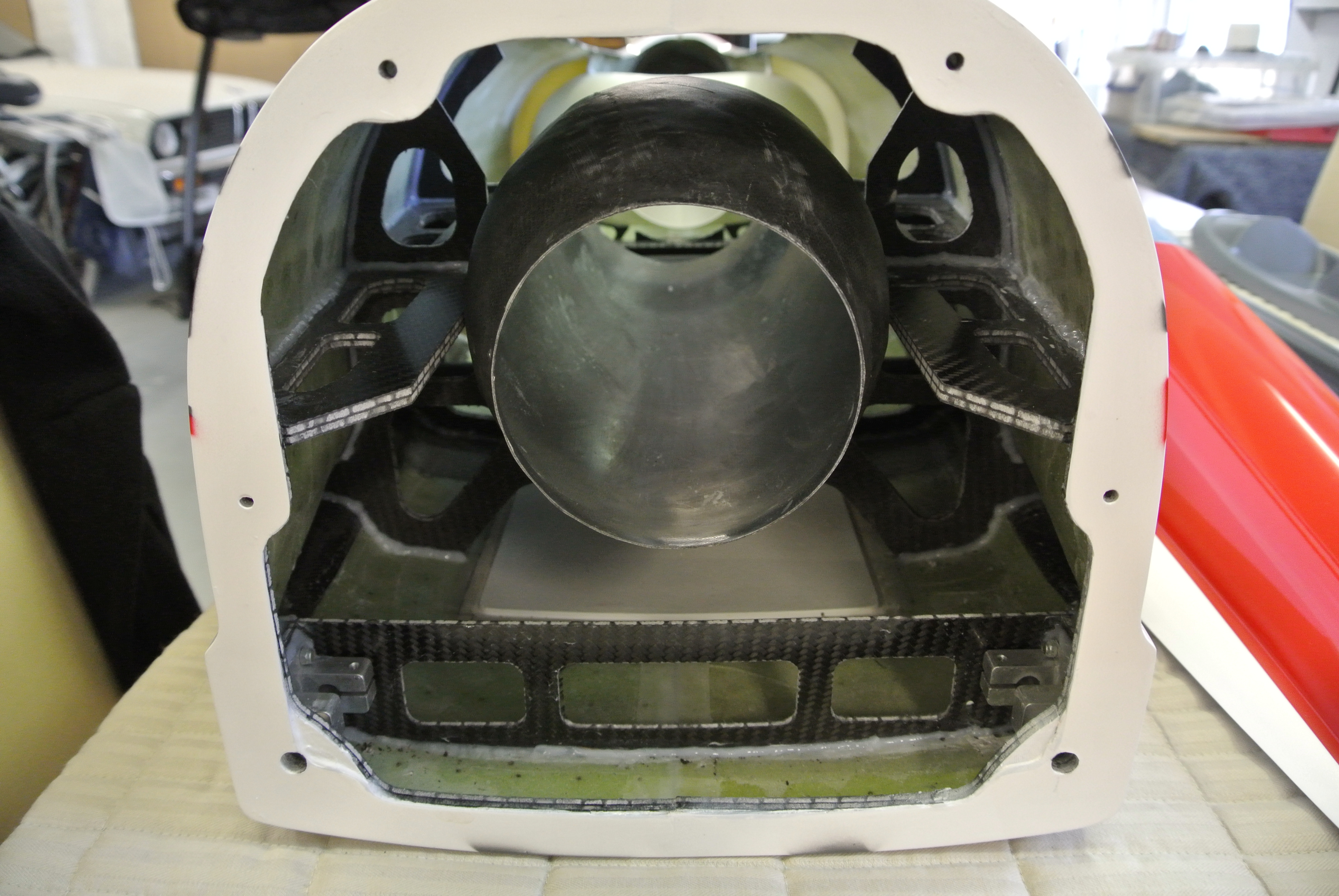
Rear section jointing face:
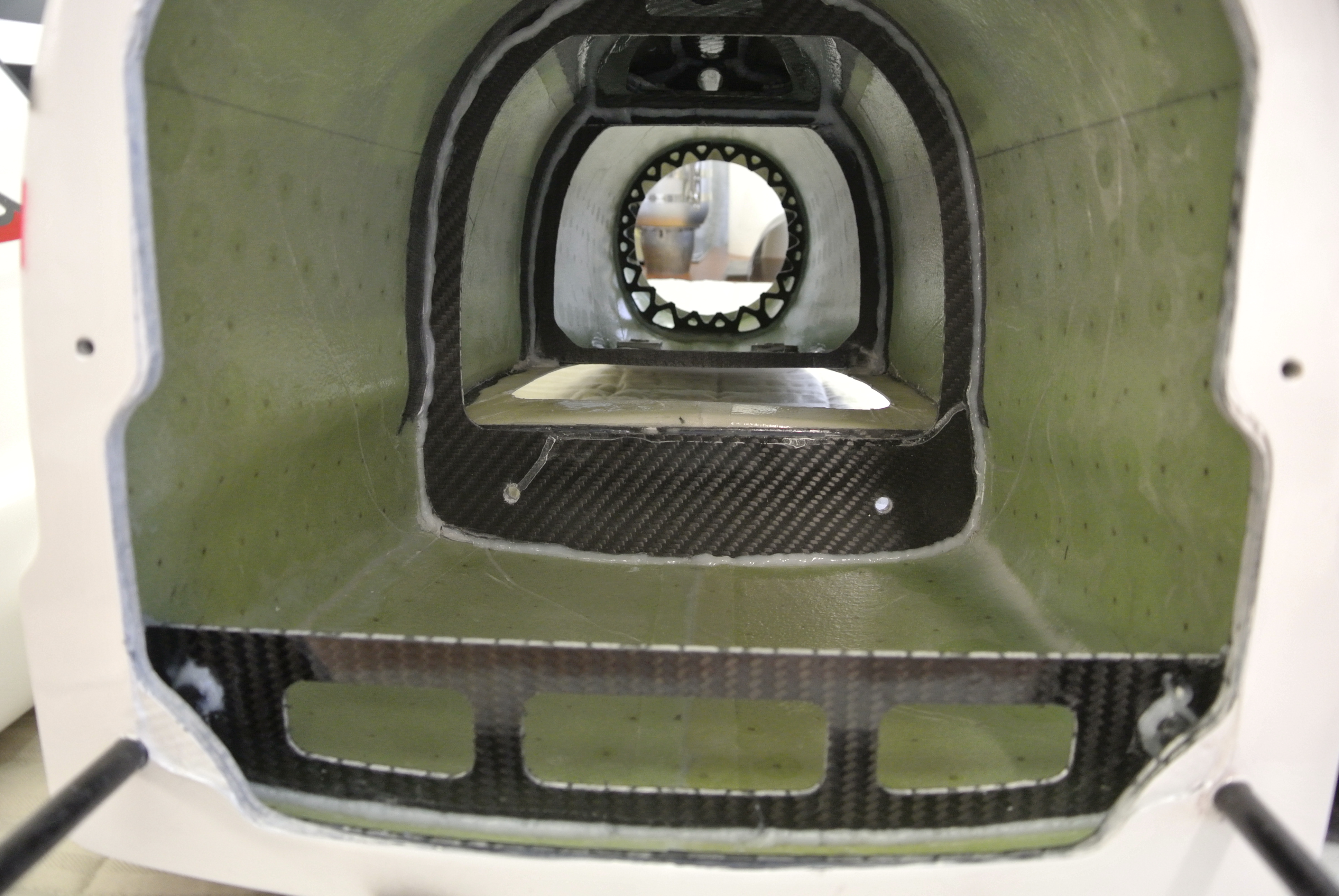
Rear pipe support and fin support formers:
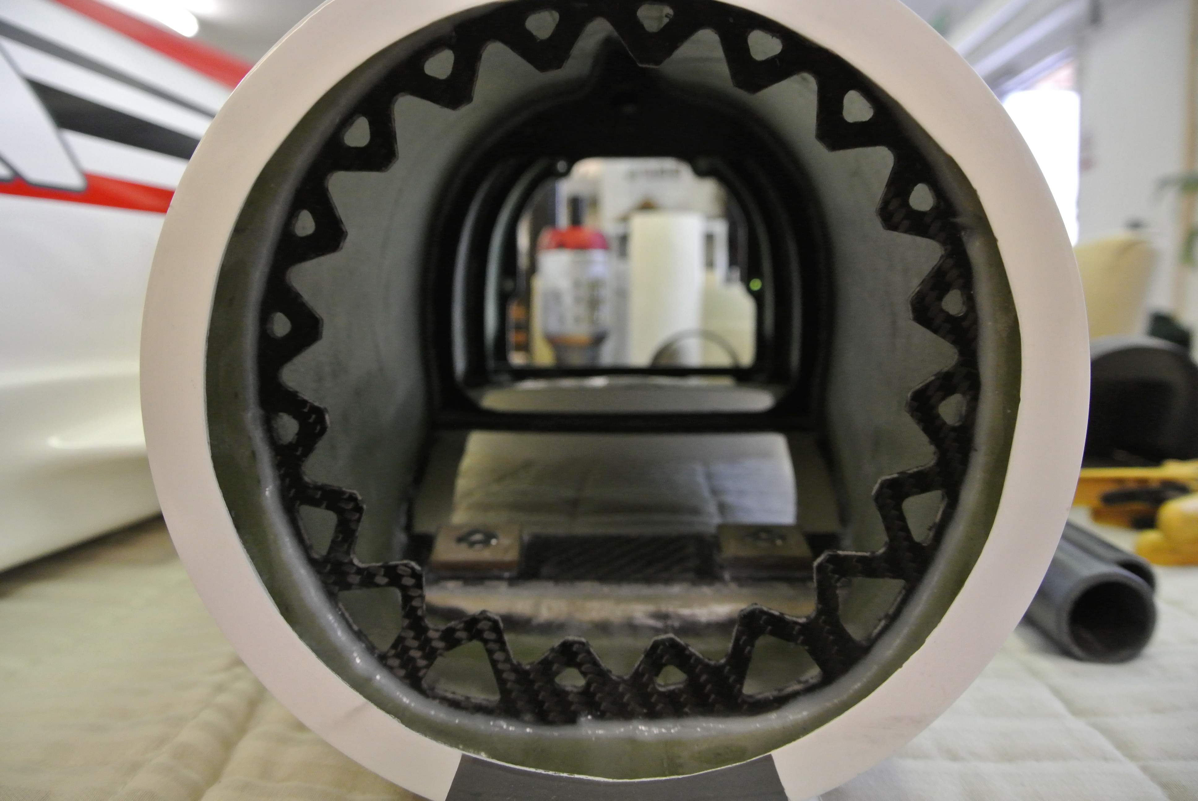
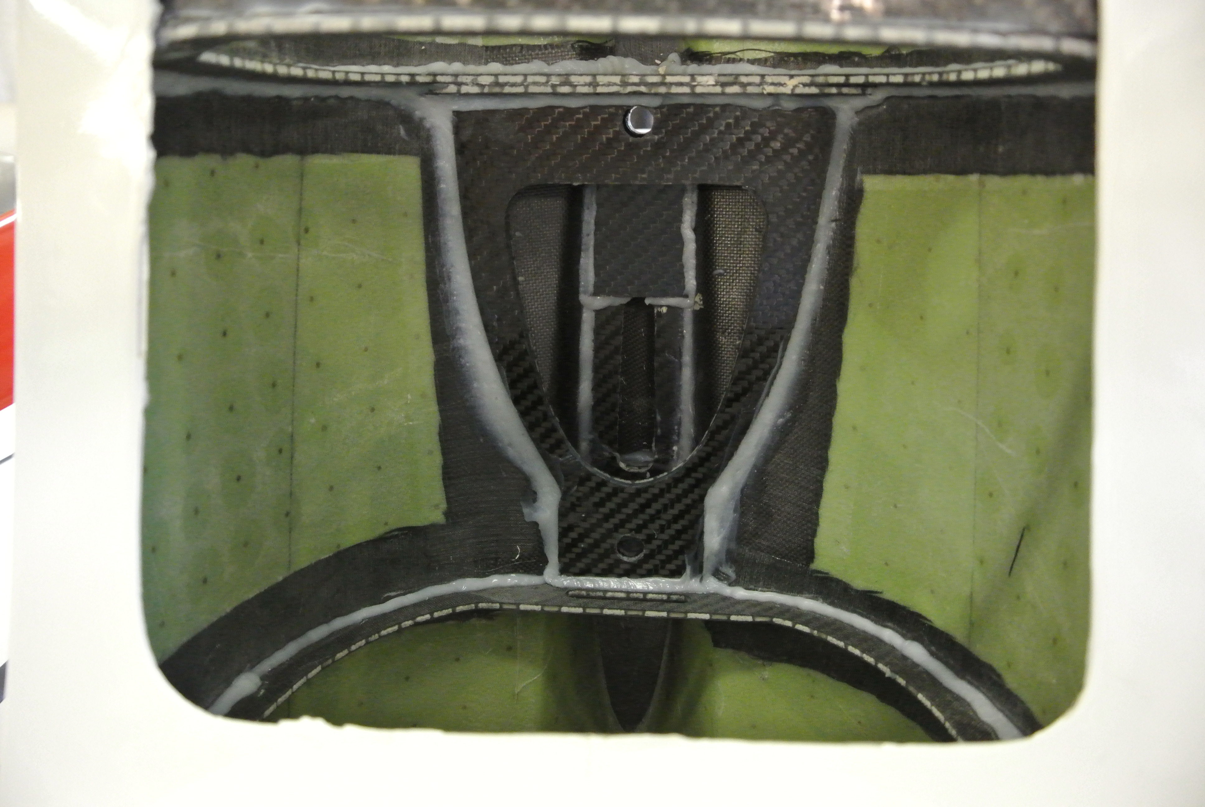
marcs
Equipment tray middle support:
Duct blending:
Turbine former assembly (without and with lower bypass in place:
Rear main fuselage jointing section:
Rear section jointing face:
Rear pipe support and fin support formers:
marcs
07-23-2015, 11:22 AM
#14


Join Date: Nov 2009
Location: AUSTINTOWN, OH
Posts: 564
Likes: 0
Received 0 Likes
on
0 Posts
I put my order in for one!!! Winter project for me.
Marc I love the Electron undercarriage. I had one made for the 2.5 viper and they works Great for my customers who have them!!
Thanks Billy D
Marc I love the Electron undercarriage. I had one made for the 2.5 viper and they works Great for my customers who have them!!
Thanks Billy D
07-24-2015, 12:38 AM
#15
Thread Starter
Join Date: Jan 2007
Location: farnborough, , UNITED KINGDOM
Posts: 3,294
Likes: 0
Received 1 Like
on
1 Post
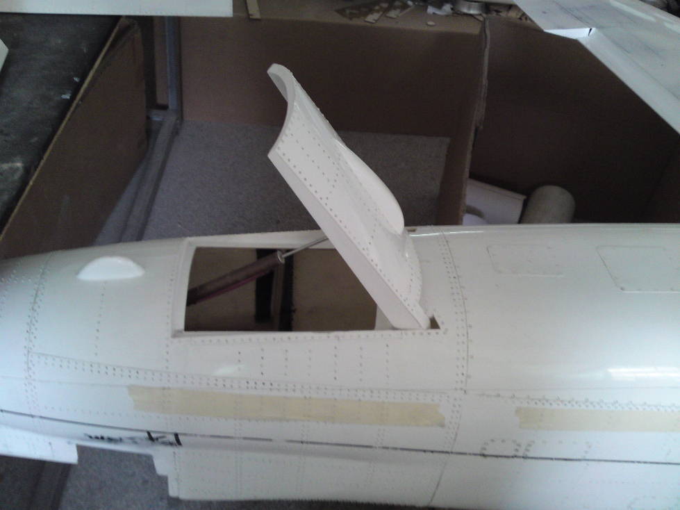
Fin
The rudder is pre hinged with a full length wire pin running through 3 pre-fitted lugs glued into the rudder, all moves freely without slop.
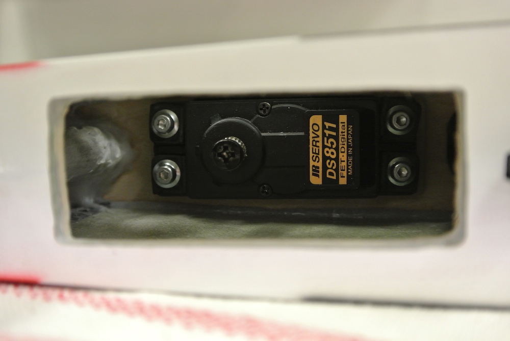
The servo location is inside the base of the fin rather than a hatch on the side, looks neater but slightly more fiddly to get the servo in. I'm using JR8511's on most surfaces and the pre-cut hole in the plate glued in the fin to accept the rudder servo was a perfect fit with no extra work needed, even the pilot holes for the servo screws lined up too.
I had to open out the opening in the base of the fin a little to get the 8511 in but this was a 10 minute job using my Permagrit files which if you have not heard of these tools do a Google search as they are invaluable to any model builder (big plug!).
I have not yet worked out the best servo arm lenght to get the desired throws (rudder 38mm from base line at rudder base) but have a 25mm and a 30mm arm on order to see which is best.
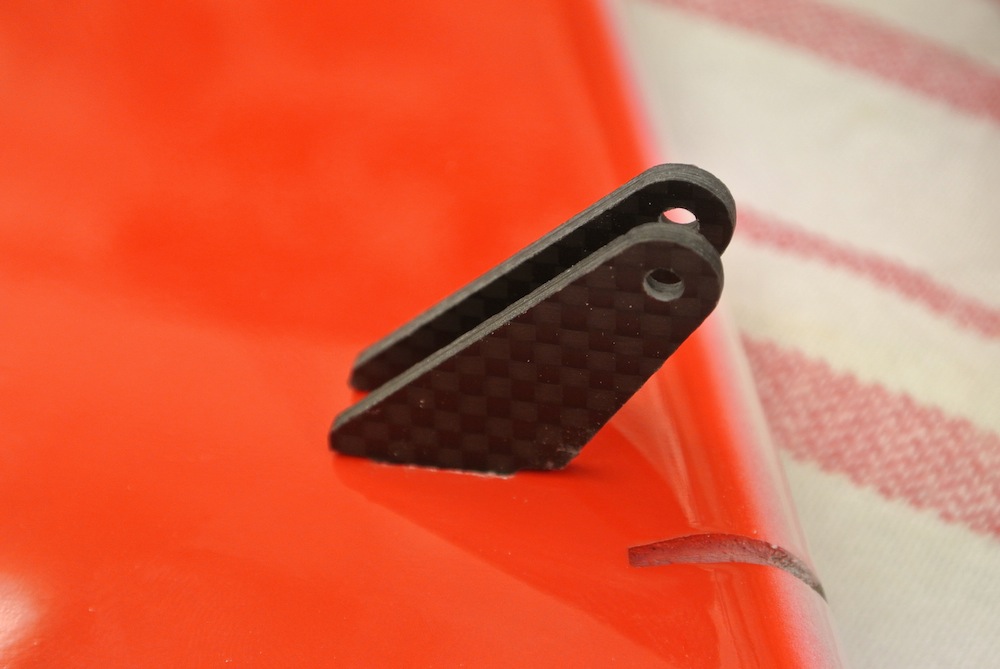
Rudder horns are supplied and are nicely made items cnc cut from 3mm carbon fibre plate, slots are pre made in the rudder so most of the work is done but they need opening out and preparing to accept the horns. Picture shows them in place but not glued, I will Hysol later today.
Rudder fixing to fuselage is via two aluminium rods (solid) which are well secured inside the fin and locate into the very strong formers fitted inside the rear section (picture in earlier post). Fin is secured to fuselage via two M3 bolts.
marcs
The rudder is pre hinged with a full length wire pin running through 3 pre-fitted lugs glued into the rudder, all moves freely without slop.
The servo location is inside the base of the fin rather than a hatch on the side, looks neater but slightly more fiddly to get the servo in. I'm using JR8511's on most surfaces and the pre-cut hole in the plate glued in the fin to accept the rudder servo was a perfect fit with no extra work needed, even the pilot holes for the servo screws lined up too.
I had to open out the opening in the base of the fin a little to get the 8511 in but this was a 10 minute job using my Permagrit files which if you have not heard of these tools do a Google search as they are invaluable to any model builder (big plug!).
I have not yet worked out the best servo arm lenght to get the desired throws (rudder 38mm from base line at rudder base) but have a 25mm and a 30mm arm on order to see which is best.
Rudder horns are supplied and are nicely made items cnc cut from 3mm carbon fibre plate, slots are pre made in the rudder so most of the work is done but they need opening out and preparing to accept the horns. Picture shows them in place but not glued, I will Hysol later today.
Rudder fixing to fuselage is via two aluminium rods (solid) which are well secured inside the fin and locate into the very strong formers fitted inside the rear section (picture in earlier post). Fin is secured to fuselage via two M3 bolts.
marcs
Last edited by marc s; 07-24-2015 at 12:55 AM.
07-24-2015, 02:28 AM
#17
Thread Starter
Join Date: Jan 2007
Location: farnborough, , UNITED KINGDOM
Posts: 3,294
Likes: 0
Received 1 Like
on
1 Post
Fin
Having adjusted holes and trimmed the tabs on the horns for a nice fit I keyed the horn tabs with an abrasive wheel and cleaned with acetone. I once had a messy experience with gluing horns so now I mask the slots so as not to make the same mistake again.
Blew out the slots to remove any dust etc and checked there was a hard block inside the rudder were the glue would fix properly to - there was phew!
Mixed up some 9462 with a spot of black pigment, filled the slots, fitted the horns - I repeat this a few times recharging the slots with epoxy to make sure its well covered and once happy pushed home the horns. I clean up the excess glue with cotton buds (Q-tips I think they are called in the US) remove the masking tape and leave to dry.
As the ball links I have on order for these horns have a 6mm wide fitting I added 6mm worth of washers to the horns using an M3 bolt to secure them so the spacing will be right when the linkage is attached, it also helps keep the horn holes in alignment.

marcs
Having adjusted holes and trimmed the tabs on the horns for a nice fit I keyed the horn tabs with an abrasive wheel and cleaned with acetone. I once had a messy experience with gluing horns so now I mask the slots so as not to make the same mistake again.
Blew out the slots to remove any dust etc and checked there was a hard block inside the rudder were the glue would fix properly to - there was phew!
Mixed up some 9462 with a spot of black pigment, filled the slots, fitted the horns - I repeat this a few times recharging the slots with epoxy to make sure its well covered and once happy pushed home the horns. I clean up the excess glue with cotton buds (Q-tips I think they are called in the US) remove the masking tape and leave to dry.
As the ball links I have on order for these horns have a 6mm wide fitting I added 6mm worth of washers to the horns using an M3 bolt to secure them so the spacing will be right when the linkage is attached, it also helps keep the horn holes in alignment.
marcs
07-27-2015, 06:12 AM
#18
Thread Starter
Join Date: Jan 2007
Location: farnborough, , UNITED KINGDOM
Posts: 3,294
Likes: 0
Received 1 Like
on
1 Post
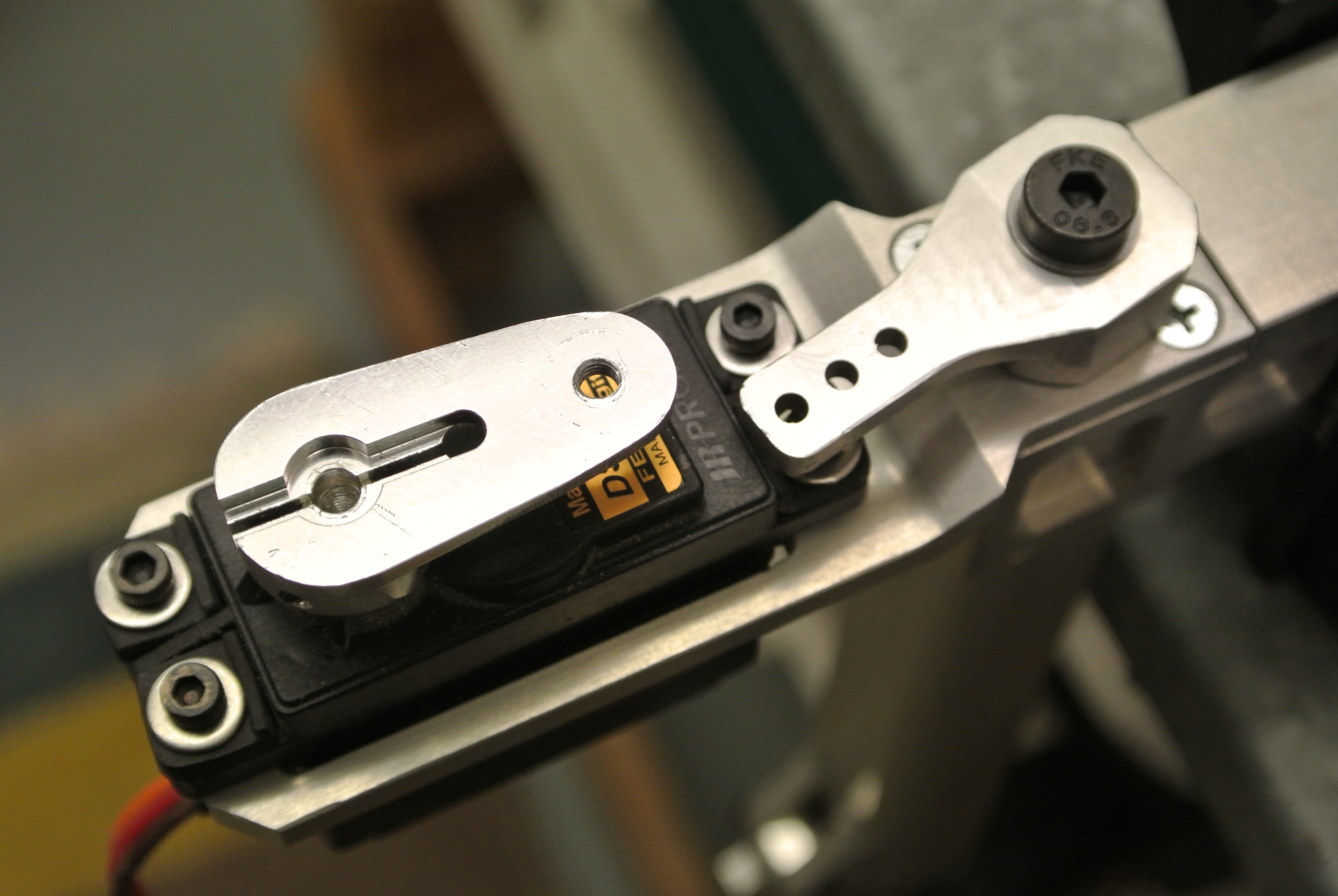
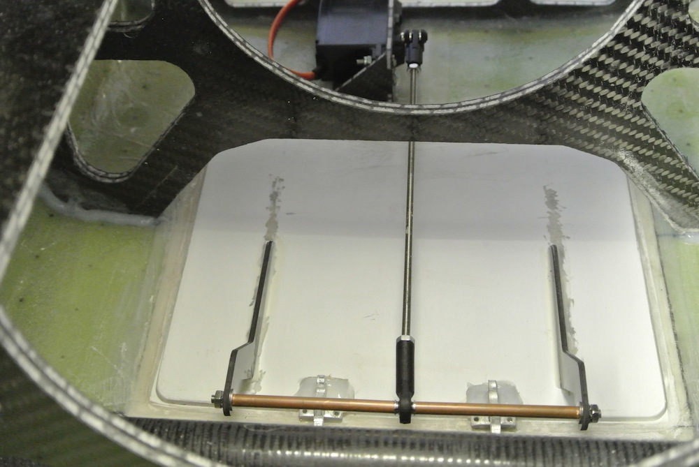
Speed Brake
The speed brake was an item I was keen to incorporate into this jet and Xtreme have included a well proportioned brake and supplied it pre-fitted with aluminium hinges.
I would have preferred to either have hinges not fitted or hinges that you could remove the pins from so that the brake could be removed to work on fitting the linkage. Hopefully the latter will be done on later kits.
When Rich built the first prototype he arranged the speed brake servo forward of the actual brake in front of the rear wing tube former, this location resulted in the servo location being off centre as the former has a central strengthening post, as a result and due to my weird desire to keep things symmetrical I have opted to locate the servo behind the brake so it can remain central. Hopefully it wont cause any issues operating the brake located here.
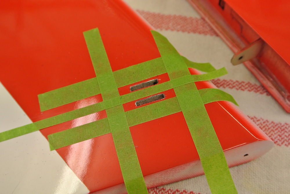
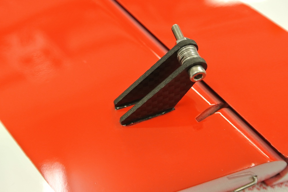
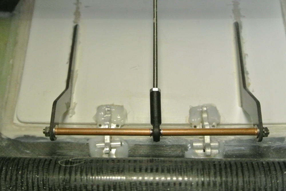
With hinges fitted all that is required to do is fit the horns, these are supplied as two cnc cut carbon fibre items which have long base legs to extend mid way down the brake to give a good area to fix the horns to. I guess you can fit them close together like a 'double' horn in between the hinges, I opted to spread them outboard of the hinges and make up a simple linkage bar from some 3mm threaded rod and copper tube slipped over at each end to locate the ball link at the mid-point.
Marked up the brake, keyed the area where the horn base legs were located positioning the linkage over the hinge point. Scuffed the horns, tacked them in place with cyano and microballons and then filleted with Hysol.
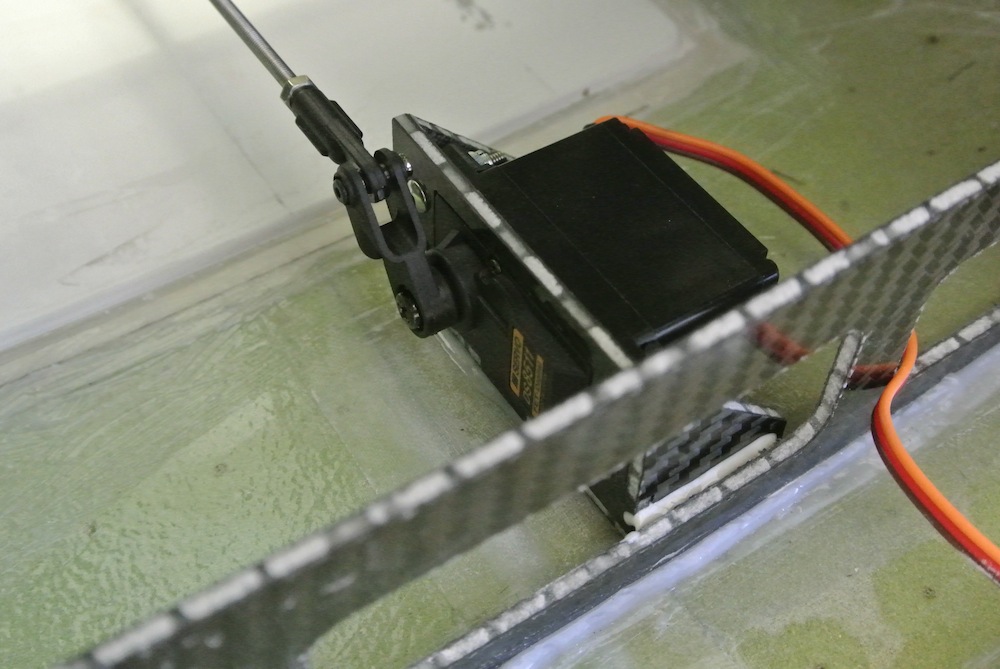
There is a servo tray supplied which comes in 4 parts, made from the same carbon sandwich material used in the formers of the Vixen, it assembles easily and after keying and cleaning with acetone I glued with cyan and microballons. The JR8511 fitted exactly without modification.
Sorted the threaded M3 rod linkage and ball link to give the right length and keyed the servo mount and fuselage base. Glued servo mount to fuselage with Hysol.
The speed brake was an item I was keen to incorporate into this jet and Xtreme have included a well proportioned brake and supplied it pre-fitted with aluminium hinges.
I would have preferred to either have hinges not fitted or hinges that you could remove the pins from so that the brake could be removed to work on fitting the linkage. Hopefully the latter will be done on later kits.
When Rich built the first prototype he arranged the speed brake servo forward of the actual brake in front of the rear wing tube former, this location resulted in the servo location being off centre as the former has a central strengthening post, as a result and due to my weird desire to keep things symmetrical I have opted to locate the servo behind the brake so it can remain central. Hopefully it wont cause any issues operating the brake located here.
With hinges fitted all that is required to do is fit the horns, these are supplied as two cnc cut carbon fibre items which have long base legs to extend mid way down the brake to give a good area to fix the horns to. I guess you can fit them close together like a 'double' horn in between the hinges, I opted to spread them outboard of the hinges and make up a simple linkage bar from some 3mm threaded rod and copper tube slipped over at each end to locate the ball link at the mid-point.
Marked up the brake, keyed the area where the horn base legs were located positioning the linkage over the hinge point. Scuffed the horns, tacked them in place with cyano and microballons and then filleted with Hysol.
There is a servo tray supplied which comes in 4 parts, made from the same carbon sandwich material used in the formers of the Vixen, it assembles easily and after keying and cleaning with acetone I glued with cyan and microballons. The JR8511 fitted exactly without modification.
Sorted the threaded M3 rod linkage and ball link to give the right length and keyed the servo mount and fuselage base. Glued servo mount to fuselage with Hysol.
07-27-2015, 07:22 AM
#19
My Feedback: (1)
Join Date: Jul 2002
Location: SevenoaksKent, UNITED KINGDOM
Posts: 5,193
Likes: 0
Received 0 Likes
on
0 Posts
Marc,
Another option to open the speed brake from that servo position is to do it the same way as on a Hawk. Would be a simpler setup as there'd be no need for the extra horns and linkage bar - just a lug toward the mid/rear of the speedbrake to connect to. Would also offer more mechanical advantage?
M
Another option to open the speed brake from that servo position is to do it the same way as on a Hawk. Would be a simpler setup as there'd be no need for the extra horns and linkage bar - just a lug toward the mid/rear of the speedbrake to connect to. Would also offer more mechanical advantage?
M
07-27-2015, 07:55 AM
#20
Thread Starter
Join Date: Jan 2007
Location: farnborough, , UNITED KINGDOM
Posts: 3,294
Likes: 0
Received 1 Like
on
1 Post
Mark, possible solution too, might need to raise the servo mount up to get the angle which would involve some mods to the servo frame but possible - appreciate the suggestion.
marcs
marcs
 07-27-2015, 08:54 AM
#22
Thread Starter
Join Date: Jan 2007
Location: farnborough, , UNITED KINGDOM
Posts: 3,294
Likes: 0
Received 1 Like
on
1 Post
Dave it's a stainless M3 threaded rod with a copper sleeve over it each side of the ball link, I'm pretty sure it will be fine but as an alternative I have a length of 3mm solid carbon rod which might serve better - will check the flex once the servo mount has cured.
If it proves not to be stiff enough I will upgrade to a 4mm carbon rod or tube.
marcs
If it proves not to be stiff enough I will upgrade to a 4mm carbon rod or tube.
marcs
07-27-2015, 09:13 AM
#23
As has been pointed out the large span between horns might not be ideal, but can be overcome using the methods you described.
The other observation I have is with the servo behind the air brake it appears that you can not use the mechanical advantage of the servo arm position, (i.e. directly away and in line with the linkage) when the air brake is fully deployed with the servo arm that is shown.
The other observation I have is with the servo behind the air brake it appears that you can not use the mechanical advantage of the servo arm position, (i.e. directly away and in line with the linkage) when the air brake is fully deployed with the servo arm that is shown.
07-27-2015, 09:33 AM
#24
As has been pointed out the large span between horns might not be ideal, but can be overcome using the methods you described.
The other observation I have is with the servo behind the air brake it appears that you can not use the mechanical advantage of the servo arm position, (i.e. directly away and in line with the linkage) when the air brake is fully deployed with the servo arm that is shown.
The other observation I have is with the servo behind the air brake it appears that you can not use the mechanical advantage of the servo arm position, (i.e. directly away and in line with the linkage) when the air brake is fully deployed with the servo arm that is shown.
Ultimately I prefer an air ram, servos are loaded always and if they get a stuck gear you can't land with the airbrake open to slow it (without perfect timing on a switch) as the servo will be destroyed, an air ram can compress.
With the 8511 holding power and expected slow flight from big flaps, it won't be loaded too much/too long.
07-27-2015, 02:35 PM
#25
Dave I agree, pulling is always better than pushing when it comes to longer
control rods. However, In my set up it was short and was a non-issue

You do need a very hi torque servo for this set up though.
As far as needing the airbrake, the first couple of flights were flown without using it, the flaps are very effective, the air brake is a bonus!
Last edited by RCISFUN; 07-27-2015 at 02:38 PM.