


VIXEN - virtual build thread
 07-28-2015, 06:13 AM
#26

I am intrigued by the nose wheel steering. How do you connect the servo arm to the gear arm? Or is the photo deceptive and the arms are actually perpendicular to the mechanism?
 07-28-2015, 08:44 AM
#27

Thread Starter
Join Date: Jan 2007
Location: farnborough, , UNITED KINGDOM
Posts: 3,294
Likes: 0
Received 1 Like
on
1 Post
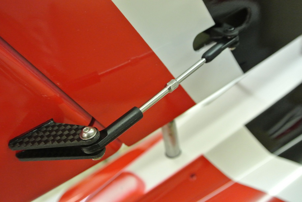
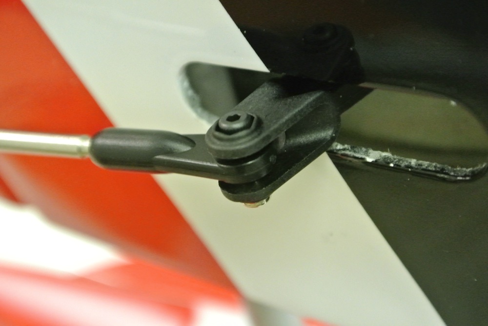
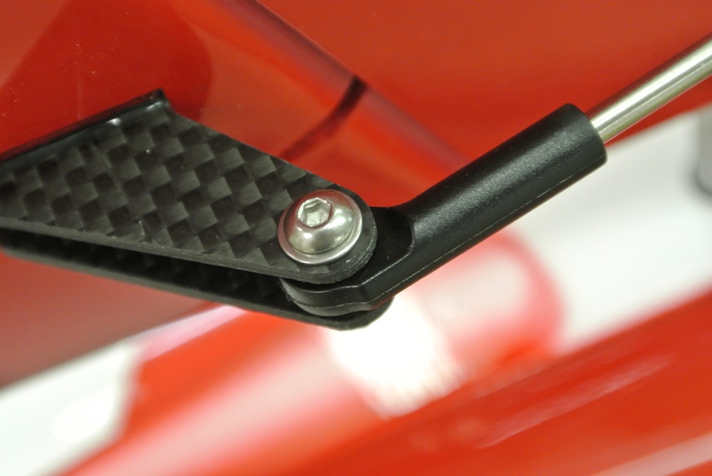
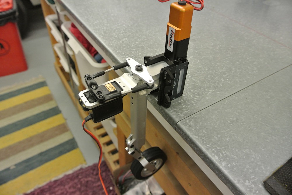
The nose wheel has a tiller at the top with a servo type arm, this connects to the servo arm via a connecting rod with ball links.
I'm changing this and machining up a tiller with dual arms, this means the connecting rods form a pull-pull link rather than a single push-pull, will post more pics when done.
marcs
I'm changing this and machining up a tiller with dual arms, this means the connecting rods form a pull-pull link rather than a single push-pull, will post more pics when done.
marcs
07-29-2015, 08:07 AM
#28
The photo shows the tiller pointing straight at the servo arm. This would require some sort of stretching connecting rod. Since the servo is mounted to the strut I didn't know if there wa a clearance problem with having the arm to the side. I'm assuming the photo is wrong and normally the arms do point to the side especially since you say you are using a dual-arm tiller.
I use a pull-pull connection from my rudder on my Stampe to the tail-wheel with the "connecting rods" being springs.
I use a pull-pull connection from my rudder on my Stampe to the tail-wheel with the "connecting rods" being springs.
Last edited by rgburrill; 07-29-2015 at 08:11 AM.
07-29-2015, 02:11 PM
#29
Thread Starter
Join Date: Jan 2007
Location: farnborough, , UNITED KINGDOM
Posts: 3,294
Likes: 0
Received 1 Like
on
1 Post
Yes the shot is not showing the tiller in the correct position, just how it was when the shot was taken, I will post an assembled unit with the double arm tiller when ready.
Fin
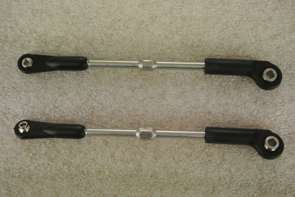
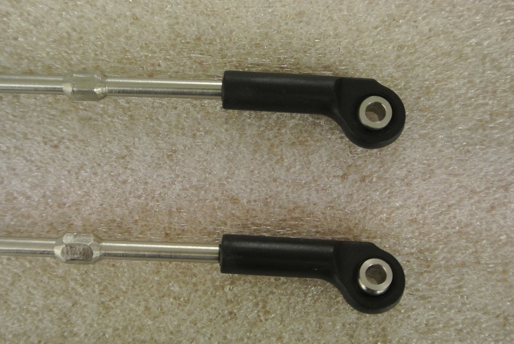
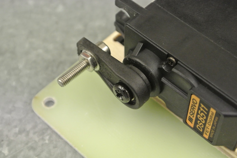
After gluing in the horns the connection rod was assembled from the turnbuckle supplied with the kit which is a perfect length, the horn at the servo arm end which comes with the U servo horn and an offset ball link at the control horn end.
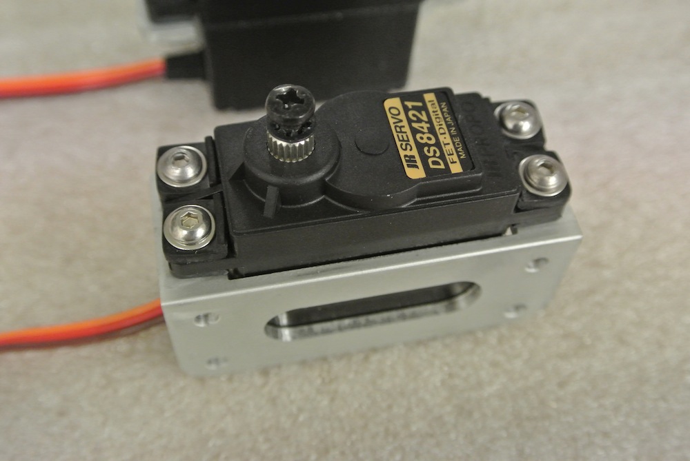
The servos used so far are JR8511's on ailerons, rudder and flaps. The elevators are JR8421 as the depth to work with does not allow an 8511 so the 2mm difference helps to get the slimmer unit into the stab.
Stab
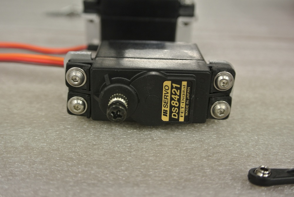
Mounted the 8421's into the supplied aluminium frames which are strong and well made and supplied in the kit, the space is tight even with the 8421's so you will notice I have filed the end on the aluminium mount so it is flush with the servo lug to help squeeze the unit into the space. After some more trail and error there was a light pressure being applied on the top stab skin when the servo plate was screwed down so had two choices
1- Remove some airex material from inside the top skin
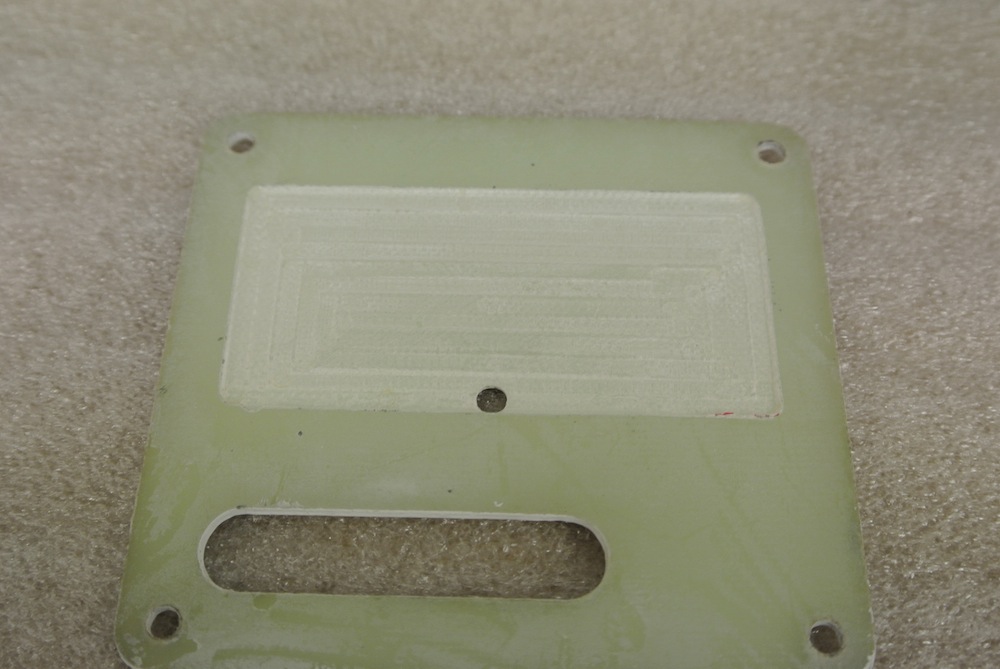
2- Mill some material off the servo cover (this is 1.6mm thick FR4)
I opted to do the latter and milled 1mm off the area where the aluminium servo frame would sit on the servo cover, now all fits nice without pressure on the wing skin.
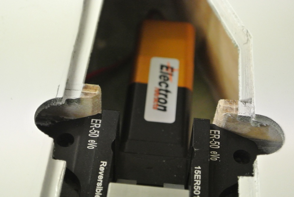
Landing Gear
Started to mod the gear mounts to accept the Electron ER50's as I wanted to keep the Vixen all electric, the gear it comes with is very good, its just my choice.
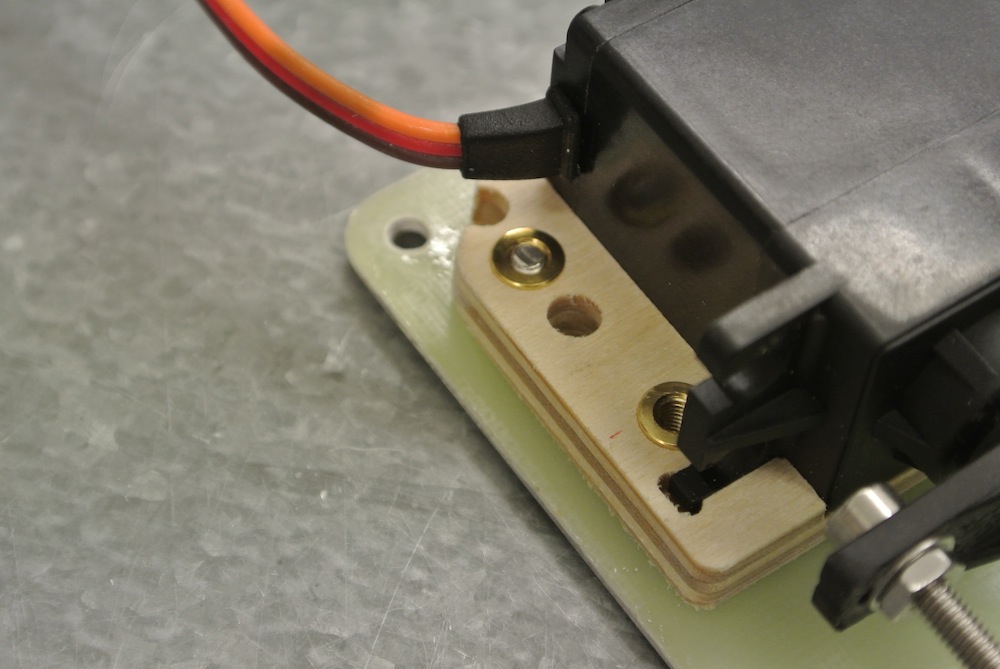
The nose gear needed the rails opening up as the ER50 is wider than the standard gear, as the rails fitted already have the bolt retaining nuts fitted I first had to remove them to make the trimming possible, a little work with a long M4 bolt and a screw driver got them out (they are well fixed in). I used a carbide rotary sander on a Proxxon drill and sanded the edges down to the correct width having put masking tape where I need to get to as a guide.
Once the rails were the correct width I had to adjust the mounting height as again the units differ, this was achieved by inserting two beech rails between the ER50 and the existing rails, the end result looks about right but will need checking with the nose wheel fitted.
More on this later....
marcs
Fin
After gluing in the horns the connection rod was assembled from the turnbuckle supplied with the kit which is a perfect length, the horn at the servo arm end which comes with the U servo horn and an offset ball link at the control horn end.
The servos used so far are JR8511's on ailerons, rudder and flaps. The elevators are JR8421 as the depth to work with does not allow an 8511 so the 2mm difference helps to get the slimmer unit into the stab.
Stab
Mounted the 8421's into the supplied aluminium frames which are strong and well made and supplied in the kit, the space is tight even with the 8421's so you will notice I have filed the end on the aluminium mount so it is flush with the servo lug to help squeeze the unit into the space. After some more trail and error there was a light pressure being applied on the top stab skin when the servo plate was screwed down so had two choices
1- Remove some airex material from inside the top skin
2- Mill some material off the servo cover (this is 1.6mm thick FR4)
I opted to do the latter and milled 1mm off the area where the aluminium servo frame would sit on the servo cover, now all fits nice without pressure on the wing skin.
Landing Gear
Started to mod the gear mounts to accept the Electron ER50's as I wanted to keep the Vixen all electric, the gear it comes with is very good, its just my choice.
The nose gear needed the rails opening up as the ER50 is wider than the standard gear, as the rails fitted already have the bolt retaining nuts fitted I first had to remove them to make the trimming possible, a little work with a long M4 bolt and a screw driver got them out (they are well fixed in). I used a carbide rotary sander on a Proxxon drill and sanded the edges down to the correct width having put masking tape where I need to get to as a guide.
Once the rails were the correct width I had to adjust the mounting height as again the units differ, this was achieved by inserting two beech rails between the ER50 and the existing rails, the end result looks about right but will need checking with the nose wheel fitted.
More on this later....
marcs
Last edited by marc s; 07-29-2015 at 02:17 PM.
07-29-2015, 11:55 PM
#30

My Feedback: (33)
Join Date: Feb 2002
Location: Chicago, IL
Posts: 469
Likes: 0
Received 0 Likes
on
0 Posts
Hi Marc,
Who makes the doubled servo arm, as well as the offset ball link? What material is the double arm made?
Appreciate your efforts here on the build. I'm looking forward to my Vixen and this will be quite valuable info.
Regards,
Keith
Who makes the doubled servo arm, as well as the offset ball link? What material is the double arm made?
Appreciate your efforts here on the build.
I'm looking forward to my Vixen and this will be quite valuable info.Regards,
Keith
07-30-2015, 12:46 AM
#31
Thread Starter
Join Date: Jan 2007
Location: farnborough, , UNITED KINGDOM
Posts: 3,294
Likes: 0
Received 1 Like
on
1 Post
Keith welcome.
The servo arms are made by a company in Germany called Gabriel Stahlformenbau, I buy mine from http://www.der-schweighofer.at/en/pr...m3_kugelgelenk simply because their web site has an English menu option which makes navigation a little easier. They are superb items and very well made from a high temp carbon/plastic process.
The servo arms are made by a company in Germany called Gabriel Stahlformenbau, I buy mine from http://www.der-schweighofer.at/en/pr...m3_kugelgelenk simply because their web site has an English menu option which makes navigation a little easier. They are superb items and very well made from a high temp carbon/plastic process.
The part number for the servo horns used on the aileron, stabs and rudder is 992811JR it's a 25mm length arm. I used the 72mm overall length turnbuckles supplied in the kit accessories pack.
I bought the offset ball links a long while ago, seem to remember getting them from an RC buggy shop but sorry do not have the details on these but a normal M3 good quality item should be fine.
I'm just playing with the flap linkage and servo set up now so will post the final details on what is used once this is done.
Hope that helps.
marcs
Last edited by marc s; 07-30-2015 at 12:49 AM.
07-30-2015, 10:37 AM
#32
Thread Starter
Join Date: Jan 2007
Location: farnborough, , UNITED KINGDOM
Posts: 3,294
Likes: 0
Received 1 Like
on
1 Post
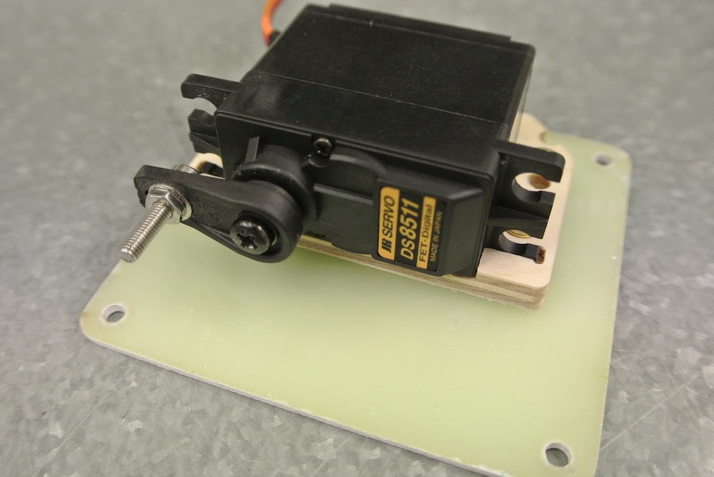
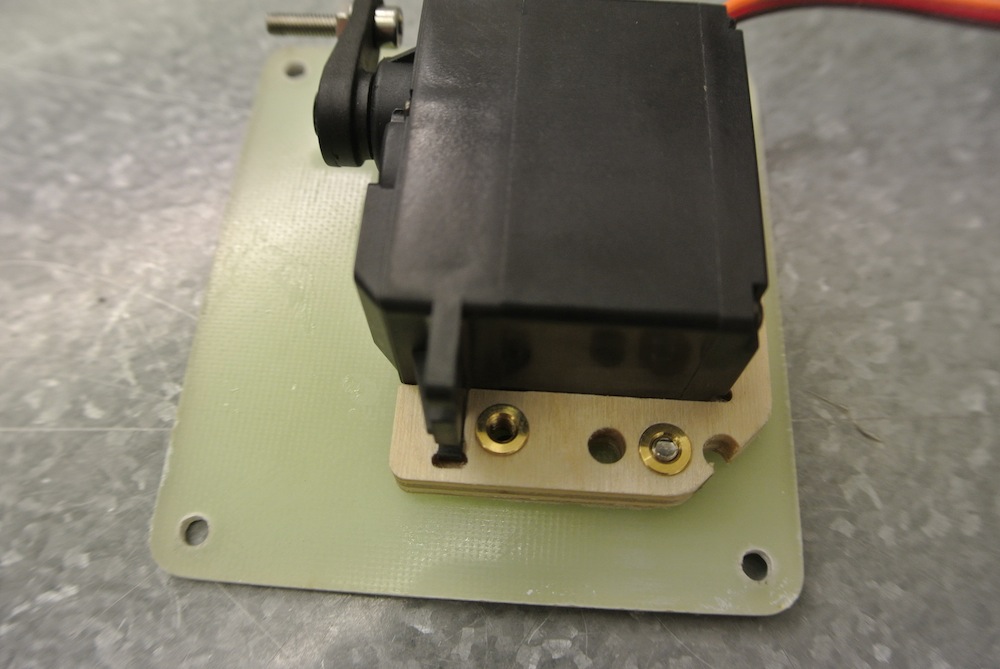
Flap Linkage
The flaps are driven via an internal linkage commonly seen on many larger jets, the horns a cnc'd carbon and are glued into slots pre-cut in the flap structure, I chose the ball link and bolted this through the two horns before preparing for gluing to make sure the gap was set right. I also angled the horns slightly towards the top surface as this makes for a better leverage on the flap seeing as its live hinged on the bottom.
My dilemma with the flap servo was how best to mount it, I was keen to mount it to the top wing skin but felt this might not really be the right way as although the surface area being glued (using my wooden servo dock accessories) is large the skin is not really structural. Mounting to the servo cover which is a 1.6mm G10 plate would be better as the cover locates onto ply formers which surround the servo opening and provide the bolt holes to secure the cover. After some head scratching I decided to mount the servo on the cover, the more tricky part to this method is setting the correct location for the servo in respect of the linkage etc but a little juggling resulted in the location marked up.
I did not have any more of the aluminium servo mounts left, 4 were supplied so will advise that 6 are included in the production kits, so used my servo dock which turned out to work well. It need the corners trimmed a little to avoid the corners of the servo hatch where the bolts went. I used two of the glue seep holes to insert small M3 blind nut inserts so the plate is held in place by bolts passing through the top of the cover, it meant no glue was needed which in the case of mounting servos is in my opinion a good move.
The two holes in the servo dock which normally take the servo security strap will be used as the 3rd and 4th fixing points and I have ordered some 30mm long bolts that will not only bolt the base of the servo dock to the servo cover but extend up and allow the security strap to be fixed as well holding the servo well in place.
The linkage can be attached to the servo arm easily before placing the cover in place and fixing it down with the 4 M3 bolts.
Servo is a JR8511 with a short 14mm centred arm. I used the 72mm long turnbuckles to make up the linkages which gave a nice overall length.
Electron Gear Modification.
Now the nose gear is almost done I tackled the main gear starting with one wing as the dummy....
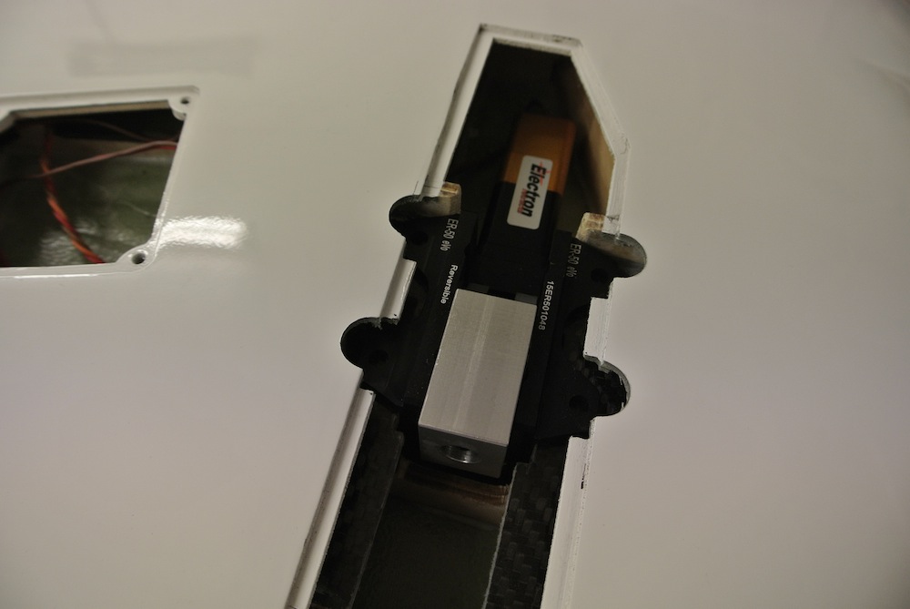
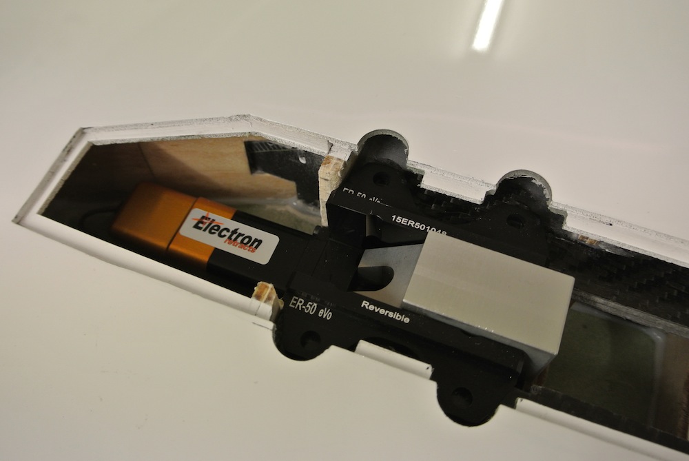
The rails fitted like in the nose need to be opened out, its only 4mm extra each side so marked the rails and sparked up the Proxxon with various carbide rotary attachments, once the rails were opened out the former under the rails needed some material removed as the Electrons are deeper than the pneumatic gear set. Again more surgery with abrasive tools.
The fixing lugs on the Electrons are also naturally wider as a result of the wider retract unit, I could not find a way to slide the retract onto the rails so reluctantly sanded 4 semi-circular cut-outs in the skin to allow the lugs to pass through for fixing, I might just leave them or re-make the cover plate (which will need the slot opening out) to match the new opening + cut-outs.
The Electron now sits nicely in the wing, below the skin so the leg covers should also fit.
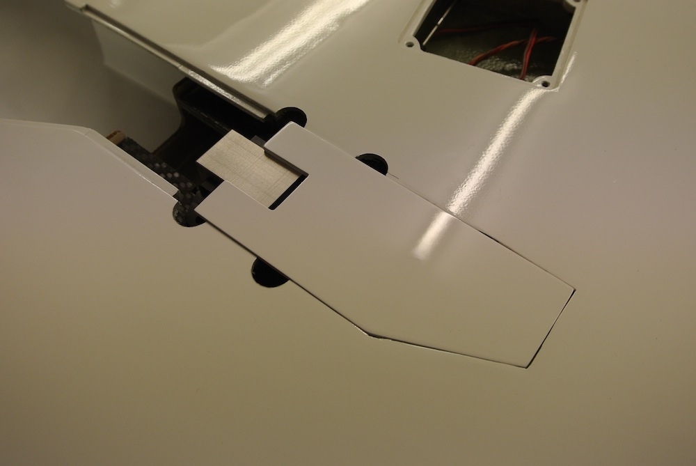
Next job is fixing the final main leg length based on the retract position and the wheel well cut-out. Just for info the wheel wells are enclosed, I have added a picture of this as its a nice touch and makes for a cleaner look.

marcs
The flaps are driven via an internal linkage commonly seen on many larger jets, the horns a cnc'd carbon and are glued into slots pre-cut in the flap structure, I chose the ball link and bolted this through the two horns before preparing for gluing to make sure the gap was set right. I also angled the horns slightly towards the top surface as this makes for a better leverage on the flap seeing as its live hinged on the bottom.
My dilemma with the flap servo was how best to mount it, I was keen to mount it to the top wing skin but felt this might not really be the right way as although the surface area being glued (using my wooden servo dock accessories) is large the skin is not really structural. Mounting to the servo cover which is a 1.6mm G10 plate would be better as the cover locates onto ply formers which surround the servo opening and provide the bolt holes to secure the cover. After some head scratching I decided to mount the servo on the cover, the more tricky part to this method is setting the correct location for the servo in respect of the linkage etc but a little juggling resulted in the location marked up.
I did not have any more of the aluminium servo mounts left, 4 were supplied so will advise that 6 are included in the production kits, so used my servo dock which turned out to work well. It need the corners trimmed a little to avoid the corners of the servo hatch where the bolts went. I used two of the glue seep holes to insert small M3 blind nut inserts so the plate is held in place by bolts passing through the top of the cover, it meant no glue was needed which in the case of mounting servos is in my opinion a good move.
The two holes in the servo dock which normally take the servo security strap will be used as the 3rd and 4th fixing points and I have ordered some 30mm long bolts that will not only bolt the base of the servo dock to the servo cover but extend up and allow the security strap to be fixed as well holding the servo well in place.
The linkage can be attached to the servo arm easily before placing the cover in place and fixing it down with the 4 M3 bolts.
Servo is a JR8511 with a short 14mm centred arm. I used the 72mm long turnbuckles to make up the linkages which gave a nice overall length.
Electron Gear Modification.
Now the nose gear is almost done I tackled the main gear starting with one wing as the dummy....
The rails fitted like in the nose need to be opened out, its only 4mm extra each side so marked the rails and sparked up the Proxxon with various carbide rotary attachments, once the rails were opened out the former under the rails needed some material removed as the Electrons are deeper than the pneumatic gear set. Again more surgery with abrasive tools.
The fixing lugs on the Electrons are also naturally wider as a result of the wider retract unit, I could not find a way to slide the retract onto the rails so reluctantly sanded 4 semi-circular cut-outs in the skin to allow the lugs to pass through for fixing, I might just leave them or re-make the cover plate (which will need the slot opening out) to match the new opening + cut-outs.
The Electron now sits nicely in the wing, below the skin so the leg covers should also fit.
Next job is fixing the final main leg length based on the retract position and the wheel well cut-out. Just for info the wheel wells are enclosed, I have added a picture of this as its a nice touch and makes for a cleaner look.
marcs
08-03-2015, 03:56 AM
#33
Thread Starter
Join Date: Jan 2007
Location: farnborough, , UNITED KINGDOM
Posts: 3,294
Likes: 0
Received 1 Like
on
1 Post
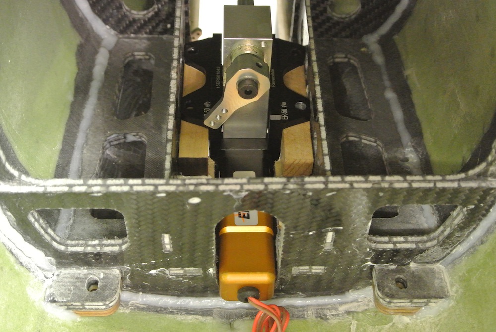
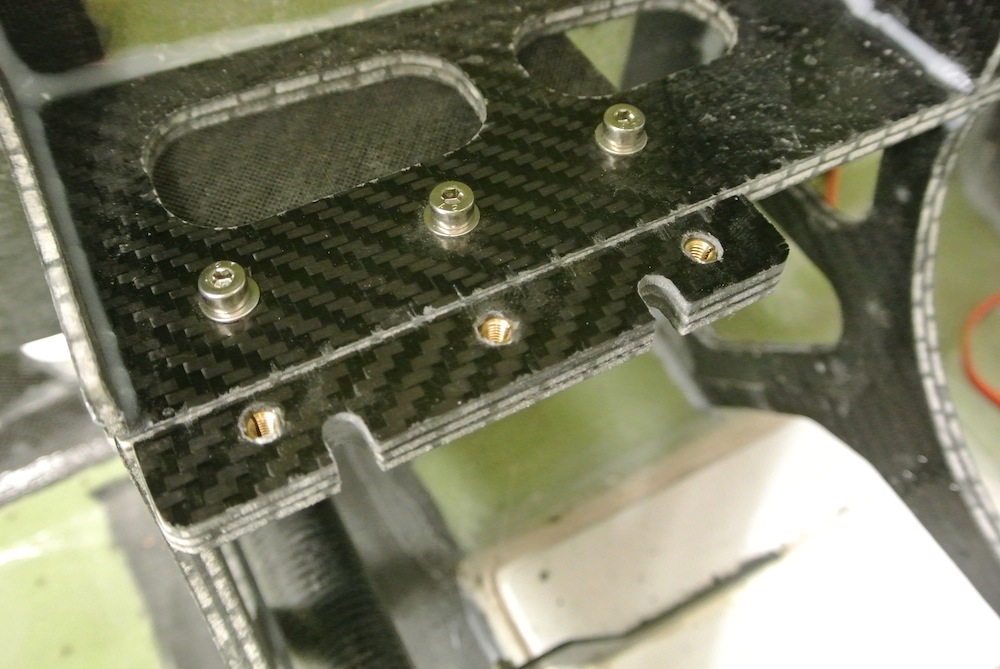
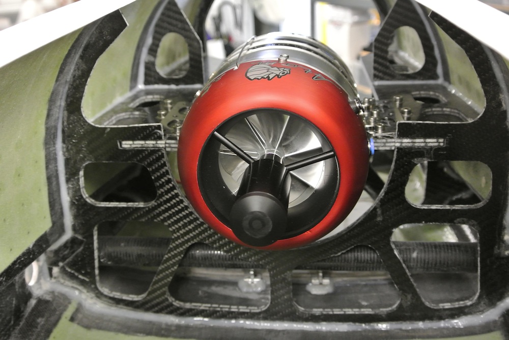
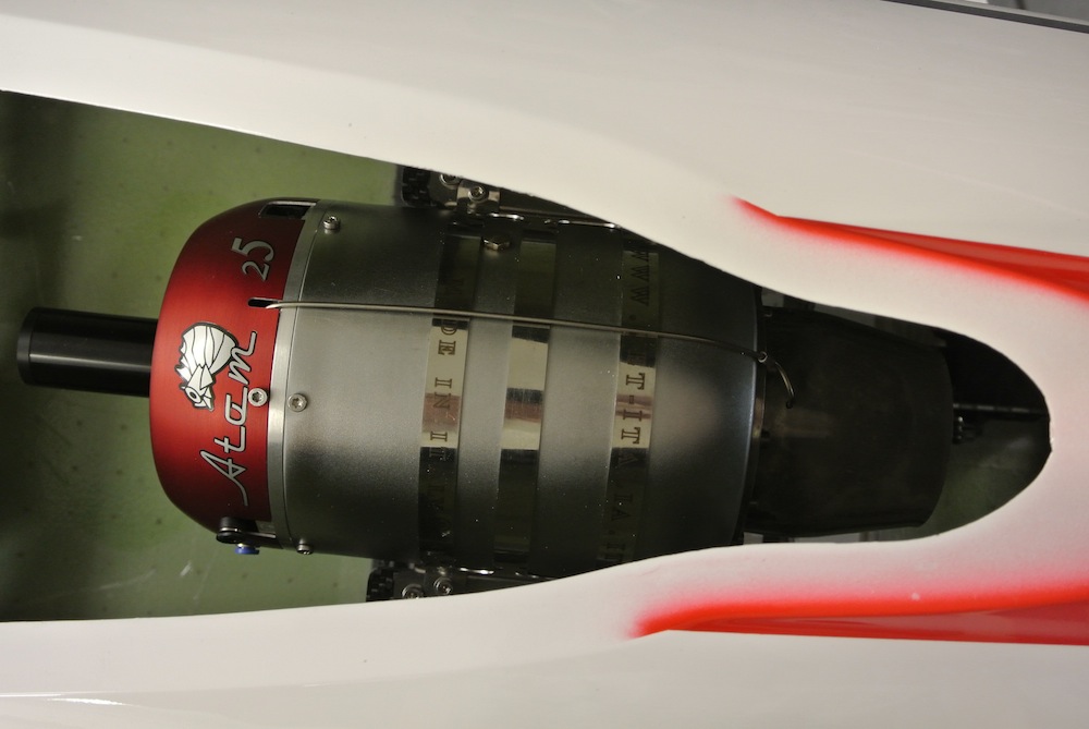
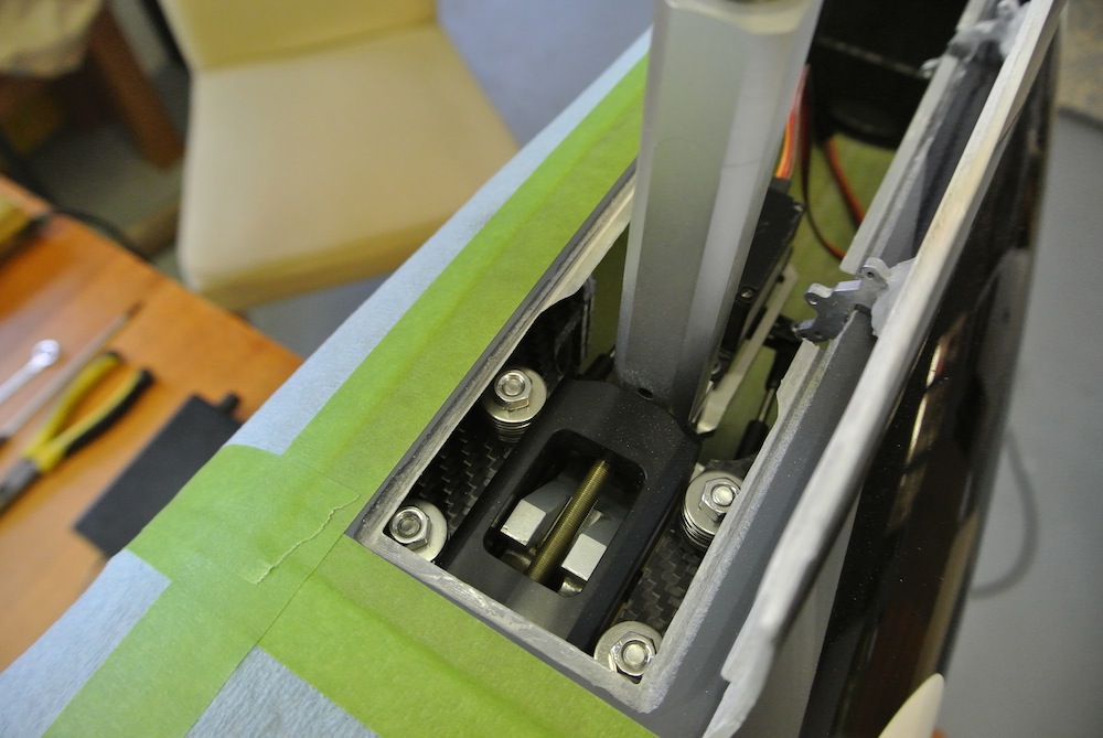
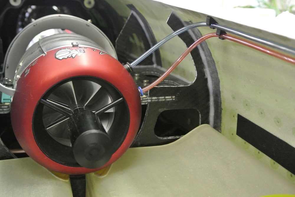
Turbine Mounting
The formers fitted to the Vixen are designed to take the carbon bypass which is supplied as part of the kit and as I have decided to mount the turbine without the bypass primarily to keep the weight down as the regs in Germany where I hope the Vixen will fly in September are tight. I will instal the bypass after the event as I much prefer this set up.
To manage the width of the Atom 25 mounting brackets I had to make extension plates to bridge the gap between the former rails, this was done by making up adapter plates from the same carbon plate used in the Vixen formers to give the desired support. They are bolted to the fitted rails with 6 x M4 bolts so they can be removed when the carbon bypass is added at a later date.
The turbine is positioned nicely so that access is easy both from the canopy opening and the rear access made possible by the split fuselage.
I installed threaded inserts on the extension rails where the turbine straps are located to make it easier to fit as gutting nuts on the underside of these bolts when the turbine was in place was a tad tricky!

Gear
Almost sorted the new double arm tiller for the nose steering, once done will post the final linkage connections and will mount this in the nose section. The main gear has been modified and now the leg/wheels fit perfectly in the space allocated, I had to remove 16mm from the leg length as the gear supplied by Electron for this jet was judged from the drawing and so I expected there to be some 'tweaks' here and there. Pics to follow.
marcs
The formers fitted to the Vixen are designed to take the carbon bypass which is supplied as part of the kit and as I have decided to mount the turbine without the bypass primarily to keep the weight down as the regs in Germany where I hope the Vixen will fly in September are tight. I will instal the bypass after the event as I much prefer this set up.
To manage the width of the Atom 25 mounting brackets I had to make extension plates to bridge the gap between the former rails, this was done by making up adapter plates from the same carbon plate used in the Vixen formers to give the desired support. They are bolted to the fitted rails with 6 x M4 bolts so they can be removed when the carbon bypass is added at a later date.
The turbine is positioned nicely so that access is easy both from the canopy opening and the rear access made possible by the split fuselage.
I installed threaded inserts on the extension rails where the turbine straps are located to make it easier to fit as gutting nuts on the underside of these bolts when the turbine was in place was a tad tricky!
Gear
Almost sorted the new double arm tiller for the nose steering, once done will post the final linkage connections and will mount this in the nose section. The main gear has been modified and now the leg/wheels fit perfectly in the space allocated, I had to remove 16mm from the leg length as the gear supplied by Electron for this jet was judged from the drawing and so I expected there to be some 'tweaks' here and there. Pics to follow.
marcs
08-03-2015, 12:18 PM
#34
My Feedback: (33)
Join Date: Feb 2002
Location: Chicago, IL
Posts: 469
Likes: 0
Received 0 Likes
on
0 Posts
Marc,
Just a little concerned about the compression strength of the sandwiched carbon and the inner white material. Just from the pictures the mounting plates appear to have good torsional strength but not sure about the compression resistance. I suspect the other Xtreme Jets out there using this material are having no issues. I haven't heard of any issues just curiosity getting the best of me.
Thanks
Keith
08-03-2015, 01:01 PM
#35
Thread Starter
Join Date: Jan 2007
Location: farnborough, , UNITED KINGDOM
Posts: 3,294
Likes: 0
Received 1 Like
on
1 Post
The compression ability of this sandwich material is pretty good, I have fitted very large diameter penny washers on the underside so the loads are spread over 3/4 of an inch or so and the turbine plate provides its own distribution of pressure.
marcs
marcs
08-04-2015, 04:41 AM
#37
Thread Starter
Join Date: Jan 2007
Location: farnborough, , UNITED KINGDOM
Posts: 3,294
Likes: 0
Received 1 Like
on
1 Post
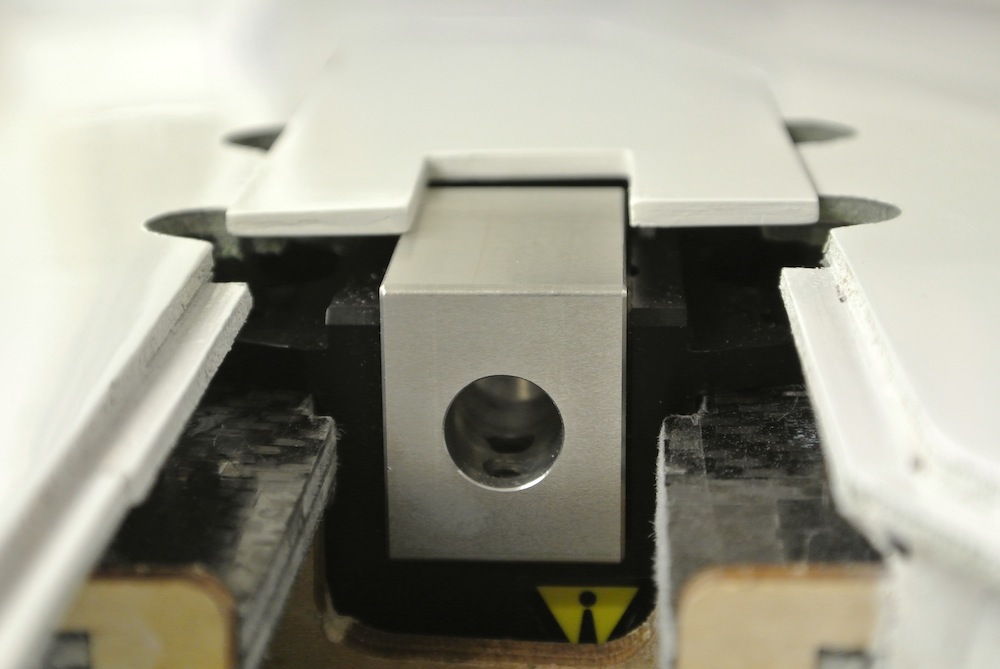
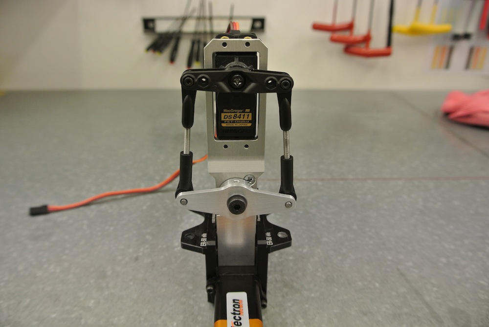
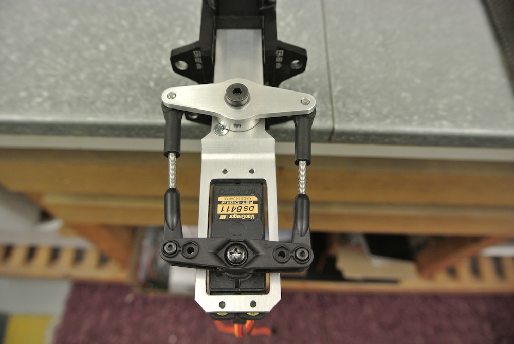
Nose Wheel Steering
The original tiller is a one arm product, which in most circumstances is going to be perfect, for me I like the security of a pull pull system so had a friend machine up a new double arm version so I could use the steering in a pull pull method, a simple swap and works really nice and smooth.
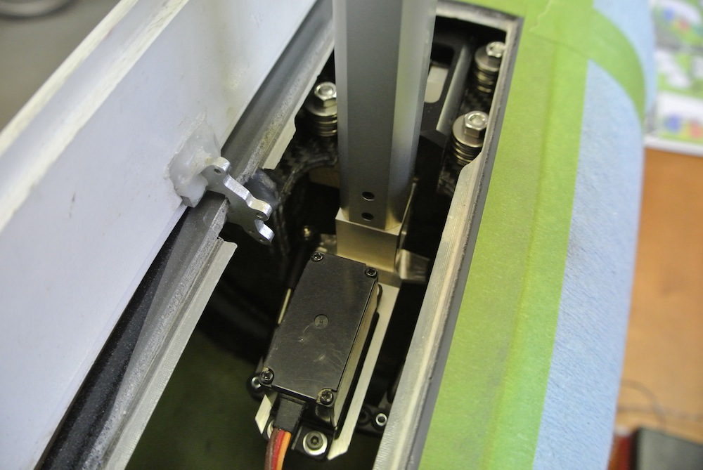
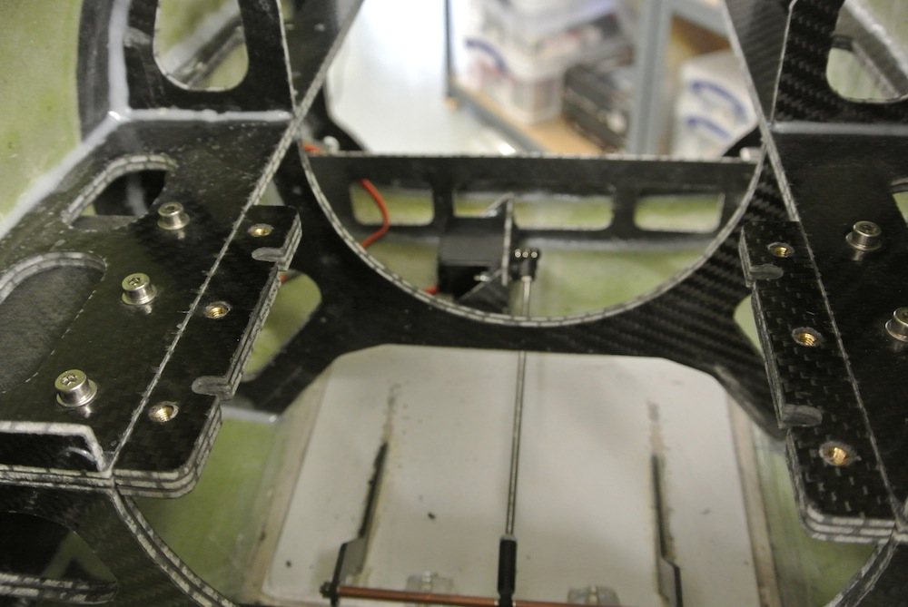
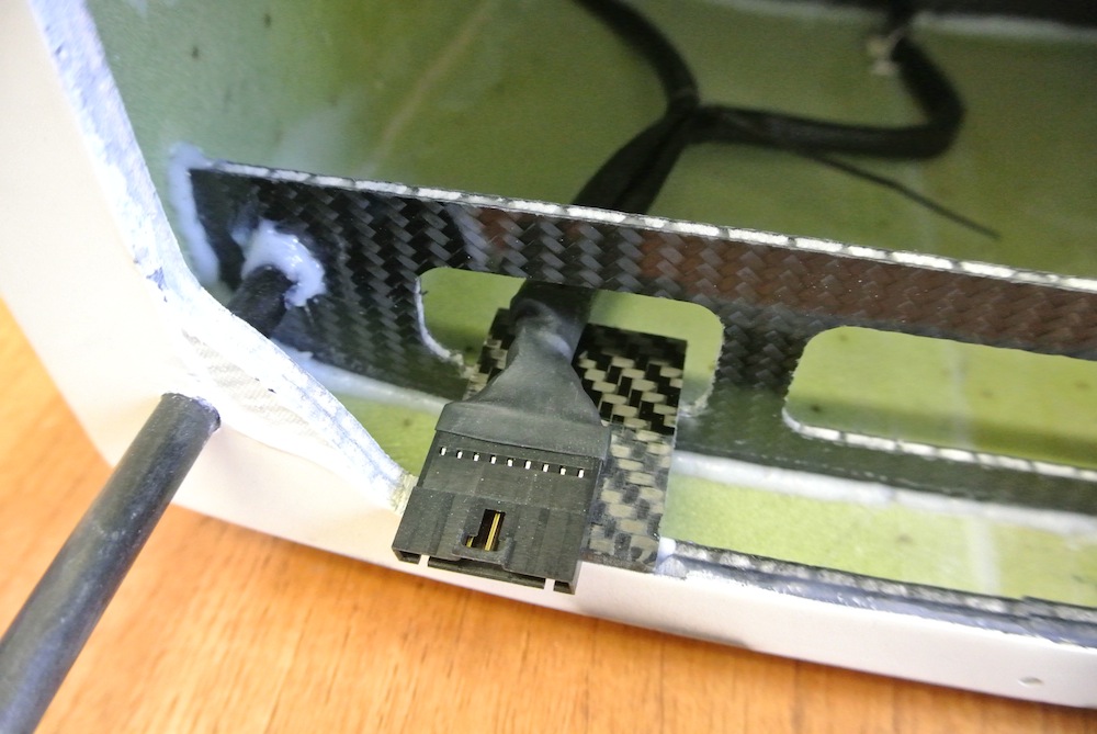
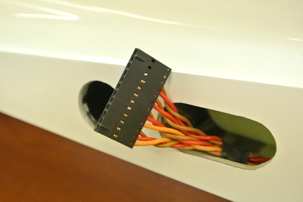
Fuselage
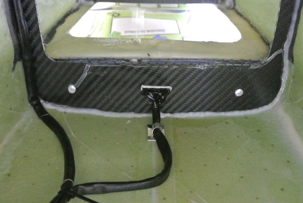
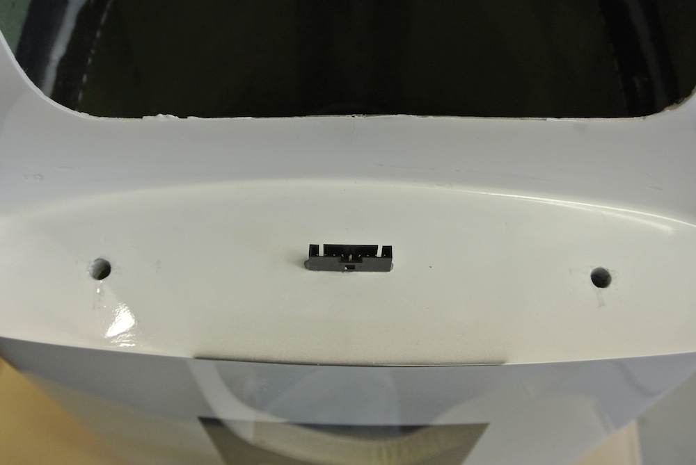
Started to work on the internal wiring for the fuselage sections, in the tail section I wired to the rudder post and fitted a connector so the servo lead from the rudder can connect up, this terminated at a 9 way Ashlok along with the two feeds back from the elevators. For the elevator connection I decided to hard fix another Ashlok onto the front engagement plate for the stab unit so that when the stab is connected no loose wires are inside the fuselage where then might contact hot surfaces, instead they will float around inside the stab unit away from harms way.
The rear fuselage section connection Ashok will be mounted onto the small flat plate I glued onto the mating face, this then connects to a flying lead exiting at the rear of the main fuselage.
marcs
The original tiller is a one arm product, which in most circumstances is going to be perfect, for me I like the security of a pull pull system so had a friend machine up a new double arm version so I could use the steering in a pull pull method, a simple swap and works really nice and smooth.
Fuselage
Started to work on the internal wiring for the fuselage sections, in the tail section I wired to the rudder post and fitted a connector so the servo lead from the rudder can connect up, this terminated at a 9 way Ashlok along with the two feeds back from the elevators. For the elevator connection I decided to hard fix another Ashlok onto the front engagement plate for the stab unit so that when the stab is connected no loose wires are inside the fuselage where then might contact hot surfaces, instead they will float around inside the stab unit away from harms way.
The rear fuselage section connection Ashok will be mounted onto the small flat plate I glued onto the mating face, this then connects to a flying lead exiting at the rear of the main fuselage.
marcs
08-05-2015, 01:30 AM
#38
Thread Starter
Join Date: Jan 2007
Location: farnborough, , UNITED KINGDOM
Posts: 3,294
Likes: 0
Received 1 Like
on
1 Post
Thrust Pipe
The pipe supplied is well made and dual walled, it was measured to fit the Vixen WITHOUT the bypass so this works for my current build however it will need to be around 95mm shorter to work when the bypass is installed so this info has been passed back to Wagner and the guys at Xtreme ARF.
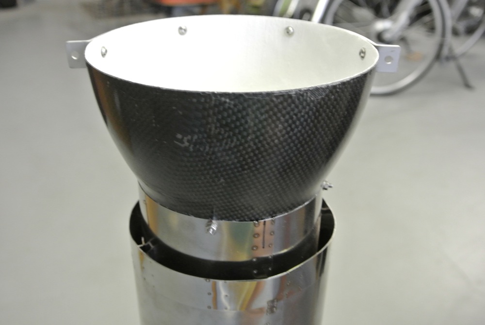
The bell mouth is carbon moulded and the first job was to mark it up and fit it too the thrust pipe. I guess I'm not the only one who hates drilling stainless steel but I have found a neat way of doing it easier rather than fighting with blunt drill bits.
First mark up the location of the holes, to get this even I wrap a piece of masking tape round the pipe, mark the overlap, remove and divide up the length with the amount of holes you need then re-apply the tape and use the marks as the points to drill. So here is the method I use.
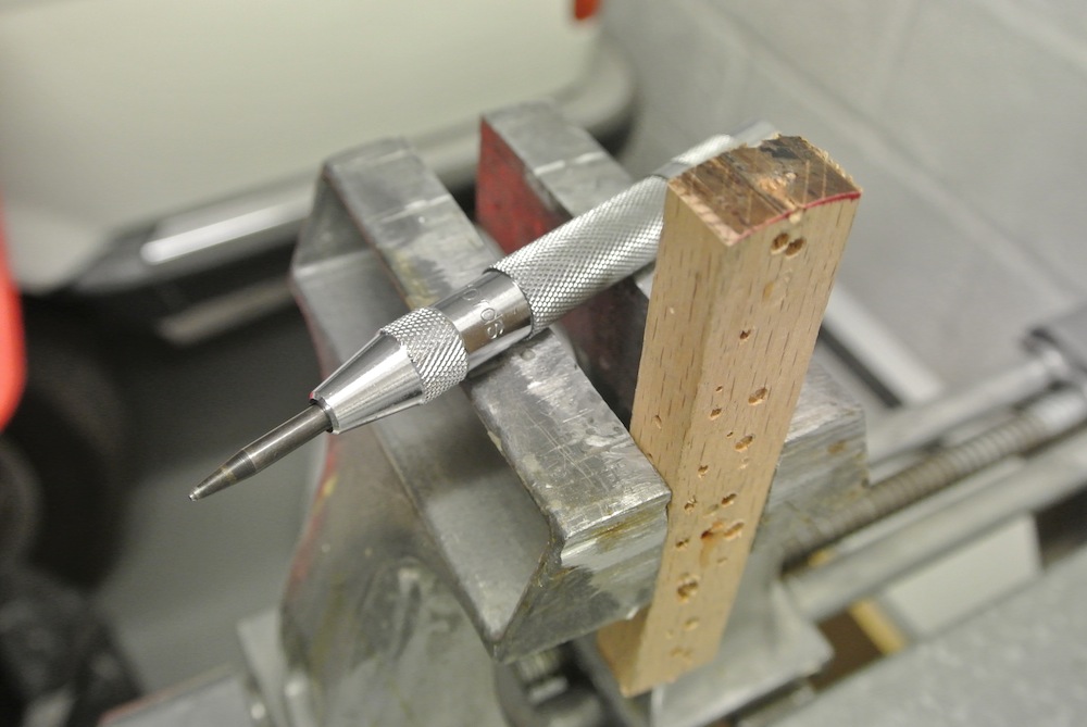
Grab an off cut of hard wood and band saw it so one end is curved to mimic the inside curve of the pipe to be drilled, hold the pipe on this curved wooden jig where you want to make the hole, take a sprung punch tool and indent the pipe where you want the hole. The wooden jig will stop the pipe moving while the punch pops a neat hole right through the stainless steel, this can then easily be opened up with the drill of your choice - saves a lot of time and hassle.
With the pipe drilled and the bell mouth set up I also made the fixing strap for the pipe, this is a piece of aluminium flat which I curve round an old tin to get the shape, then make two tabs which locate on the turbine rail formers (having perviously marked the locations for the tabs), drill the strap to fix to the bell mouth and set aside.
Four coats of BVM Ceramic Heat Shield on the bell mouth will help with heat, once dry the assembly is bolted together with M3 fixings.
Ready to fit in place once the tail section is ready...


Wooden jig and sprung punch.
marcs
The pipe supplied is well made and dual walled, it was measured to fit the Vixen WITHOUT the bypass so this works for my current build however it will need to be around 95mm shorter to work when the bypass is installed so this info has been passed back to Wagner and the guys at Xtreme ARF.
The bell mouth is carbon moulded and the first job was to mark it up and fit it too the thrust pipe. I guess I'm not the only one who hates drilling stainless steel but I have found a neat way of doing it easier rather than fighting with blunt drill bits.
First mark up the location of the holes, to get this even I wrap a piece of masking tape round the pipe, mark the overlap, remove and divide up the length with the amount of holes you need then re-apply the tape and use the marks as the points to drill. So here is the method I use.
Grab an off cut of hard wood and band saw it so one end is curved to mimic the inside curve of the pipe to be drilled, hold the pipe on this curved wooden jig where you want to make the hole, take a sprung punch tool and indent the pipe where you want the hole. The wooden jig will stop the pipe moving while the punch pops a neat hole right through the stainless steel, this can then easily be opened up with the drill of your choice - saves a lot of time and hassle.
With the pipe drilled and the bell mouth set up I also made the fixing strap for the pipe, this is a piece of aluminium flat which I curve round an old tin to get the shape, then make two tabs which locate on the turbine rail formers (having perviously marked the locations for the tabs), drill the strap to fix to the bell mouth and set aside.
Four coats of BVM Ceramic Heat Shield on the bell mouth will help with heat, once dry the assembly is bolted together with M3 fixings.
Ready to fit in place once the tail section is ready...
Wooden jig and sprung punch.
marcs
08-14-2015, 12:55 AM
#39
Thread Starter
Join Date: Jan 2007
Location: farnborough, , UNITED KINGDOM
Posts: 3,294
Likes: 0
Received 1 Like
on
1 Post
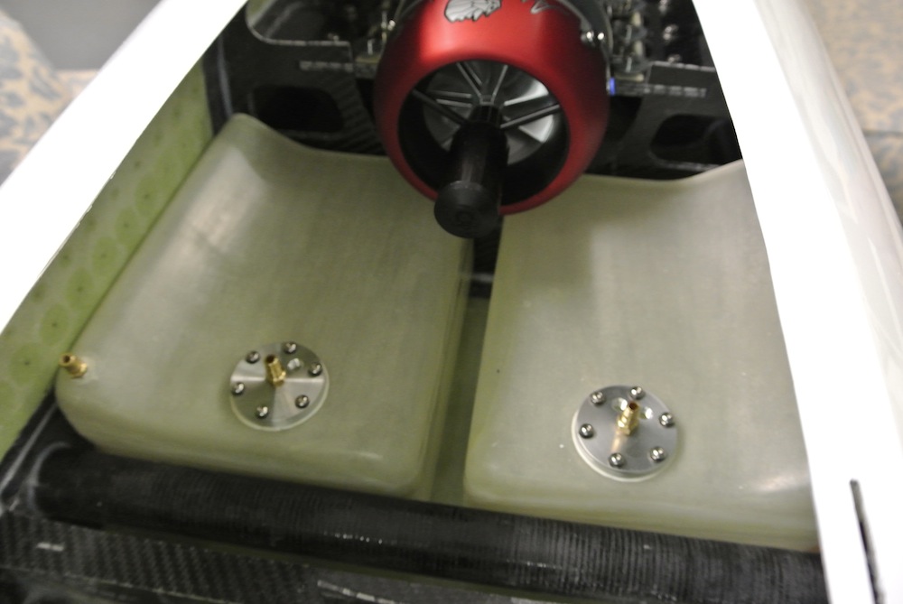
Been waiting for some parts to arrive from various places to complete some of the instal so over the last week or so have been working on the fuel tanks.
When I say working let me explain. The prototype Vixen ran two large saddle tanks and a hopper amounting to around 9L of fuel capacity, the saddle tanks were long and as a result of fuel movement were also baffled. My view was they were too big and I don't like long fuel tanks for many reasons either. It has been decided to reduce the capacity of the tanks to around 6L for the two saddle tanks and a 1L hopper which gives 7L in total with a further 1L for smoke if required. This should result in the saddle tanks being more 'square' in shape, it allows them to sit almost centrally over the CG location and means no baffles are required.
Wagner is kindly working on the new moulds to make these as we speak.
For my Vixen and the deadline to have the jet ready to fly at Jetpower I have decided to 'modify' the original long tanks by literally chopping off around a third of them. The plan was to chop them to a length that allowed them to fit in the space between the wing tubes. I cut them down and then made two FR4 plates to fit the cut ends, prepped the surfaces and glued with Hysol. Once cured I sanded the seams flush and then added a strip of glass fibre cloth around the seam to strengthen.
In Germany the weight rule is 25kg wet, so the tanks have to be full which also means I did not want them to be oversized, the result is around 2.5L each which gives 5L capacity, the turbine runs at 760cc/m max power so at full throttle this will give 6.5 mins of run time, I expect the actual throttle to be half for most of the flying time so this should deliver a safe 5-6 mins of flying time.
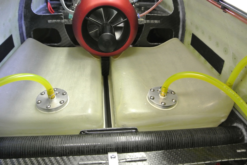
Added my own filler hardware and will plumb over the next few days once some fittings arrive from my cnc shop.
Fitted out a simple equipment tray and will now start to make up the leads and servo cables to suit.

marcs
When I say working let me explain. The prototype Vixen ran two large saddle tanks and a hopper amounting to around 9L of fuel capacity, the saddle tanks were long and as a result of fuel movement were also baffled. My view was they were too big and I don't like long fuel tanks for many reasons either. It has been decided to reduce the capacity of the tanks to around 6L for the two saddle tanks and a 1L hopper which gives 7L in total with a further 1L for smoke if required. This should result in the saddle tanks being more 'square' in shape, it allows them to sit almost centrally over the CG location and means no baffles are required.
Wagner is kindly working on the new moulds to make these as we speak.
For my Vixen and the deadline to have the jet ready to fly at Jetpower I have decided to 'modify' the original long tanks by literally chopping off around a third of them. The plan was to chop them to a length that allowed them to fit in the space between the wing tubes. I cut them down and then made two FR4 plates to fit the cut ends, prepped the surfaces and glued with Hysol. Once cured I sanded the seams flush and then added a strip of glass fibre cloth around the seam to strengthen.
In Germany the weight rule is 25kg wet, so the tanks have to be full which also means I did not want them to be oversized, the result is around 2.5L each which gives 5L capacity, the turbine runs at 760cc/m max power so at full throttle this will give 6.5 mins of run time, I expect the actual throttle to be half for most of the flying time so this should deliver a safe 5-6 mins of flying time.
Added my own filler hardware and will plumb over the next few days once some fittings arrive from my cnc shop.
Fitted out a simple equipment tray and will now start to make up the leads and servo cables to suit.
marcs
08-14-2015, 04:15 AM
#41
Thread Starter
Join Date: Jan 2007
Location: farnborough, , UNITED KINGDOM
Posts: 3,294
Likes: 0
Received 1 Like
on
1 Post
Geoff,
Thank you, the fittings were on my site but due to pressures of jobs and Jetpower I have had to focus on CAT's and Maglok products so the Pro-Filler is currently not a stock item.
marcs
Thank you, the fittings were on my site but due to pressures of jobs and Jetpower I have had to focus on CAT's and Maglok products so the Pro-Filler is currently not a stock item.
marcs

 08-21-2015, 04:29 AM
#45
Thread Starter
Join Date: Jan 2007
Location: farnborough, , UNITED KINGDOM
Posts: 3,294
Likes: 0
Received 1 Like
on
1 Post
Hi sorry for the delay in posting, with a lack of time before Jetpower I have had to leave the camera on the table for now but did have 5 mins to take a few updates...
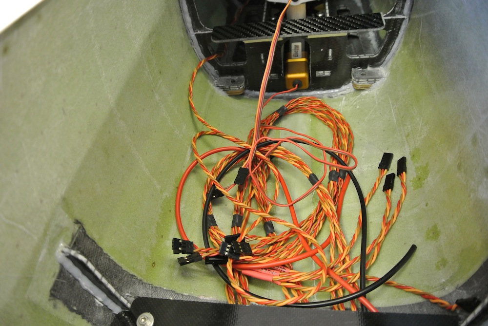
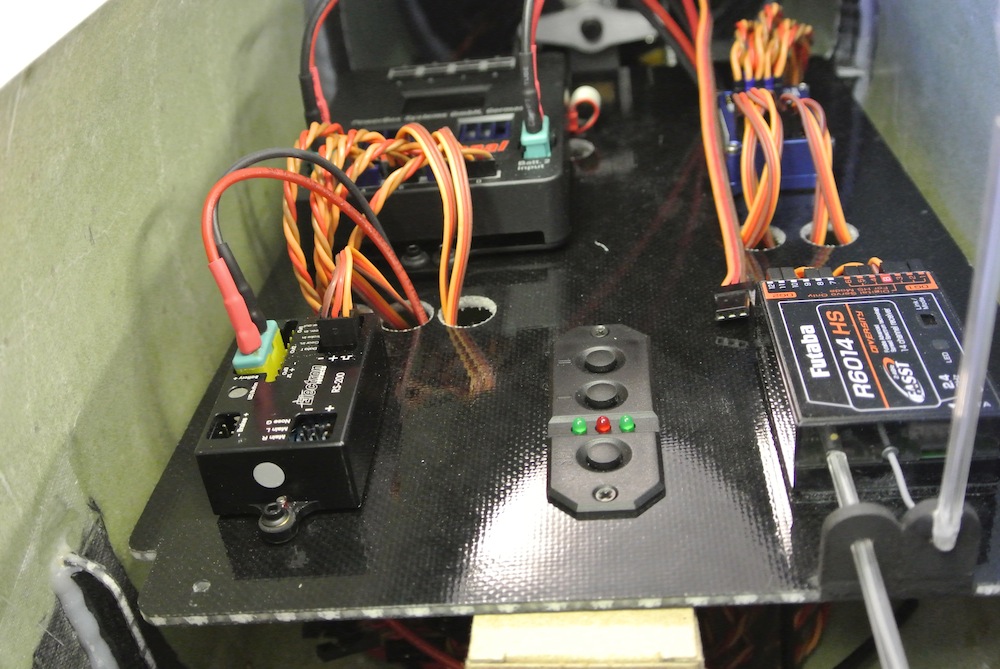
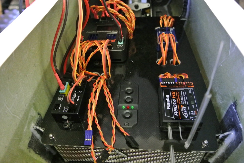
Made up all the leads to connect the rear systems to the front area where the equipment is located, I wired the wing connectors using Ashlok's as these have been great connectors in the past and I like the way they locate and have a safety locking tab.
Tail is all sorted with the 8411's mounted, there is very little room for these servo's let along bigger cased units so may discuss this with the factory to slightly move the servo location to give a little more depth. Two M3 bolts hold the rear stab in place with the threaded nuts very securely mounted on a carbon reinforced ply former bridging the aft fuselage.
I had a little re-jig of the equipment boards but with so much space its really a nice job to play around with these components to get a simple and relatively neat layout - everything is easily got to and easy to connect - which is very nice
Tanks are awaiting some special barbs before I will remove them a fully test them for leaks before final installation. Using velcro and plates to hold the tanks down and will make a bracket of some form to hold the other sides secure.
Weighed all the components and she is currently at 18.4kg, so with batteries and balance maybe around 19-19.5kg. German rules state 25kg fully fuelled so with 5L of Kero which is approx 4kg the AUW should be no more than 23.5kg which is good news.
marcs
09-04-2015, 03:56 AM
#46
Thread Starter
Join Date: Jan 2007
Location: farnborough, , UNITED KINGDOM
Posts: 3,294
Likes: 0
Received 1 Like
on
1 Post
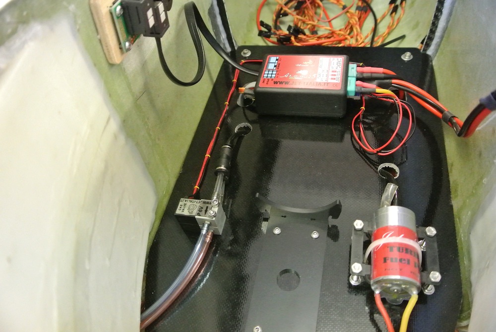
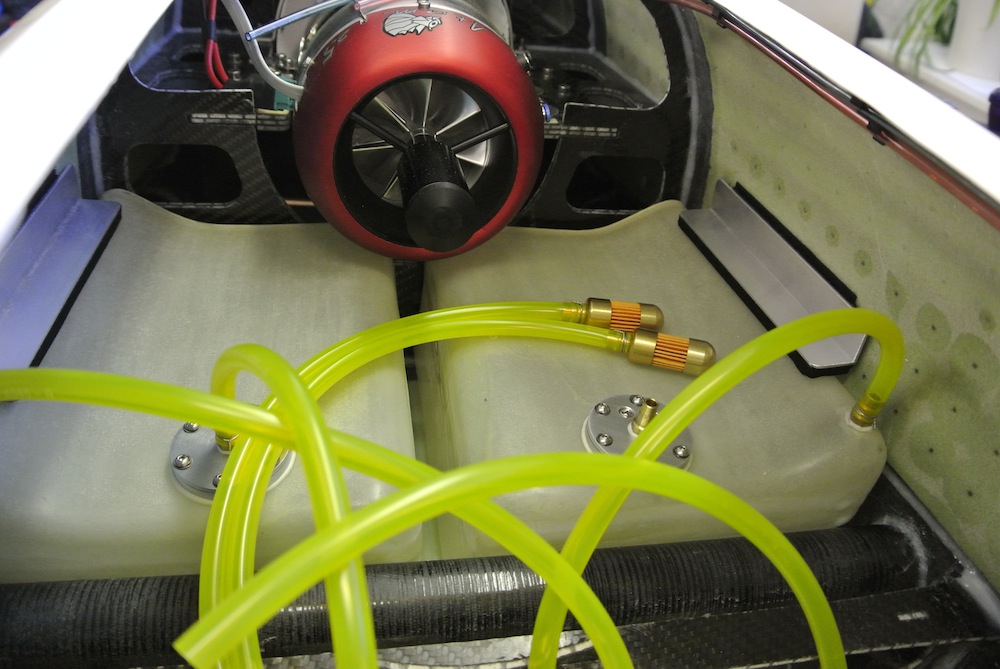
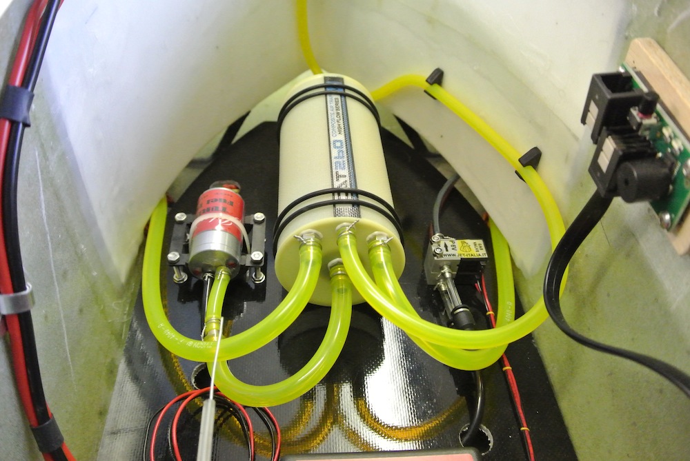
Just a few shots of the final equipment instal, with plenty of space its a nice easy job, two trays split between mainly fuel/turbine and receiver/PB/gyro with space below the upper deck to have plenty of space for wiring to be hidden.
I added the ali plate between the two plates to prevent wires moving about in flight.
Twin tanks are plumbed directly into a one of my CAT-L's with two tank inputs, omly one decision left and that is do I run one vent with a T to the two tanks or twin vents - whats the better solution?
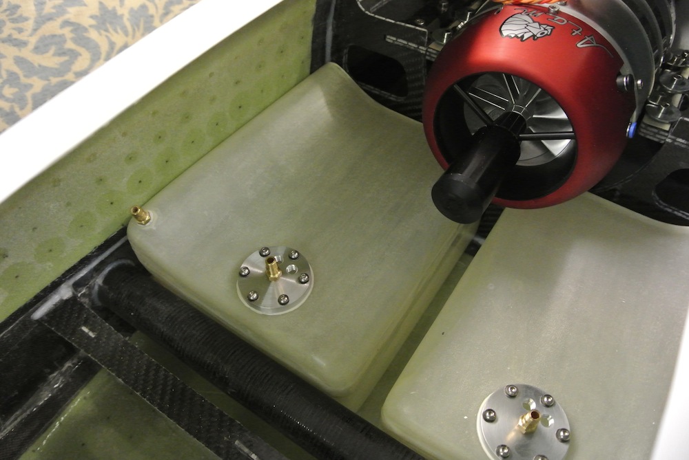
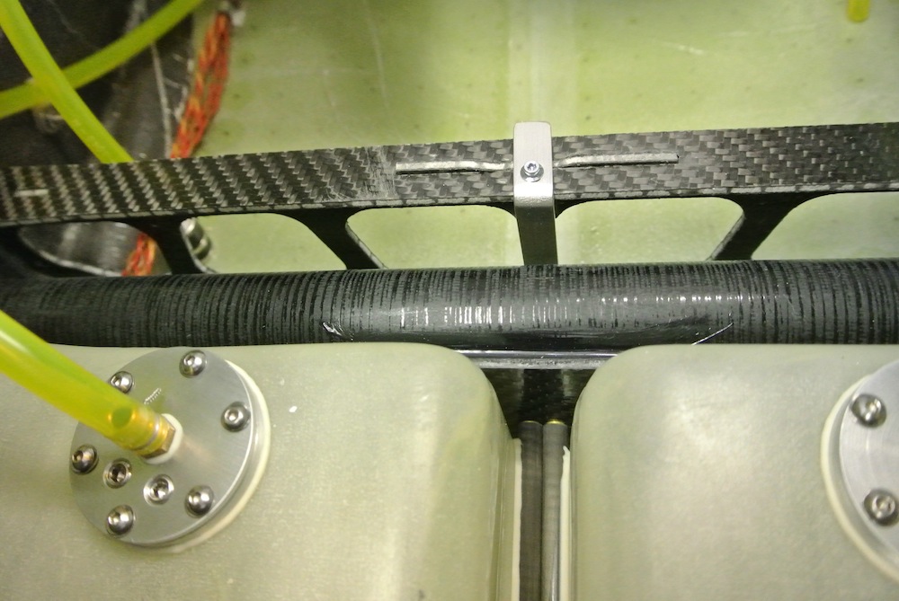
One task which often can cause issues is mounting tanks, in this installation I used a similar method used on a CARF Eurosport - brass tubes.
I glued along one straight edge of the tank a tube, in this case its an old carbon arrow shaft which a friend gives me when the tips are damaged, they are very light and strong (ali tube with a carbon outer), this tube takes a brass tube inside which slides through a plate with holes drilled to match the brass tubes and through the tubes glued to the tank sides and then through another plate at the end of the tank. In this installation one plate was glued to the former which supports the turbine rails, and the front plate is glued to the main wing tube sleeve and also to the base of the fuselage. A small bent aluminium retainer prevent the brass tubes sliding forwards and as the ends are flattened they cannot slide backwards. To remove the tanks is a simple matter of removing the screw holding the retainer and sliding the two brass tubes forwards - takes 20 seconds at most and provides a very permanent fix with good strength as the tube glued to the tank runs the full tank length. The retainer and plate are visible in picture 2.
Planning to maiden on the 11th in time for Jetpower so a very tight schedule and fingers crossed the weather is kind and all hangs together!
marcs
I added the ali plate between the two plates to prevent wires moving about in flight.
Twin tanks are plumbed directly into a one of my CAT-L's with two tank inputs, omly one decision left and that is do I run one vent with a T to the two tanks or twin vents - whats the better solution?
One task which often can cause issues is mounting tanks, in this installation I used a similar method used on a CARF Eurosport - brass tubes.
I glued along one straight edge of the tank a tube, in this case its an old carbon arrow shaft which a friend gives me when the tips are damaged, they are very light and strong (ali tube with a carbon outer), this tube takes a brass tube inside which slides through a plate with holes drilled to match the brass tubes and through the tubes glued to the tank sides and then through another plate at the end of the tank. In this installation one plate was glued to the former which supports the turbine rails, and the front plate is glued to the main wing tube sleeve and also to the base of the fuselage. A small bent aluminium retainer prevent the brass tubes sliding forwards and as the ends are flattened they cannot slide backwards. To remove the tanks is a simple matter of removing the screw holding the retainer and sliding the two brass tubes forwards - takes 20 seconds at most and provides a very permanent fix with good strength as the tube glued to the tank runs the full tank length. The retainer and plate are visible in picture 2.
Planning to maiden on the 11th in time for Jetpower so a very tight schedule and fingers crossed the weather is kind and all hangs together!
marcs

