


US NAVY SeaDart F2Y (Flying boat) Build
 05-09-2017, 06:01 PM
#226

My Feedback: (6)
You betcha don't know if any one knows what a design lofting floor is but in those days it was a hard wood floor about 25 ft. wide and about 150 long with an camera on a rolling gantry, special sheets of steel that were coated with a white type paint and all parts were drawn by hand on them, ( you had to dress much like in a clean room today no shoes ) then photo grafted so the layout could be copied into blue prints 9 Line drawings ), the lines on the first prints were about .002 wide. then detail drawings could be made from these line drawings.
Just an old mans thoughts
Cheers Bob T
Just an old mans thoughts
Cheers Bob T
 05-11-2017, 03:42 AM
#227


Join Date: Feb 2017
Location: UK
Posts: 4
Likes: 0
Received 0 Likes
on
0 Posts
Hi Guys,
The SeaDarts are progressing well and we hopefully have some good news surrounding the project but for the time being we're prohibited from posting any pictures. We hope this will change in the next month or two.
Many thanks
TLJC
The SeaDarts are progressing well and we hopefully have some good news surrounding the project but for the time being we're prohibited from posting any pictures. We hope this will change in the next month or two.
Many thanks
TLJC
09-21-2017, 12:48 AM
#228
Thread Starter

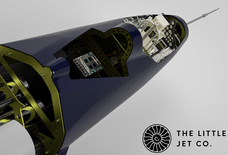
Finally we can get back to this thread. The CAD model is complete down to every component, ECU, TTU’s, batteries servos, actuators and so on… Everything has been modelled to ensure the best of fits. This in turn allows us to design a structure that can easily accommodate all the ancillary equipment. This also includes wiring looms and in this case electrical conduits have been designed in that double up as structural support. Things are further complicated by the nature of the model. This has been designed to operate solely from water so everything needs to be sealed. From the apertures that accommodate the gear and elevon actuators to a completely sealed bypassed ducting system.
 <script async src="//embedr.flickr.com/assets/client-code.js" charset="utf-8"></script>
 <script async src="//embedr.flickr.com/assets/client-code.js" charset="utf-8"></script>
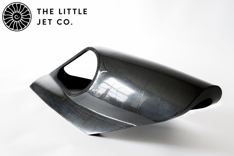
After much testing with various materials, layups, cycle times and pressures in the clave we have finally hit the sweet spot. All the components are now being manufactured with our composite partner who’s support in this project has gone well beyond what I had expected. The results are flawless so I’m very happy indeed. The composite parts are a mixture of monolithic layups, some components with core and some not. Various materials have been used including carbon, kevlar and e-glass. What we are doing that perhaps people may not have seen on an RC jet is that all the composite components are using pre-preg fabrics. This means we don’t have a gelcoat. Each component has the correct amount of resin pre-pregnated into the cloth as designed so you end up with the lightest yet strongest component possible. We have taken the time to get this just right as these techniques and materials will be used in our commercial projects next year which we very excited about.
 <script async src="//embedr.flickr.com/assets/client-code.js" charset="utf-8"></script>
Alex
TLJC
<script async src="//embedr.flickr.com/assets/client-code.js" charset="utf-8"></script><script async src="//embedr.flickr.com/assets/client-code.js" charset="utf-8"></script>After much testing with various materials, layups, cycle times and pressures in the clave we have finally hit the sweet spot. All the components are now being manufactured with our composite partner who’s support in this project has gone well beyond what I had expected. The results are flawless so I’m very happy indeed. The composite parts are a mixture of monolithic layups, some components with core and some not. Various materials have been used including carbon, kevlar and e-glass. What we are doing that perhaps people may not have seen on an RC jet is that all the composite components are using pre-preg fabrics. This means we don’t have a gelcoat. Each component has the correct amount of resin pre-pregnated into the cloth as designed so you end up with the lightest yet strongest component possible. We have taken the time to get this just right as these techniques and materials will be used in our commercial projects next year which we very excited about.
<script async src="//embedr.flickr.com/assets/client-code.js" charset="utf-8"></script>Alex
TLJC
09-21-2017, 01:08 AM
#229
Join Date: Feb 2017
Location: UK
Posts: 4
Likes: 0
Received 0 Likes
on
0 Posts
A quick reminder about the size of the model...
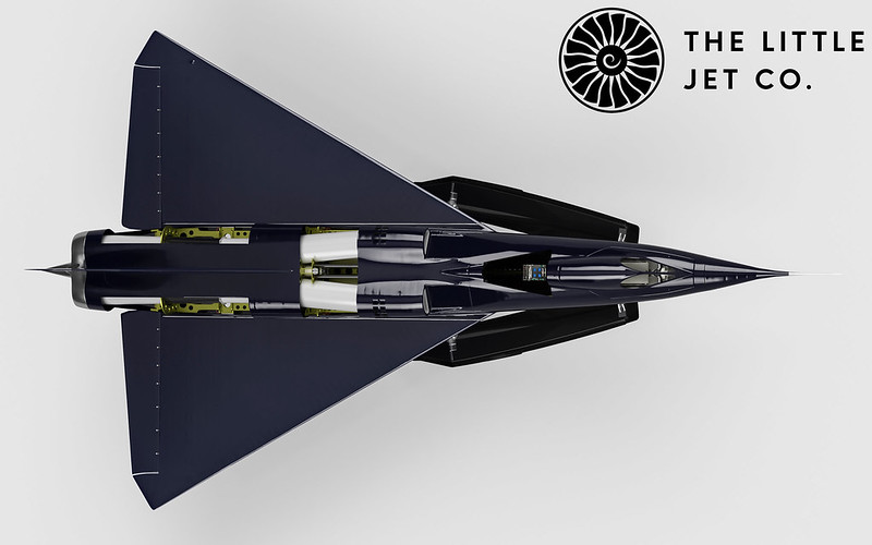
This measures 4.5 meters (14’ 9⅛) long with a span of 2.5 meters (8’ 2⅜), powered by two JCP300RXG turbines. Designed to operate solely from water!
TLJC
This measures 4.5 meters (14’ 9⅛) long with a span of 2.5 meters (8’ 2⅜), powered by two JCP300RXG turbines. Designed to operate solely from water!
TLJC
09-21-2017, 01:43 AM
#230
Mate your CAD drawings are next level!!
09-26-2017, 10:49 PM
#231
Thread Starter
Thanks Paul,
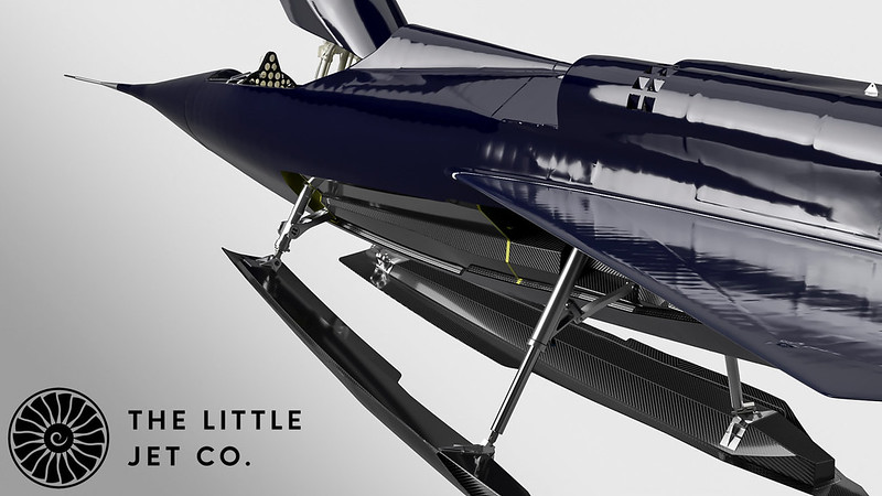
The ski mechanisms are manufactured from a mixture of Titanium (TI-6Al-4V), Stainless Steel (SS316L) and Aluminium (6082-T6/7075-T6) The skis are shown here with the oleo fully extended in the final take off position. The Skis have been the most challenging part of the project so far!
 <script async src="//embedr.flickr.com/assets/client-code.js" charset="utf-8"></script>
The ski mechanisms are manufactured from a mixture of Titanium (TI-6Al-4V), Stainless Steel (SS316L) and Aluminium (6082-T6/7075-T6) The skis are shown here with the oleo fully extended in the final take off position. The Skis have been the most challenging part of the project so far!
<script async src="//embedr.flickr.com/assets/client-code.js" charset="utf-8"></script>
 09-27-2017, 04:16 AM
#233
Thread Starter
Hi Ziv,
Thanks,
I'm nervous to put a date on it as the project has been delayed substantially along with some of my other projects because of several bereavements. I'm only just getting back on top of things. I'm pleased that this along with my other outstanding projects are moving along well now.
I think testing will be in February or March in either Spain or South Africa (With the appropriate aviation authorities agreement.)
Cheers,
Alex
11-21-2017, 11:46 PM
#234
Thread Starter
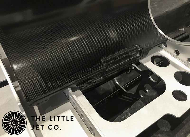
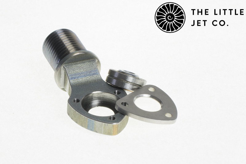
Finally we can start to get back to this thread. A quick shot of some of the parts being test fitted before all the internal structure goes to paint. This picture shows the left hand side inner carbon turbine bypass component. The intakes are water tight alone their entire length. You can see the seal and o-ring recesses built into the components.
 <script async src="//embedr.flickr.com/assets/client-code.js" charset="utf-8"></script>
<script async src="//embedr.flickr.com/assets/client-code.js" charset="utf-8"></script>
 11-22-2017, 01:03 PM
#237
My Feedback: (21)
Alex, absolutely just amazing, keep up the great work, the project from a build and design prospective is miles above anything that is currently is existence in the RC model world.
Keep the pictures coming and may the rest of the build go without issue.
Robert
Keep the pictures coming and may the rest of the build go without issue.
Robert
11-23-2017, 09:22 AM
#238
Thread Starter
Thanks for the comments guys.
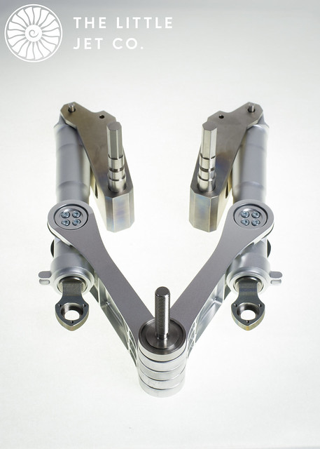
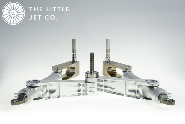
Here are some manufactured components starting with the forward ski mechanism. This has been manufactured from Titanium (TI-6Al-4V), Stainless Steel (SS316L) and Aluminium (6082-T6/7075-T6). The darker alloy is the TI with the bottom pivot made from SS the rest is T6.
I'm really please that everything fitted together perfectly with zero slop yet very free movement.
 <script async src="//embedr.flickr.com/assets/client-code.js" charset="utf-8"></script>
 <script async src="//embedr.flickr.com/assets/client-code.js" charset="utf-8"></script>
 <script async src="//embedr.flickr.com/assets/client-code.js" charset="utf-8"></script>
Here are some manufactured components starting with the forward ski mechanism. This has been manufactured from Titanium (TI-6Al-4V), Stainless Steel (SS316L) and Aluminium (6082-T6/7075-T6). The darker alloy is the TI with the bottom pivot made from SS the rest is T6.
I'm really please that everything fitted together perfectly with zero slop yet very free movement.
<script async src="//embedr.flickr.com/assets/client-code.js" charset="utf-8"></script><script async src="//embedr.flickr.com/assets/client-code.js" charset="utf-8"></script><script async src="//embedr.flickr.com/assets/client-code.js" charset="utf-8"></script>
11-25-2017, 04:12 AM
#241
Thread Starter
Thanks guys, it has certainly been a journey but the end is near...
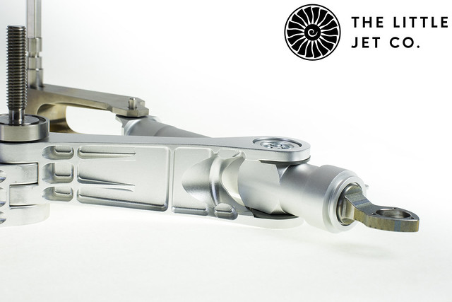
A bit more detail fro the front ski mechanism in the form of the spherical bearing housing which is used to attach the front oleo to the Ski. The housing is machined TI and SS cover.
 <script async src="//embedr.flickr.com/assets/client-code.js" charset="utf-8"></script>
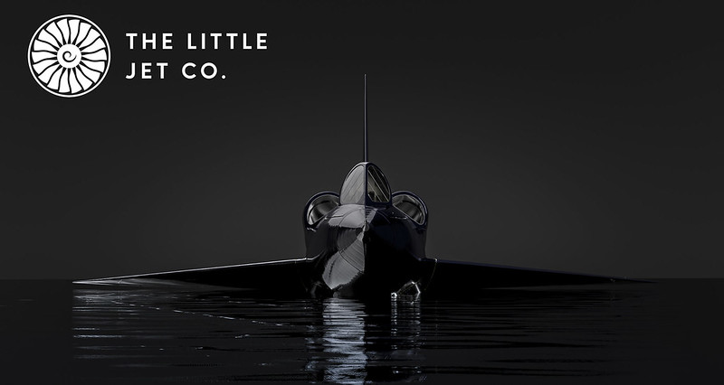
We hope to launch our website in the new year so I have been busy creating the imagery for the site. This is a render of our SeaDart CAD which will be used on one of the website sections.
 <script async src="//embedr.flickr.com/assets/client-code.js" charset="utf-8"></script>
A bit more detail fro the front ski mechanism in the form of the spherical bearing housing which is used to attach the front oleo to the Ski. The housing is machined TI and SS cover.
<script async src="//embedr.flickr.com/assets/client-code.js" charset="utf-8"></script>We hope to launch our website in the new year so I have been busy creating the imagery for the site. This is a render of our SeaDart CAD which will be used on one of the website sections.
<script async src="//embedr.flickr.com/assets/client-code.js" charset="utf-8"></script>
11-25-2017, 03:45 PM
#242
Slightly impressive Alex 
The ski mechanism in post #238 looks almost perfectly made.
Can you tell us a little about the manufacturing process..
How do you go from cad drawings to having something you can hold?
Is there a local machine shop that you use ? I would have thought the price for a one off like this would be prohibitive (it looks really well made and expensive)?
Paul.
11-26-2017, 01:58 AM
#243
Join Date: Jan 2007
Location: farnborough, , UNITED KINGDOM
Posts: 3,294
Likes: 0
Received 1 Like
on
1 Post
Paul I think you will find this level of model engineering is not for the average modellers wallet, this jet is at the F1 level in terms of materials, process and funding.
Turning CAD drawings into 'real' product is normally fairly straightforward, the CAD files can be loaded into a machine, a CNC or similar that converts this data back to the design and literally carves or 'prints' the part depending on the process, the CAD design is where the hours of time are spent ensuring the designed part is exactly as it needs to be.
Alex and the team I'm sure will chime in here but this it 'extreme engineering' at its best.
marcs
11-26-2017, 11:25 PM
#244
Thread Starter
Hi Paul, thanks Marc.
With all our bespoke projects and current commercial developments we start by scanning the entire aircraft. We specifically scanned the ski and retraction mechanisms on the SeaDart which also gave us confidence that our pattern was accurate.
From this data we can then reverse engineer the scanned elements and draw the CAD models with reference to mesh data, drawings and photos. The model then goes through a series of tests, any areas that are under stress are run through simulations which then determines material types, suitability etc…
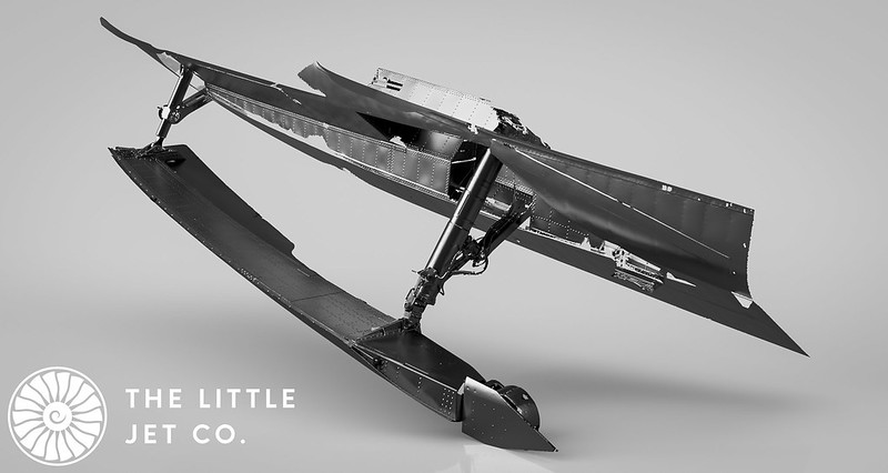
The below image is a render of the raw scan data from the SeaDart on display at Lakeland Florida. The aircraft we are building (BuNo135762) is slightly different to this example but the geometry of the gear is the same which is the primary reason we scanned it. The rear mechanism is a challenge and the scan helped us develop the mechanism on the model.
 <script async src="//embedr.flickr.com/assets/client-code.js" charset="utf-8"></script>
The CAD model has hundreds of separate components and all have been designed with manufacture in mind. While designing the machined components you have to have an understanding of the capabilities of the manufacturer and working with their engineers you can design a component that can be successfully machined. Building a scale model adds another level of complexity as we are now designing features that have no function other than to look the same as the original, it is in many of these areas where the expense comes.
All the machined components for the SeaDart undercarriage are tolerance fits so before we can send any data to the manufacture we have to make detailed drawings of each component. It is in these drawings that all the tolerances are specified. The tighter the tolerance the greater the expense. Each machined component then goes through a detailed inspection. Any out of tolerance areas are highighted and we can then decide to either accept the part of have it remade.
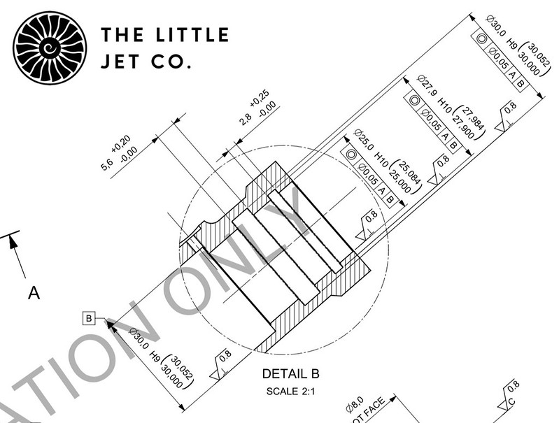
An example of one of our drawings detailing tolerances and surface finish requirements. You can see some of the tolerances in this example with the smallest at 52 microns.
 <script async src="//embedr.flickr.com/assets/client-code.js" charset="utf-8"></script>
As Marc suggested it’s all in the design which is around 90% of the process.
With all our bespoke projects and current commercial developments we start by scanning the entire aircraft. We specifically scanned the ski and retraction mechanisms on the SeaDart which also gave us confidence that our pattern was accurate.
From this data we can then reverse engineer the scanned elements and draw the CAD models with reference to mesh data, drawings and photos. The model then goes through a series of tests, any areas that are under stress are run through simulations which then determines material types, suitability etc…
The below image is a render of the raw scan data from the SeaDart on display at Lakeland Florida. The aircraft we are building (BuNo135762) is slightly different to this example but the geometry of the gear is the same which is the primary reason we scanned it. The rear mechanism is a challenge and the scan helped us develop the mechanism on the model.
<script async src="//embedr.flickr.com/assets/client-code.js" charset="utf-8"></script>The CAD model has hundreds of separate components and all have been designed with manufacture in mind. While designing the machined components you have to have an understanding of the capabilities of the manufacturer and working with their engineers you can design a component that can be successfully machined. Building a scale model adds another level of complexity as we are now designing features that have no function other than to look the same as the original, it is in many of these areas where the expense comes.
All the machined components for the SeaDart undercarriage are tolerance fits so before we can send any data to the manufacture we have to make detailed drawings of each component. It is in these drawings that all the tolerances are specified. The tighter the tolerance the greater the expense. Each machined component then goes through a detailed inspection. Any out of tolerance areas are highighted and we can then decide to either accept the part of have it remade.
An example of one of our drawings detailing tolerances and surface finish requirements. You can see some of the tolerances in this example with the smallest at 52 microns.
<script async src="//embedr.flickr.com/assets/client-code.js" charset="utf-8"></script>As Marc suggested it’s all in the design which is around 90% of the process.
11-27-2017, 12:39 AM
#245

Join Date: Nov 2003
Location: Curitiba, Parana, BRAZIL
Posts: 4,289
Likes: 0
Received 14 Likes
on
11 Posts
As far as I know , the most expensive hobby rc jet ever was Vitaly`s yak at the jet world masters. guess that this one is getting near the yak`s price tag!
stupendous work Alex.
stupendous work Alex.
11-27-2017, 01:11 AM
#246
Thanks for the detailed reply Alex.
I wish you all the best with the rest of the project, and look forward to some more pics!!
I wish you all the best with the rest of the project, and look forward to some more pics!!
11-27-2017, 02:34 AM
#247
Thread Starter
Thank guys,
The client has specified this level of detail and that does invetably have a cost associated with it. We have been fortunate that many of the companies involved have done a percentage of work free of charge and given substantial discounts in other areas. This is a project that has a lot of interest outside of the modelling world and without the enthusiasm of all involved it would not be possible to build a model that is engineered in this way.
For TLJC this is a technological demonstrator to show what we can achieve while developing techniques to produce a series of Hyper Scale Jet Kits at a price point that we are all used to. All the processes you see here are currently being used in our kit development which I'll be able to share with you all in the New Year.
 11-27-2017, 03:47 PM
#249

Thank guys,
The client has specified this level of detail and that does invetably have a cost associated with it. We have been fortunate that many of the companies involved have done a percentage of work free of charge and given substantial discounts in other areas. This is a project that has a lot of interest outside of the modelling world and without the enthusiasm of all involved it would not be possible to build a model that is engineered in this way.
For TLJC this is a technological demonstrator to show what we can achieve while developing techniques to produce a series of Hyper Scale Jet Kits at a price point that we are all used to. All the processes you see here are currently being used in our kit development which I'll be able to share with you all in the New Year.
The client has specified this level of detail and that does invetably have a cost associated with it. We have been fortunate that many of the companies involved have done a percentage of work free of charge and given substantial discounts in other areas. This is a project that has a lot of interest outside of the modelling world and without the enthusiasm of all involved it would not be possible to build a model that is engineered in this way.
For TLJC this is a technological demonstrator to show what we can achieve while developing techniques to produce a series of Hyper Scale Jet Kits at a price point that we are all used to. All the processes you see here are currently being used in our kit development which I'll be able to share with you all in the New Year.
with which jets Alex? Btw phenomenal work!
11-27-2017, 10:37 PM
#250
Thread Starter
Thanks, I'll have to start another thread on that.
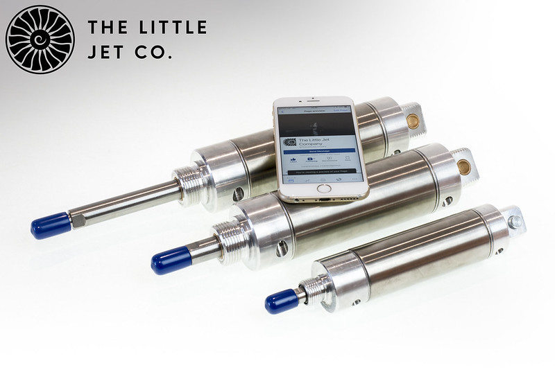
We looked closely at using hydraulics but the size of the model allowed us to use large pneumatic actuators producing plenty of force. The skis are nearly 5ft long so plenty of power is required.
Custom made pneumatic actuators... The large actuator at 80psi can produce a force on extension of 114kgs (251lbs) and a retraction force of 102Kgs (226lbs). The small forward actuator produces 64Kgs (141lbs) and 58kgs (129lbs).
 <script async src="//embedr.flickr.com/assets/client-code.js" charset="utf-8"></script>
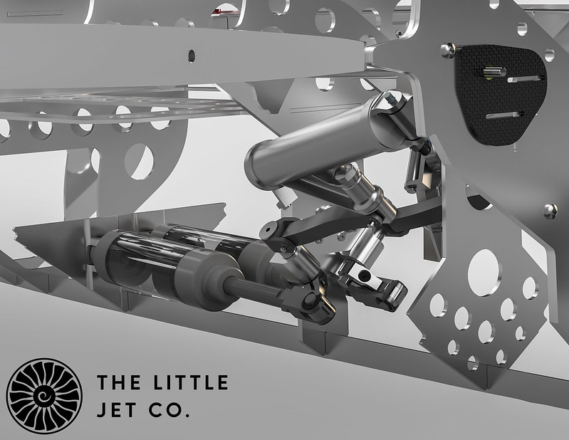
This is where they sit although there have been design changes to beef up the mounts and surrounding structure since I rendered this the actuator position hasn't changed.
 <script async src="//embedr.flickr.com/assets/client-code.js" charset="utf-8"></script>
We looked closely at using hydraulics but the size of the model allowed us to use large pneumatic actuators producing plenty of force. The skis are nearly 5ft long so plenty of power is required.
Custom made pneumatic actuators... The large actuator at 80psi can produce a force on extension of 114kgs (251lbs) and a retraction force of 102Kgs (226lbs). The small forward actuator produces 64Kgs (141lbs) and 58kgs (129lbs).
<script async src="//embedr.flickr.com/assets/client-code.js" charset="utf-8"></script>This is where they sit although there have been design changes to beef up the mounts and surrounding structure since I rendered this the actuator position hasn't changed.
<script async src="//embedr.flickr.com/assets/client-code.js" charset="utf-8"></script>