


US NAVY SeaDart F2Y (Flying boat) Build

 10-16-2015, 08:44 AM
#52

Thread Starter

Thanks guys.
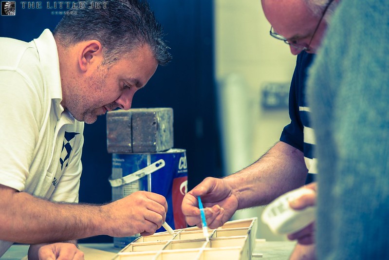
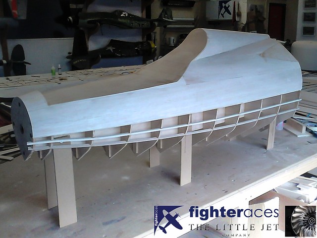
One half of the center section built in the same manner as the wing panels.
 <script async src="//embedr.flickr.com/assets/client-code.js" charset="utf-8"></script>
 <script async src="//embedr.flickr.com/assets/client-code.js" charset="utf-8"></script>
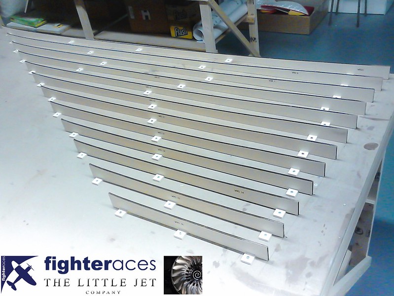
Jigs built onto the work surface to reverse the panel and sheet the underside.
 <script async src="//embedr.flickr.com/assets/client-code.js" charset="utf-8"></script>
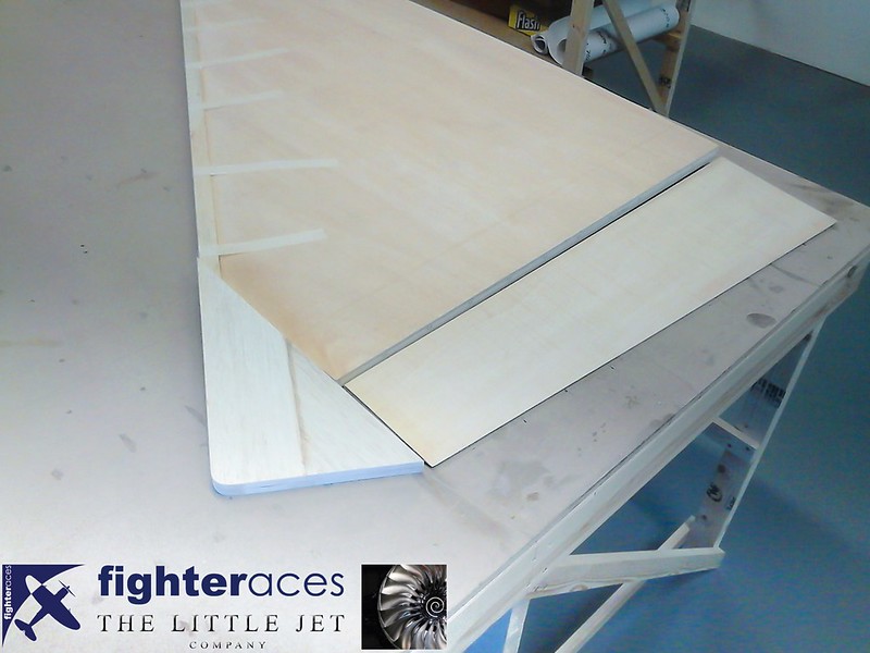
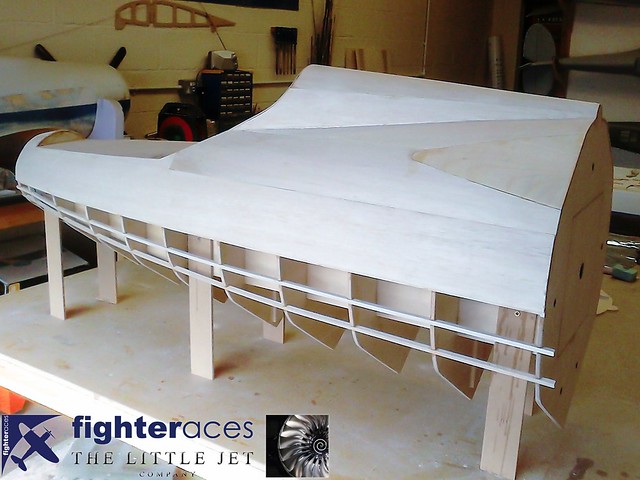
The wing starting to take shape.
 <script async src="//embedr.flickr.com/assets/client-code.js" charset="utf-8"></script>
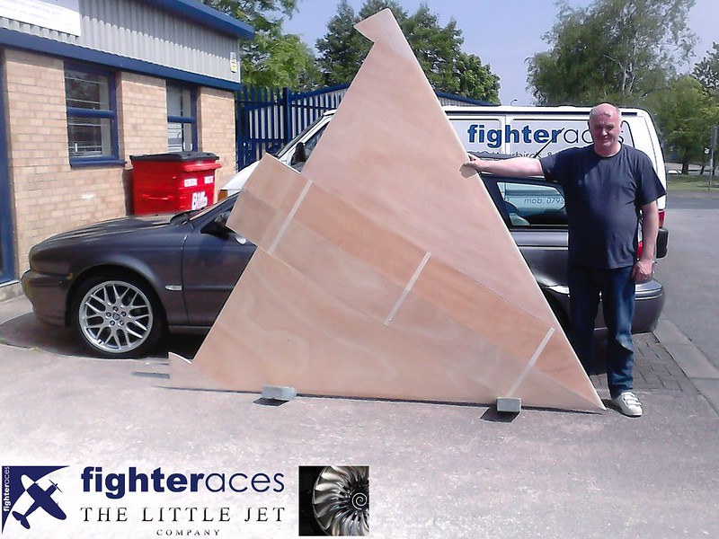
John from the team at Fighteraces rightly pleased with the results so far. Fin, wings, elevons and center sections now complete ready for surface preperation so its onto the fuselage.
 <script async src="//embedr.flickr.com/assets/client-code.js" charset="utf-8"></script>
One half of the center section built in the same manner as the wing panels.
<script async src="//embedr.flickr.com/assets/client-code.js" charset="utf-8"></script><script async src="//embedr.flickr.com/assets/client-code.js" charset="utf-8"></script>Jigs built onto the work surface to reverse the panel and sheet the underside.
<script async src="//embedr.flickr.com/assets/client-code.js" charset="utf-8"></script>The wing starting to take shape.
<script async src="//embedr.flickr.com/assets/client-code.js" charset="utf-8"></script>John from the team at Fighteraces rightly pleased with the results so far. Fin, wings, elevons and center sections now complete ready for surface preperation so its onto the fuselage.
<script async src="//embedr.flickr.com/assets/client-code.js" charset="utf-8"></script>
 10-16-2015, 01:16 PM
#54
Thread Starter
They certainly are 
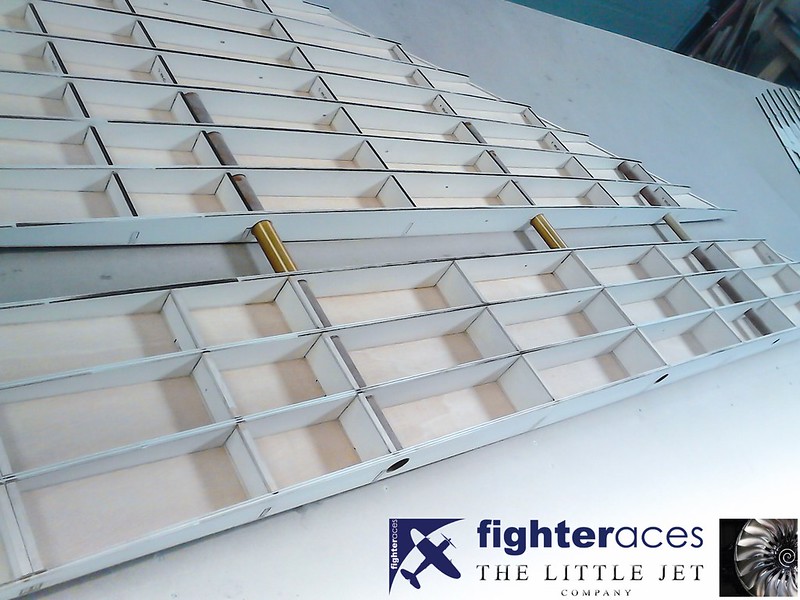
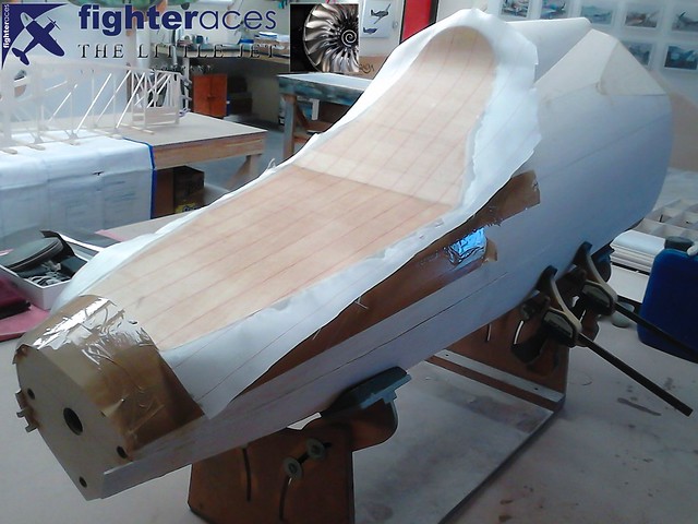
"The first picture shows the three Petrausch Modellbau wing tubes nicely plus the balsa capped shear spars in the centre section. Note the balsa caps still to be added to the outer panel.
The jigs are simply mirror images of the ribs but with the 2mm skins taken into account so once skinned on top and flipped over, the panel is a perfect fit in the jig ready for the underside to be skinned.
With the underside skinned, the elevon is removed. The TE of the 2mm skins is chamfered down to a feather edge and 0.3mm Proskin is laminated in between the 2 to give a stiff but sharp TE to the elevon. The hard balsa tip block has 1/32" ply sandwiched between two 1/2" balsa sheets as does the LE block to ensure the LE retains a nice hard edge to it's radius.
The final shot with John shows the wings fully glassed. Quite a job in itself given it's 35 sq ft area so a combined 70 sq ft top & bottom. Glassing was done as per the fin with Fighterace's own L285 resin & a close weave 125g cloth + peel ply."
Phil Clark, Fighteraces
 10-18-2015, 04:09 AM
#57

Join Date: Nov 2003
Location: Curitiba, Parana, BRAZIL
Posts: 4,289
Likes: 0
Received 14 Likes
on
11 Posts
It would be a nice new speed record!! go for it! LOL
Anyway this sea dart project is amazing... looking forward for the builfding and without doubt many nice flights. And there is any chance to fly it from dry land? If my memory doesn fail me this plane had some sort of small wheels attached to it in the skis
Anyway this sea dart project is amazing... looking forward for the builfding and without doubt many nice flights. And there is any chance to fly it from dry land? If my memory doesn fail me this plane had some sort of small wheels attached to it in the skis
10-18-2015, 10:43 AM
#58
Thread Starter
Thanks...
The SeaDart we are modelling didn't have a wheel at the back of the skis but used a large dolly although I think on the second SeaDart we build we will incorporate the wheel at the rear of the ski. The full size only used it for ingress/egress from the water on a shallow slipway. I'm not sure how the model would cope with a takeoff from land in its waterborne configuration. its a beast of a model and weighing over 60kg its a lot of stress on the back of those skis...
Here's a picture of the wheels on the full size, they rotated flat once in the water.
 <script async src="//embedr.flickr.com/assets/client-code.js" charset="utf-8"></script>
The SeaDart we are modelling didn't have a wheel at the back of the skis but used a large dolly although I think on the second SeaDart we build we will incorporate the wheel at the rear of the ski. The full size only used it for ingress/egress from the water on a shallow slipway. I'm not sure how the model would cope with a takeoff from land in its waterborne configuration. its a beast of a model and weighing over 60kg its a lot of stress on the back of those skis...
Here's a picture of the wheels on the full size, they rotated flat once in the water.
<script async src="//embedr.flickr.com/assets/client-code.js" charset="utf-8"></script>
10-18-2015, 03:23 PM
#59
Join Date: Nov 2003
Location: Curitiba, Parana, BRAZIL
Posts: 4,289
Likes: 0
Received 14 Likes
on
11 Posts
Awesome! And absolutely, using the wheels would be a lot more practical than using a dolly,, and maybe after trying some taxiing in the second prototype , if the model handles well on ground it would be worth to give a shot and try a dry takeoff and landing.
Just found a small EDF model from Japan.. even at this scale it flies and lands pretty much effortless. What a nice plane.
https://www.youtube.com/watch?v=aiMBPUXz78U
Just found a small EDF model from Japan.. even at this scale it flies and lands pretty much effortless. What a nice plane.
https://www.youtube.com/watch?v=aiMBPUXz78U
10-18-2015, 10:12 PM
#60
Thread Starter
Yeah... he did well with that EDF hopefully ours will be as easy to operate off water. Here's a video of that model once he had mastered it. Looks to go well...
https://www.youtube.com/watch?v=yLDU5K32-po
https://www.youtube.com/watch?v=yLDU5K32-po
10-18-2015, 11:29 PM
#61
Senior Member
Join Date: Sep 2015
Posts: 118
Likes: 0
Received 0 Likes
on
0 Posts
Alex
Excellent Project. You must have a client with very deep pockets !
I was wondering who is going to be on the sticks for the maiden flight. Might Ali come back to the UK for such a task !?
Excellent Project. You must have a client with very deep pockets !
I was wondering who is going to be on the sticks for the maiden flight. Might Ali come back to the UK for such a task !?
10-19-2015, 01:22 AM
#62
Thread Starter
Hi, This project is certainly on the crazy side which is probably why I like it so much
Its not a UK based model so all the SeaDarts will be shipped out of the EU on completion. Only initial water taxi tests will be carried out in the UK although this may change but at this stage all flying will be at a large private estate abroad. We are looking into all the legal bits and pieces at the moment in regard to flying the model... Initial flights are likely to be a good year away yet. I hope to start the taxi tests in the summer. I'm really looking forward to driving a very expensive twin turbine boat around I'm not sure I'm looking forward to the test flights as much though!
The model will be flown by the client who is a very competent jet pilot, I believe his intention is to do all the testing himself and he is more than capable on this front.
Cheers, Alex
Its not a UK based model so all the SeaDarts will be shipped out of the EU on completion. Only initial water taxi tests will be carried out in the UK although this may change but at this stage all flying will be at a large private estate abroad. We are looking into all the legal bits and pieces at the moment in regard to flying the model... Initial flights are likely to be a good year away yet. I hope to start the taxi tests in the summer. I'm really looking forward to driving a very expensive twin turbine boat around
I'm not sure I'm looking forward to the test flights as much though! The model will be flown by the client who is a very competent jet pilot, I believe his intention is to do all the testing himself and he is more than capable on this front.
Cheers, Alex
10-22-2015, 03:38 AM
#64
Thread Starter
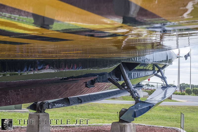
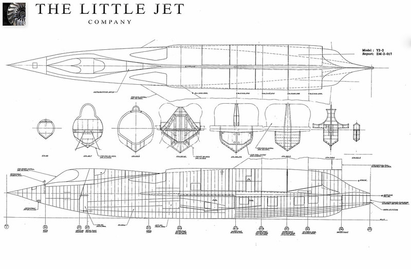
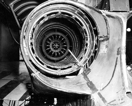
This fuselage presents a particular challenge to the team as our only accurate drawing shows two elevations with eight cross sections spread over a four meter model. Lots of information can be extracted from the drawing but the last quarter is completely different as the aircraft we are modelling has the after burning engines and this drawing shows the very first SeaDart with the J34 non after burning engines. As a result the top rear section of the aircraft is very different.
 <script async src="//embedr.flickr.com/assets/client-code.js" charset="utf-8"></script>
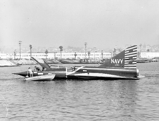
This photo shows the difference when looking at the aircraft with afterburning J46 engines.
 <script async src="//embedr.flickr.com/assets/client-code.js" charset=“utf-8"></script>
Fighteraces have a big task filling in the holes using our photographic research and some of the other drawing research to accurately re-create the second SeaDart built (YF2Y-1). The hull has been drawn in CAD using measurements from the Florida SeaDart to facilitate the creation of accurate former sections. The ski retraction mechanism is very sensitive geometrically so its critical the hull is built in accordance with the CAD work or the ski’s will not retract correctly into the ski wells.
 <script async src="//embedr.flickr.com/assets/client-code.js" charset="utf-8"></script>
<script async src="//embedr.flickr.com/assets/client-code.js" charset="utf-8"></script>This photo shows the difference when looking at the aircraft with afterburning J46 engines.
<script async src="//embedr.flickr.com/assets/client-code.js" charset=“utf-8"></script>Fighteraces have a big task filling in the holes using our photographic research and some of the other drawing research to accurately re-create the second SeaDart built (YF2Y-1). The hull has been drawn in CAD using measurements from the Florida SeaDart to facilitate the creation of accurate former sections. The ski retraction mechanism is very sensitive geometrically so its critical the hull is built in accordance with the CAD work or the ski’s will not retract correctly into the ski wells.
<script async src="//embedr.flickr.com/assets/client-code.js" charset="utf-8"></script>
Last edited by Alex48; 10-22-2015 at 03:41 AM.
10-22-2015, 12:45 PM
#65
Thread Starter
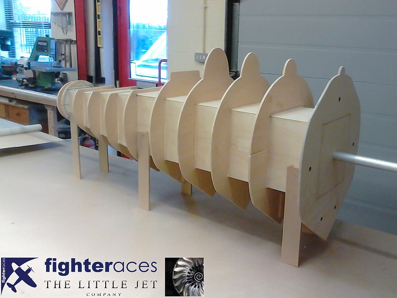
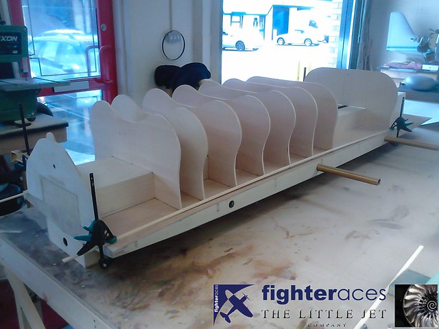
Of the 11 formers shown here, only 3 were shown on our drawings, so the remaining 8 had to be produced taking what information we could from the drawings + refering to the multitude of photos. We opted to break the fuselage at a prominent panel line a little ahead of the intakes + the formers spacing shown is approx. 4" which will give excellent support for the skin especially when a higher density than may be normal for a 'flying' model of 1/4" sq stringers are added as well.
There was nothing 'Hi Tech' about the production of the 8 new formers........good old paper & pencil & some old fashioned drafting techniques was all that was required (A set of French Curves were worth their weight in gold!!). To ensure the whole nose section remained true, it was built around an 8" square 1/8" ply box (which tapers off towards the nose). This in turn has a 1" aluminium tube running through it that can be supported at either end to facilitate easy 'finishing' of the nose when it comes round to glassing, surface prep & painting.
You can see a series of 5 holes on the rear face......these are 10mm I/D phenolic tubes that will take shorts 10mm aluminium alignment pins......the front former of the main rear fuselage will obviously have corresponding phenolic's to ensure perfect alignment of the 2 sections.
Phil Clark, FighterAces
10-23-2015, 02:00 AM
#67
Thread Starter
They're doing well thats for sure! The finished pattern will be awesome... only seven or eight weeks to wait
With three guys working full time and sometimes six days a week means progress is fairly swift. It may also look fast at the moment as I catch up with the photos. I'll update the thread daily but it will go quiet in mid December for a month then back full time in the New Year where we'll be onto the scanning, tooling and composite work.
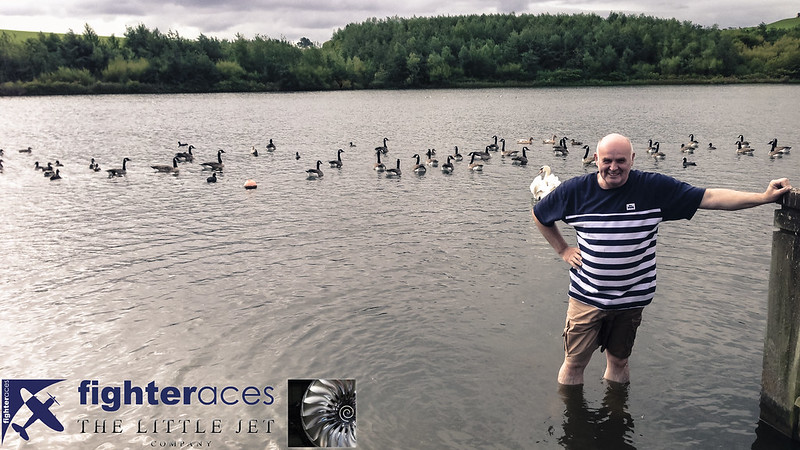
On my last visit to FighterAces we wanted to find somewhere close to the workshop to do the initial buoyancy tests. John seemed delighted to be volunteered to test the slipway out in a lake at Herrington Park or at least he was until he slipped! Its a good spot to just test the buoyancy against our calculations but I think we would probably get arrested if we tested the working model here not to mention multiple duck strikes! We'll hire a water sport lake here in Cambridgeshire for the taxi tests...
 <script async src="//embedr.flickr.com/assets/client-code.js" charset="utf-8"></script>
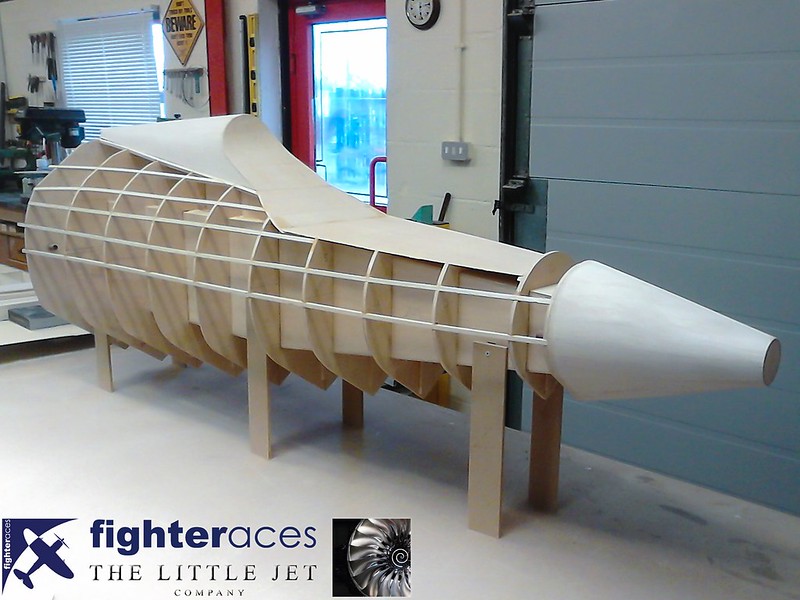
Some stringers fitted and the start of the sheeting for the forward fuselage.
 <script async src="//embedr.flickr.com/assets/client-code.js" charset="utf-8"></script>
With three guys working full time and sometimes six days a week means progress is fairly swift. It may also look fast at the moment as I catch up with the photos. I'll update the thread daily but it will go quiet in mid December for a month then back full time in the New Year where we'll be onto the scanning, tooling and composite work.
On my last visit to FighterAces we wanted to find somewhere close to the workshop to do the initial buoyancy tests. John seemed delighted to be volunteered to test the slipway out in a lake at Herrington Park or at least he was until he slipped! Its a good spot to just test the buoyancy against our calculations but I think we would probably get arrested if we tested the working model here
not to mention multiple duck strikes! We'll hire a water sport lake here in Cambridgeshire for the taxi tests... <script async src="//embedr.flickr.com/assets/client-code.js" charset="utf-8"></script>Some stringers fitted and the start of the sheeting for the forward fuselage.
<script async src="//embedr.flickr.com/assets/client-code.js" charset="utf-8"></script>
Last edited by Alex48; 10-23-2015 at 02:54 AM.
10-24-2015, 03:26 AM
#68
Thread Starter
I mentioned buoyancy in the previous post and its probably worth explaining why this needs to be tested. From the very first meeting with the client I expressed a concern as to how heavy we need to make the model so it sits at the correct waterline. To have it bobbing on the water like a bath toy just isn't acceptable. We are going to great lengths to assure scale fidelity and the sit of any model either on the ground or in the water is very important to the overall look and ultimately is part of the identity of that aircraft. We know from our research the exact waterline required which sits 0.46 meters (18 inches) below the root leading edge and flush with the back of the wing.
 <script async src="//embedr.flickr.com/assets/client-code.js" charset="utf-8"></script>
We talked at length with Fighteraces about possible solutions and collectively came up with this basic plan.
With the basic principle that one liter of water is equal to one kilo in weight we can cut the hull along the scale water line to find the volume that we need to displace. This varies slightly with fuel state but not significantly. Having designed the hull in CAD while doing the ski retraction work we could easily cut across the water line and work out the volume. Assuming we make the Ski’s neutrally buoyant we need to displace 89 litres of water, hence the model needs to weigh 89kg (196lbs). We’d like the model to weigh 60kg (132lbs) as this gives an acceptable wing loading, any more and its starting to become a handful especially with our scale aerofoil sections. The reason for having the available thrust equal to weight is that scale models don't have the energy of their full size counterparts. With excessive power we can create the impression of energy using the thrust intelligently which allows us to fly the model in a scale manner.
We are now left with a model weighing 29kgs (63lbs) more than we would like. The solution with the obvious requirement for lots of tests is to build a 29 litre wet compartment into the hull. This would be shaped to distribute the water with regard to the CG. The tank would flood once the aircraft is sitting on the water and have several large openings concealed in the formers that the front and rear ski mechanisms will be mounted to. Its easy getting the water in but we now need to evacuate it during the takeoff.
Believe it or not the full size actually took on water, in one instance the ground crew forgot to remove the stoppers in the vents and the aircraft took off with over 1000kgs of water in the hull. The difference being is that the water wasn't wanted in the case of the full size but just accumulated from the open areas at the back near the jet nozzles.
 <script async src="//embedr.flickr.com/assets/client-code.js" charset="utf-8"></script>
Conveniently the SeaDart has a large water rudder at the back which doubles as a speed brake. The area available to evacuate the water from is large when the water rudders are cracked open so the hope is by the time the model has de-planed its skis the compartments water level should be in line with the current waterline of the model. We have lots of other ideas but this is by far the simplest so starting here seems the best choice, if this doesn't work we will move to the more complex solutions…
The initial plan is to float the pattern once finished bearing in mind we have to add 14kgs (31lbs) to take into account the lack of ski wells. So if we load the pattern to 103kgs (227lbs) with the correct CG then the waterline should be at the scale position.
<script async src="//embedr.flickr.com/assets/client-code.js" charset="utf-8"></script> We talked at length with Fighteraces about possible solutions and collectively came up with this basic plan.
With the basic principle that one liter of water is equal to one kilo in weight we can cut the hull along the scale water line to find the volume that we need to displace. This varies slightly with fuel state but not significantly. Having designed the hull in CAD while doing the ski retraction work we could easily cut across the water line and work out the volume. Assuming we make the Ski’s neutrally buoyant we need to displace 89 litres of water, hence the model needs to weigh 89kg (196lbs). We’d like the model to weigh 60kg (132lbs) as this gives an acceptable wing loading, any more and its starting to become a handful especially with our scale aerofoil sections. The reason for having the available thrust equal to weight is that scale models don't have the energy of their full size counterparts. With excessive power we can create the impression of energy using the thrust intelligently which allows us to fly the model in a scale manner.
We are now left with a model weighing 29kgs (63lbs) more than we would like. The solution with the obvious requirement for lots of tests is to build a 29 litre wet compartment into the hull. This would be shaped to distribute the water with regard to the CG. The tank would flood once the aircraft is sitting on the water and have several large openings concealed in the formers that the front and rear ski mechanisms will be mounted to. Its easy getting the water in but we now need to evacuate it during the takeoff.
Believe it or not the full size actually took on water, in one instance the ground crew forgot to remove the stoppers in the vents and the aircraft took off with over 1000kgs of water in the hull. The difference being is that the water wasn't wanted in the case of the full size but just accumulated from the open areas at the back near the jet nozzles.
<script async src="//embedr.flickr.com/assets/client-code.js" charset="utf-8"></script>Conveniently the SeaDart has a large water rudder at the back which doubles as a speed brake. The area available to evacuate the water from is large when the water rudders are cracked open so the hope is by the time the model has de-planed its skis the compartments water level should be in line with the current waterline of the model. We have lots of other ideas but this is by far the simplest so starting here seems the best choice, if this doesn't work we will move to the more complex solutions…
The initial plan is to float the pattern once finished bearing in mind we have to add 14kgs (31lbs) to take into account the lack of ski wells. So if we load the pattern to 103kgs (227lbs) with the correct CG then the waterline should be at the scale position.
Last edited by Alex48; 10-24-2015 at 06:33 AM.
10-24-2015, 10:37 AM
#69
Thread Starter
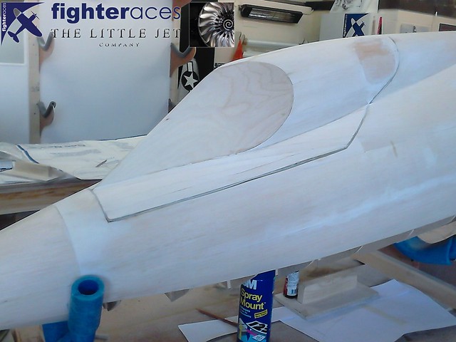
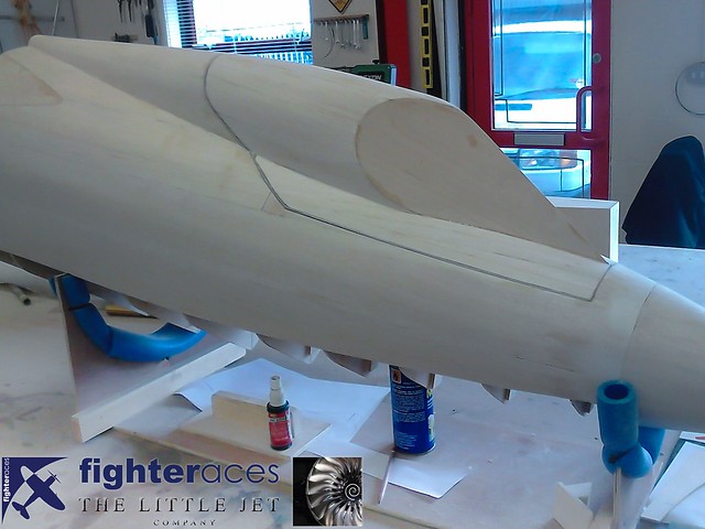
Some more sheeting complete on the forward fuselage section and a start has been made on the large canopy section. The canopy will be fully functional like the full size as you can see in the historical image on my previous post. Another 8 inch ply box has also been made for the aft fuselage formers to keep everything true.
 <script async src="//embedr.flickr.com/assets/client-code.js" charset="utf-8"></script>
 <script async src="//embedr.flickr.com/assets/client-code.js" charset="utf-8"></script>
 <script async src="//embedr.flickr.com/assets/client-code.js" charset="utf-8"></script>
<script async src="//embedr.flickr.com/assets/client-code.js" charset="utf-8"></script><script async src="//embedr.flickr.com/assets/client-code.js" charset="utf-8"></script><script async src="//embedr.flickr.com/assets/client-code.js" charset="utf-8"></script>
Last edited by Alex48; 10-24-2015 at 10:42 AM.
10-24-2015, 12:30 PM
#70

My Feedback: (6)
Alex
A bit more triva when we watched it take off after it cleared the water it had a stream of water trailing for about a 1/4 mile that then turned into what appeared to be a mist. In looking at the shape of the bay right after take off the pilot had to start a slight left turn to stay over water, and from what I remember he did an orbit around NAS North Island and back to the bay all other testing was done over water west of North Island, and south of point loma.
Boy has this thread jogged some old memories
Cheers Bob T hope you don't mind
10-25-2015, 08:07 AM
#72
Thread Starter
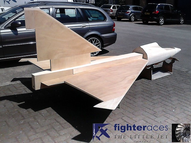
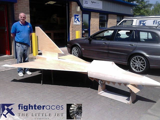
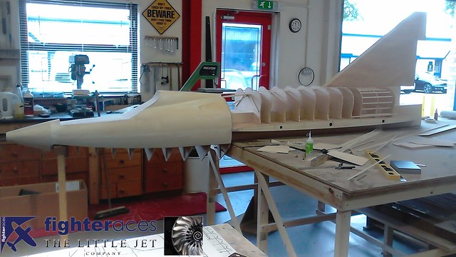
Out in the sunshine for a motivational assembly of whats been done. Some imagination required but I'm sure you get the idea... Its a shame the photos can't do the size much justice as in person it looks colossal. Fighteraces are doing an excellent job and proving that they are among the best around for this sort of thing. I'm looking forward to posting some progress next week!
 <script async src="//embedr.flickr.com/assets/client-code.js" charset="utf-8"></script>
 <script async src="//embedr.flickr.com/assets/client-code.js" charset="utf-8"></script>
<script async src="//embedr.flickr.com/assets/client-code.js" charset="utf-8"></script><script async src="//embedr.flickr.com/assets/client-code.js" charset="utf-8"></script>
10-26-2015, 03:29 PM
#73
Thread Starter
The canopy hatch built and glassed...
 <script async src="//embedr.flickr.com/assets/client-code.js" charset="utf-8"></script>
 <script async src="//embedr.flickr.com/assets/client-code.js" charset="utf-8"></script>
 <script async src="//embedr.flickr.com/assets/client-code.js" charset="utf-8"></script>
<script async src="//embedr.flickr.com/assets/client-code.js" charset="utf-8"></script><script async src="//embedr.flickr.com/assets/client-code.js" charset="utf-8"></script><script async src="//embedr.flickr.com/assets/client-code.js" charset="utf-8"></script>
10-28-2015, 07:16 AM
#74
Thread Starter
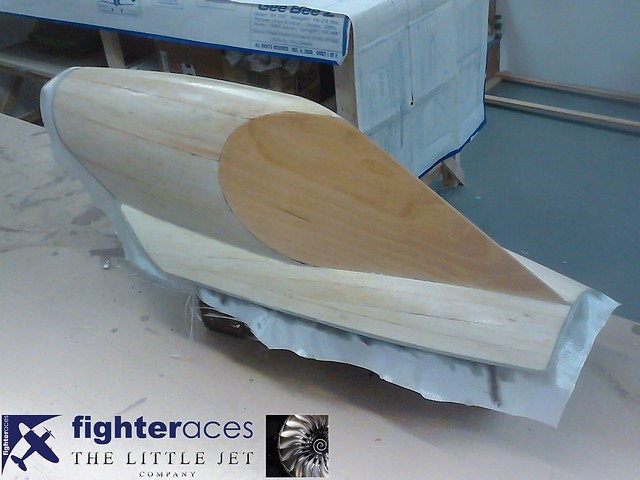
Work on the rear section. There was alot of time and effort put into getting those former shapes correct!
 <script async src="//embedr.flickr.com/assets/client-code.js" charset="utf-8"></script>
Its slowly starting to look a bit more like a SeaDart.
 <script async src="//embedr.flickr.com/assets/client-code.js" charset="utf-8"></script>
<script async src="//embedr.flickr.com/assets/client-code.js" charset="utf-8"></script>Its slowly starting to look a bit more like a SeaDart.
<script async src="//embedr.flickr.com/assets/client-code.js" charset="utf-8"></script>
Last edited by Alex48; 10-28-2015 at 09:49 AM.
