


US NAVY SeaDart F2Y (Flying boat) Build
 09-08-2015, 01:42 AM
#26

Thread Starter

Hi Dennis,
Yes the salt water was an issue as the engines had magnesium compressor casings. The inside walls would grow whiskers from the contamination until the compressor blades scraped the walls. They sprayed large amounts of fresh water into the idling engines and also particles of walnut shells to cleanse the casings. Fresh water was also sprayed into the the engines before shutdown on the ramp.
Before introducing the above procedure they experienced power losses of up to 40% due to salt contamination! I don't think the spray will be an issue for us but the model will have the auxiliary intakes so we could blank the main intakes for takeoff and open them once airborne. Extensive taxi tests will be needed to ascertain if it will cause us a problem although we are designing a solution, but in the quest to keep things simple we won't integrate it if we don't need it.

Last edited by Alex48; 09-08-2015 at 05:07 AM.
 09-08-2015, 06:10 PM
#27

My Feedback: (6)
Alex
some more trivia, from an old geezer
In you research package do you have any pic's of the ripple on San Diego bay ? the above pic is not what I remember, I stood on the old fisherman's wharf and the bay looked like about a 2 inch ripple, so as we watching the take off and from what I remember as the Dart came up on the ski's it was just a blur, and at lift off it became clear. the Coast Guard had closed off the area for the take off from all boats except the rescue and tow if needed.
cheers Bob T
09-10-2015, 12:07 AM
#28
Thread Starter
Hi Bob,
All the photos I have are mainly close ups from support boats or helicopters although there is some good footage showing what you describe in the film archives, I'll try and dig out a clip.
Cheers
All the photos I have are mainly close ups from support boats or helicopters although there is some good footage showing what you describe in the film archives, I'll try and dig out a clip.
Cheers
09-11-2015, 07:32 AM
#29
Thread Starter
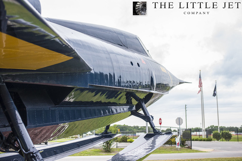
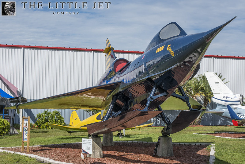
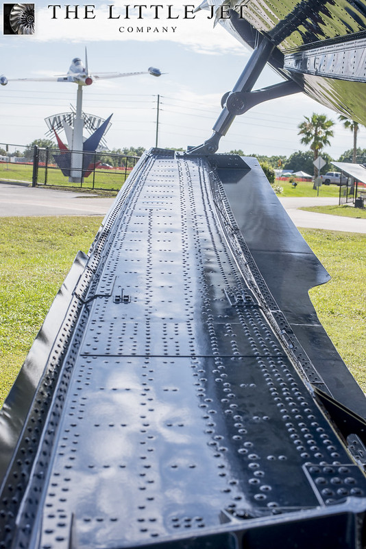
A few photos from hundreds of high resolution images taken on our research trip to Orlando at the SUN'nFUN museum at Lakeland Airport. The museum were helpful and gave us permission to get up close to the SeaDart. This SeaDart YF2Y-1, 135765 never flew but was finished to the specification developed in SeaDart three.
We spent two days photographing every inch of the aircraft, making templates and taking down measurements to complement the research already collected from San Diego.
This helped our understanding of the ski retraction mechanisms and also proved invaluable for the rivet counter that lurks within all scale modellers... over 100’000 to be applied to our 1/4 scale model. We were carful to cross reference this aircraft with our research which showed some differences mainly due to the passage of time. With these differences filtered out and our San Diego data merged we now had enough to make a start designing YF2Y-1, 135762.
 <script async src="//embedr.flickr.com/assets/client-code.js" charset="utf-8"></script>
 <script async src="//embedr.flickr.com/assets/client-code.js" charset="utf-8"></script>
 <script async src="//embedr.flickr.com/assets/client-code.js" charset="utf-8"></script>
We spent two days photographing every inch of the aircraft, making templates and taking down measurements to complement the research already collected from San Diego.
This helped our understanding of the ski retraction mechanisms and also proved invaluable for the rivet counter that lurks within all scale modellers... over 100’000 to be applied to our 1/4 scale model. We were carful to cross reference this aircraft with our research which showed some differences mainly due to the passage of time. With these differences filtered out and our San Diego data merged we now had enough to make a start designing YF2Y-1, 135762.
<script async src="//embedr.flickr.com/assets/client-code.js" charset="utf-8"></script><script async src="//embedr.flickr.com/assets/client-code.js" charset="utf-8"></script><script async src="//embedr.flickr.com/assets/client-code.js" charset="utf-8"></script>
Last edited by Alex48; 09-12-2015 at 01:37 AM.
09-15-2015, 05:10 AM
#31
Thread Starter
The research was complete enough to start making a decisions regarding our approach to the model.
Many scales were discussed and after weighing up all the options we enthusiastically went with 1/4 scale which makes the model over 4 meters (157 inches) in length and 2.5 meters (98 inches) in span.
Helped along with a suitable budget it was decided that the model’s scale fidelity be put before all other considerations. So everything from this point is done to achieve that goal regardless of the more traditional constraints to such a project. This is probably as far from a traditionally built model as one could get.
The models whole philosophy dictates a different approach to its creation. There are seven companies and hundreds of people involved in it’s design and fabrication. All the companies are based here in the UK which was important to us and range from small businesses to multi million pound engineering firms. Parts being built alongside orders for Aston Martin and the top Formula One teams is really exciting. Its been a real privilege meeting the various companies around the UK and to see people so excited and engaged with the project is heartening. Although they do often add they think we are completely insane... which I think is part of their attraction.
The further along we get the more confident I become at this projects eventual success but there is still a risk over and above a ground based scratch build. To discard this or not be honest with ones self would be foolish. With this in mind our approach to everything is with reproduction in mind.
Initially two models will be built, the first a pure prototype whereby we can try our design ideas with the second used for the implementation of the designed solution. Both models will be built concurrently with the obvious need for a slight offset in build stages.
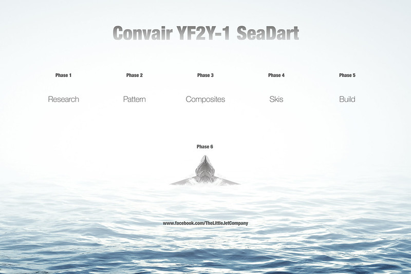
The project has been broken down in six distinct phases. Research, Pattern, Composites, Skis, Build and Testing.
 <script async src="//embedr.flickr.com/assets/client-code.js" charset="utf-8"></script>
Many scales were discussed and after weighing up all the options we enthusiastically went with 1/4 scale which makes the model over 4 meters (157 inches) in length and 2.5 meters (98 inches) in span.
Helped along with a suitable budget it was decided that the model’s scale fidelity be put before all other considerations. So everything from this point is done to achieve that goal regardless of the more traditional constraints to such a project. This is probably as far from a traditionally built model as one could get.
The models whole philosophy dictates a different approach to its creation. There are seven companies and hundreds of people involved in it’s design and fabrication. All the companies are based here in the UK which was important to us and range from small businesses to multi million pound engineering firms. Parts being built alongside orders for Aston Martin and the top Formula One teams is really exciting. Its been a real privilege meeting the various companies around the UK and to see people so excited and engaged with the project is heartening. Although they do often add they think we are completely insane... which I think is part of their attraction.
The further along we get the more confident I become at this projects eventual success but there is still a risk over and above a ground based scratch build. To discard this or not be honest with ones self would be foolish. With this in mind our approach to everything is with reproduction in mind.
Initially two models will be built, the first a pure prototype whereby we can try our design ideas with the second used for the implementation of the designed solution. Both models will be built concurrently with the obvious need for a slight offset in build stages.
The project has been broken down in six distinct phases. Research, Pattern, Composites, Skis, Build and Testing.
<script async src="//embedr.flickr.com/assets/client-code.js" charset="utf-8"></script>
Last edited by Alex48; 09-15-2015 at 05:18 AM.
09-24-2015, 07:31 AM
#33
Thread Starter
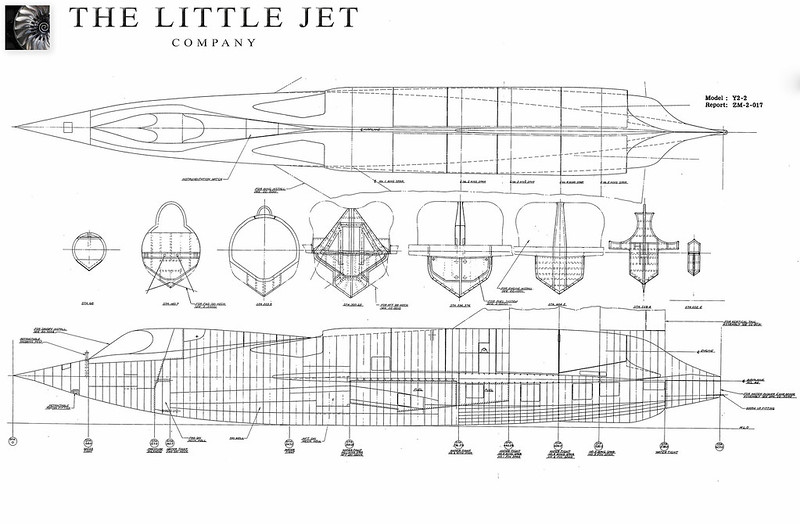
Although the budget allowed for a full CNC’d pattern we were keen that this model have as much of the character as the original. Often very large models are impressive only due to their size but lack any real depth of character. By involving professional modellers in the production of the pattern we can build in the modellers touch, add every rivet (over 100,000), every panel line and every bowed or warped panel to create something very believable. This is all possible straight from CAD but felt we could better achieve the desired character of the aircraft by doing the detail manually, after all... the original was built by hand so we felt it would be fitting that the pattern is also built in this way.
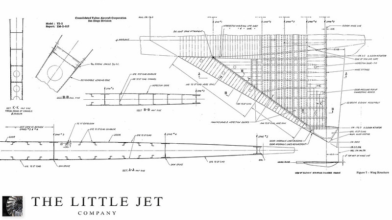
This decision was helped along with the fact that we still had some holes in the research and areas of the model would need to be done with reference to photos alone, we believed an experienced team of professional modellers would have more success with this approach and have a sound understanding of whats required in a large complex model such as this. The SeaDart pattern is built purely by hand using scaled original drawings taken from the Convair Archives. All drawings were painstakingly digitally cleaned then enlarged to exactly 1/4 scale giving very good resolution and a decent start for making the pattern.
 <script async src="//embedr.flickr.com/assets/client-code.js" charset="utf-8"></script>
Our other custom composite jet projects will involve both CNC’d patterns and hand crafted external detail which offers a good solution for the manufacture of Carbon LTM tooling suitable for repeated use in an Autoclave.
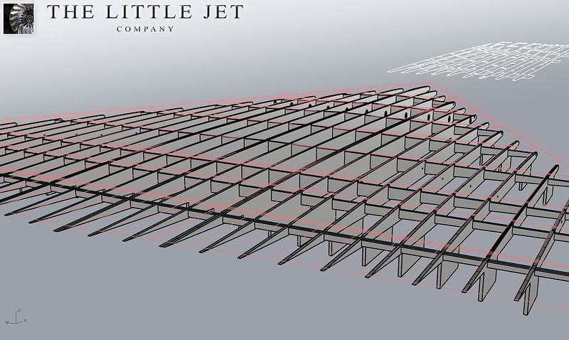
Initial CAD drawings were produced for the Wings and fin by FighterAces using the original aerofoil sections. The Little Jet Company then rendered the 2D drawing into three dimensional CAD work. Lift characteristics for the SeaDart delta wing are not impressive. These are symmetrical airfoil sections with a mean aerodynamic thickness of only 3.83%. The L/D is low at high angles of attack. I had a long conversations with the client regarding this and in the spirit of the project it was decided to go for a completely scale wing with blended aerofoils from root to tip using NACA-0003.30-65(Mod) and NACA-0004-65(Mod). The fin is very similar but uses NACA-0003.5-65(Mod) at the root. These are the exact aerofoils used on all five SeaDarts that were built. This is one of the very first supersonic delta wings designed and flown. Convair learnt a great deal from this and put this knowledge into some of their other iconic supersonic deltas.
 <script async src="//embedr.flickr.com/assets/client-code.js" charset="utf-8"></script>
 <script async src="//embedr.flickr.com/assets/client-code.js" charset="utf-8"></script>
This decision was helped along with the fact that we still had some holes in the research and areas of the model would need to be done with reference to photos alone, we believed an experienced team of professional modellers would have more success with this approach and have a sound understanding of whats required in a large complex model such as this. The SeaDart pattern is built purely by hand using scaled original drawings taken from the Convair Archives. All drawings were painstakingly digitally cleaned then enlarged to exactly 1/4 scale giving very good resolution and a decent start for making the pattern.
<script async src="//embedr.flickr.com/assets/client-code.js" charset="utf-8"></script>Our other custom composite jet projects will involve both CNC’d patterns and hand crafted external detail which offers a good solution for the manufacture of Carbon LTM tooling suitable for repeated use in an Autoclave.
Initial CAD drawings were produced for the Wings and fin by FighterAces using the original aerofoil sections. The Little Jet Company then rendered the 2D drawing into three dimensional CAD work. Lift characteristics for the SeaDart delta wing are not impressive. These are symmetrical airfoil sections with a mean aerodynamic thickness of only 3.83%. The L/D is low at high angles of attack. I had a long conversations with the client regarding this and in the spirit of the project it was decided to go for a completely scale wing with blended aerofoils from root to tip using NACA-0003.30-65(Mod) and NACA-0004-65(Mod). The fin is very similar but uses NACA-0003.5-65(Mod) at the root. These are the exact aerofoils used on all five SeaDarts that were built. This is one of the very first supersonic delta wings designed and flown. Convair learnt a great deal from this and put this knowledge into some of their other iconic supersonic deltas.
<script async src="//embedr.flickr.com/assets/client-code.js" charset="utf-8"></script><script async src="//embedr.flickr.com/assets/client-code.js" charset="utf-8"></script>
Last edited by Alex48; 10-03-2015 at 03:58 AM.
09-28-2015, 03:00 AM
#34
Thread Starter
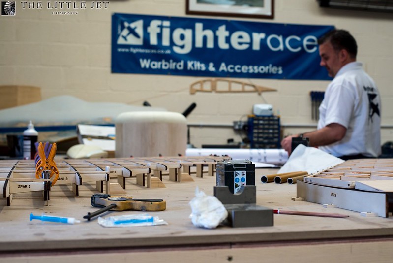
This moves us neatly over to phase two of the project which is the pattern. Having looked at numerous professional pattern making firms it became clear we needed someone who understood model aircraft and there is only one company here in the UK that I would trust with producing a pattern with the level of detail and accuracy that we require for this project.
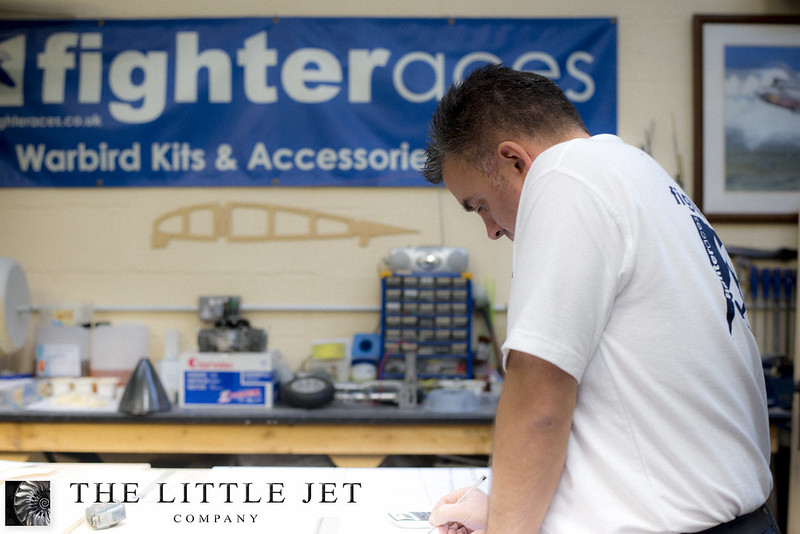
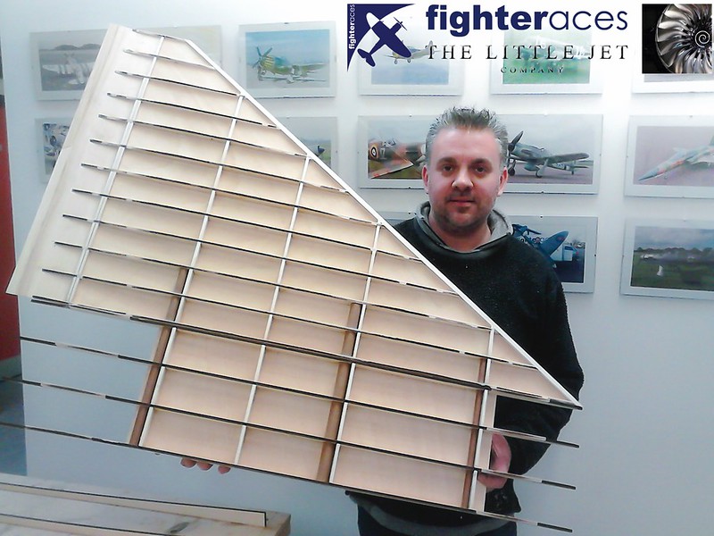
The team at Fighteraces run by the the very talented Phil Clarke (Pictured) was commissioned to build the pattern. We’ve worked with Fighteraces in the past so I was confident they could produce a stunning pattern to our very exacting standards.
 <script async src="//embedr.flickr.com/assets/client-code.js" charset="utf-8"></script>
For those of you that haven't heard of Fighteraces take a look at their website here.
http://www.fighteraces.co.uk/
They have produced some of the best piston engined scratch built models in the world and its a privilege working with them on the SeaDart.
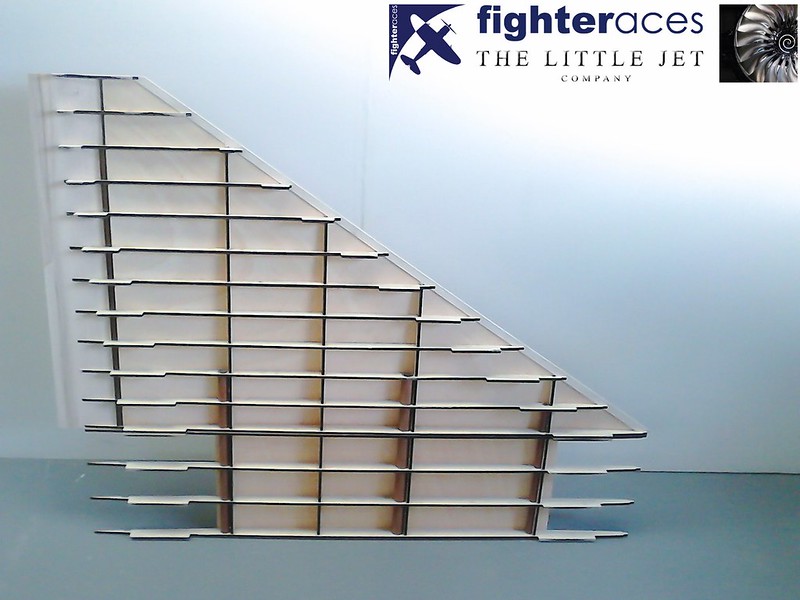
After months of solid research it finally begins... Lasercut parts for the fin using aerofoils NACA-0003.5-65(Mod) and NACA-0004-65(Mod).
 <script async src="//embedr.flickr.com/assets/client-code.js" charset="utf-8"></script>
Framed up ready for sheeting.
 <script async src="//embedr.flickr.com/assets/client-code.js" charset="utf-8"></script>
The team at Fighteraces run by the the very talented Phil Clarke (Pictured) was commissioned to build the pattern. We’ve worked with Fighteraces in the past so I was confident they could produce a stunning pattern to our very exacting standards.
<script async src="//embedr.flickr.com/assets/client-code.js" charset="utf-8"></script>For those of you that haven't heard of Fighteraces take a look at their website here.
http://www.fighteraces.co.uk/
They have produced some of the best piston engined scratch built models in the world and its a privilege working with them on the SeaDart.
After months of solid research it finally begins... Lasercut parts for the fin using aerofoils NACA-0003.5-65(Mod) and NACA-0004-65(Mod).
<script async src="//embedr.flickr.com/assets/client-code.js" charset="utf-8"></script>Framed up ready for sheeting.
<script async src="//embedr.flickr.com/assets/client-code.js" charset="utf-8"></script>
 09-29-2015, 12:09 AM
#37
Thread Starter
Thats why we commissioned him He has some great talent from the TV & Film world working for him on this as well. I've just come back from a two day visit to run through issues and see their progress on this and our 400cc GeeBeeZ.
So far so good...
He has some great talent from the TV & Film world working for him on this as well. I've just come back from a two day visit to run through issues and see their progress on this and our 400cc GeeBeeZ. So far so good...
Last edited by Alex48; 09-29-2015 at 04:23 AM.
09-30-2015, 03:58 PM
#38
Thread Starter
The fin is progressing well having the first half sheeted and a picture with Phil holding it so you can get a sense of scale.
 <script async src="//embedr.flickr.com/assets/client-code.js" charset="utf-8"></script>
 <script async src="//embedr.flickr.com/assets/client-code.js" charset="utf-8"></script>
It's worth noting the structure pictured is purely for the pattern and not necessarily representative of the flying model.
"The double rib marks the joint on the top of the fuselage.......the lower section will sit on top of the wing inside the fuselage (with a wing section shaped packed on it’s root end). This internal section will be cut down in chord.......the front rib sections will be removed back to the front face of the front spar.....the rear to just behind the rear tube."
Phil Clark, FighterAces
<script async src="//embedr.flickr.com/assets/client-code.js" charset="utf-8"></script><script async src="//embedr.flickr.com/assets/client-code.js" charset="utf-8"></script>It's worth noting the structure pictured is purely for the pattern and not necessarily representative of the flying model.
"The double rib marks the joint on the top of the fuselage.......the lower section will sit on top of the wing inside the fuselage (with a wing section shaped packed on it’s root end). This internal section will be cut down in chord.......the front rib sections will be removed back to the front face of the front spar.....the rear to just behind the rear tube."
Phil Clark, FighterAces
Last edited by Alex48; 10-02-2015 at 11:13 PM.
10-02-2015, 11:12 PM
#40
Thread Starter
"Initial construction starts with the vertical tail fin. All ribs have jigging tabs which were tack glued to the bench to ensure perfect alignment before the 1st skin was added.
Appearing maybe over engineered for a tail fin, but being a master pattern for a composite mould, weight is unimportant with this project whereas the structural stability of the finished component is the key. All laser cut parts are from 1/4" birch ply and the skins are 2mm liteply.......the finished fin is HEAVY but immensely stiff so ensuring there is no distortion during the mould making process.
The double rib marks the joint on the top of the fuselage.......the lower section will sit on top of the wing inside the fuselage (with a wing section shaped packed on it’s root end). This internal section will be cut down in chord.......the front rib sections will be removed back to the front face of the front spar.....the rear to just behind the rear tube.
Three tubes are fitted, 10 mm at the front, 20 in the middle and 16 at the rear. These are purely for alignment & fitting purposes only. They are unlikely to be used on the final flying version simply because they do not pass far enough up into the fin due to the thin section. Double if not triple full section blade type spar/joiners are likely to be used on the flying model.
The shear spars are all cut approx. 2 mm under size & they are faced in balsa that is easily sanded flush to the ribs. The LE is a section of hard 1/8” balsa notched onto the ribs......this gives the skin something to bond to at the LE + a larger base for the hard balsa LE block to bond to."
Phil Clark, FighterAces
10-05-2015, 10:32 AM
#41
Thread Starter
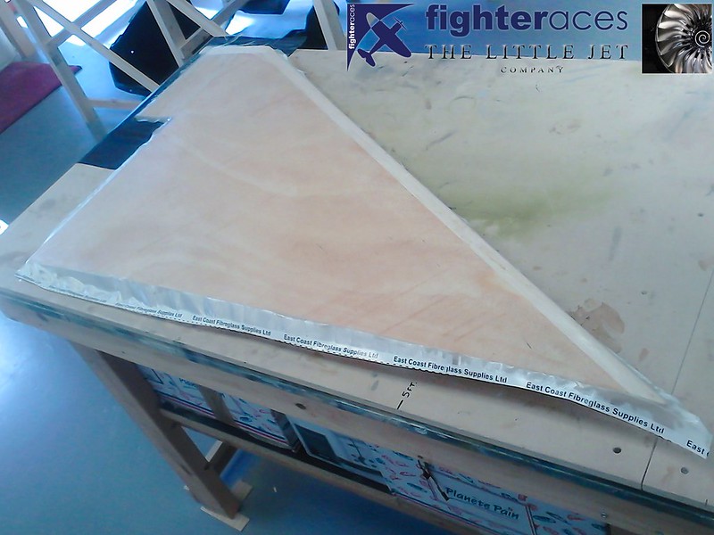
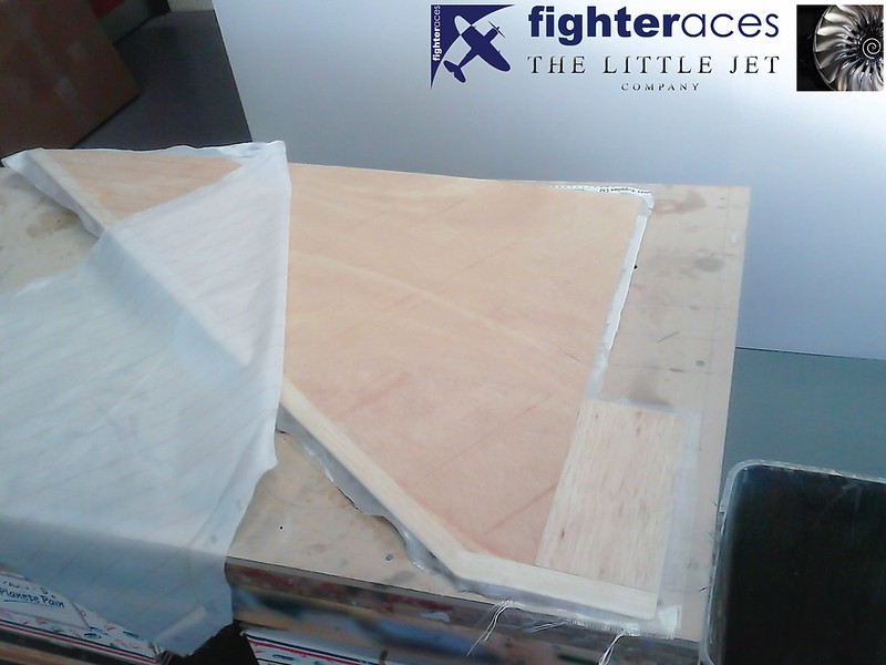
More progress from FighterAces on the SeaDart fin with the start of the glassing.
 <script async src="//embedr.flickr.com/assets/client-code.js" charset="utf-8"></script>
A peel ply layer which you can see folded back for demonstration only. Epoxy to come... Phil uses the excellent L285 skinning resin which I can highly recommend having used it myself on several projects.
 <script async src="//embedr.flickr.com/assets/client-code.js" charset="utf-8"></script>
A link to materials the Fighteraces team are using for the glassing etc...
http://www.fighteraces.co.uk/product...ing-materials/
<script async src="//embedr.flickr.com/assets/client-code.js" charset="utf-8"></script>A peel ply layer which you can see folded back for demonstration only. Epoxy to come... Phil uses the excellent L285 skinning resin which I can highly recommend having used it myself on several projects.
<script async src="//embedr.flickr.com/assets/client-code.js" charset="utf-8"></script>A link to materials the Fighteraces team are using for the glassing etc...
http://www.fighteraces.co.uk/product...ing-materials/
Last edited by Alex48; 10-05-2015 at 11:09 AM.
10-08-2015, 05:31 AM
#42
Thread Starter
"More progress with the fin following completion of the 2mm liteply skinning + hard balsa LE & tip blocks. Glassing is done with my favourite L285 skinning resin + a close weave 4oz cloth (as mentioned, weight not an issue, but component stability is). With the glass on, a layer of peel ply is then added (shown here partially removed post cure). This is wetted out with a 2nd application of resin but with the 1st layer + cloth still wet. The resin wets out the peel ply and once cured, the ply is ripped off leaving a beautifully smooth lightly textured surface that's ready for a light rub down & a 1st application of primer."
Phil Clark, FighterAces
Phil Clark, FighterAces
10-09-2015, 11:57 PM
#43
Thread Starter
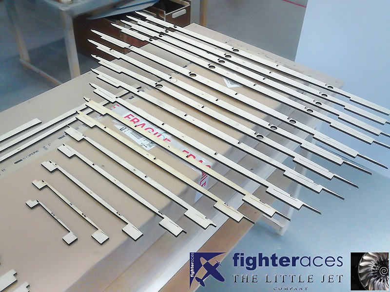
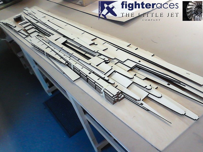
Laser cut parts for the wings... The root cord is around 8ft so these aren’t the smallest wings you'll ever see!
 <script async src="//embedr.flickr.com/assets/client-code.js" charset="utf-8"></script>
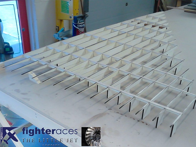
Framed up on jig tabs.
 <script async src="//embedr.flickr.com/assets/client-code.js" charset="utf-8"></script>
Phil Clark from Fighteraces hard at work on the SeaDart pattern.
 <script async src="//embedr.flickr.com/assets/client-code.js" charset="utf-8"></script>
<script async src="//embedr.flickr.com/assets/client-code.js" charset="utf-8"></script>Framed up on jig tabs.
<script async src="//embedr.flickr.com/assets/client-code.js" charset="utf-8"></script>Phil Clark from Fighteraces hard at work on the SeaDart pattern.
<script async src="//embedr.flickr.com/assets/client-code.js" charset="utf-8"></script>
10-12-2015, 01:40 AM
#44
Thread Starter
The wing panels are build identically to the fin.....1/4" ply ribs & shear spars, again with the spars cut 2mm underside so they can be faced in balsa to be easily levelled with the ribs prior to skinning.
Rib 4 has a duplicate as this is the break point between the removable outer panel & the centre section that is to be built into the fuselage.
With the scale section, we have a max root thickness (including the upper & lower 2mm skins) of only 70mm.......this means the ribs are quite flexible especially towards the top, so the jig tabs (glued directly to the bench) are vital to ensure a true panel is built.
Phil Clark, FighterAces
10-12-2015, 03:35 AM
#46
Thread Starter
Hi Bob, I'm pleased with the progress... The pattern will be finished by Christmas. In the New Year I'll be taking it to a company who will spend the day scanning the pattern so we have a digital copy. This will also mean we'll be able to accurately design the internal structure in CAD along with a CFD analysis of the design which will hopefully confirm our aerodynamic thoughts with regard to the model.
Lots to do...
Cheers
Lots to do...
Cheers
10-15-2015, 08:31 AM
#47
Thread Starter
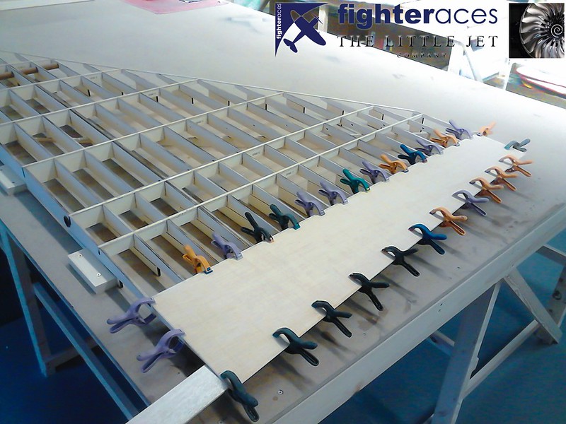
More from the team at Fighteraces... Sheeting has started with the elevon.
 <script async src="//embedr.flickr.com/assets/client-code.js" charset="utf-8"></script>
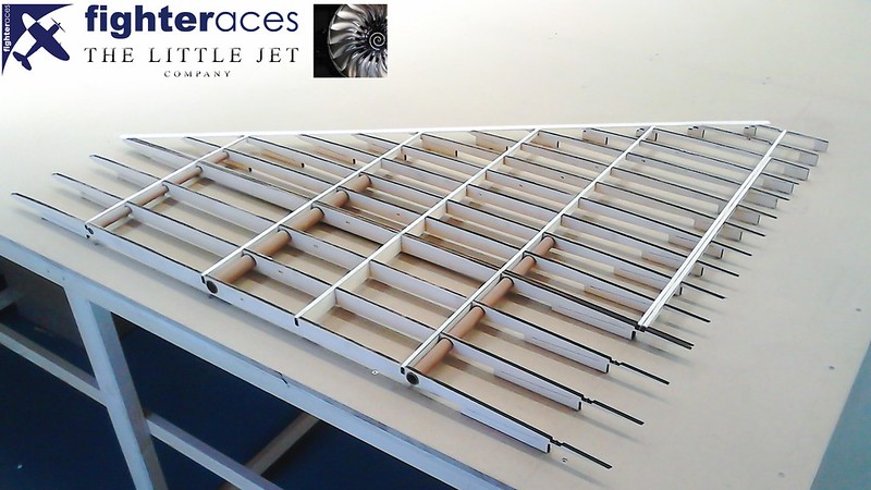
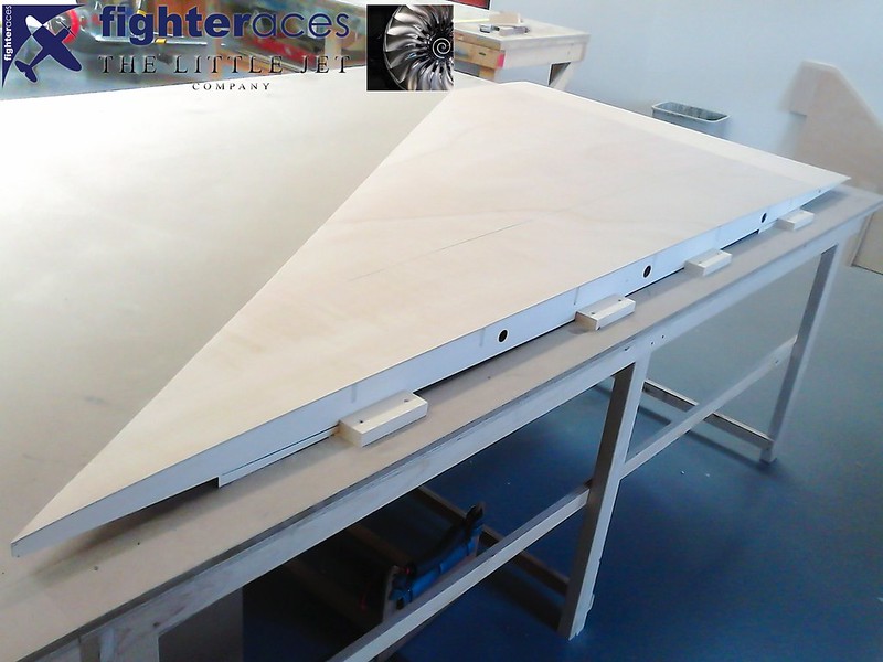
The finished right wing panel having had the top side sheeted in 2mm ply. Special jigs have been made to reverse the panel and sheet the underside.
 <script async src="//embedr.flickr.com/assets/client-code.js" charset="utf-8"></script>
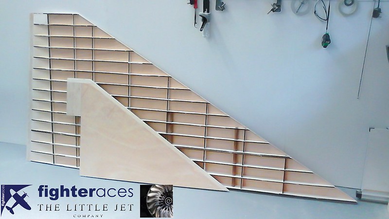
If you thought the fin was large this image shows it agianst the wing panel.
 <script async src="//embedr.flickr.com/assets/client-code.js" charset="utf-8"></script>
<script async src="//embedr.flickr.com/assets/client-code.js" charset="utf-8"></script>The finished right wing panel having had the top side sheeted in 2mm ply. Special jigs have been made to reverse the panel and sheet the underside.
<script async src="//embedr.flickr.com/assets/client-code.js" charset="utf-8"></script>If you thought the fin was large this image shows it agianst the wing panel.
<script async src="//embedr.flickr.com/assets/client-code.js" charset="utf-8"></script>
10-15-2015, 11:34 AM
#48
Thread Starter
"Not clear in the photo, but the elevons have the 'scale' 2 degrees reflex built in progressively from '0' at the root to 2 degree (TE up) at the tip. The elevon LE & false TE are built into the wing panel 1mm apart so the sheeted elevon can be cut off after the underside is sheeted. Also note the wedge shaped packer position centrally between the front & rear jig tabs to prevent sagging of the ribs when the top skin is added & weighted down to cure. All skin bonding is done with foaming PU 'Gorilla Glue'........giving plenty of working time & an excellent bond between ribs & skin.
Three wing tubes are used for alignment purposes as per the fin.......2 x 25mm and a smaller 20mm tube at the front. These pass as far out into the panel as is possible before breaking through the edges of the ribs at the tip end of the tubes. The 3 root rib bays will be mated to the corresponding 3 from the other panel to form a centre section that will be built integral to the fuselage."
Phil Clark, Fighteraces
 10-15-2015, 05:19 PM
#50
My Feedback: (6)
Alex
I can remember walking around that bird when it was in the shop but at that time I did not have a clue why the strange shape but that was when I was in my first year of collegeand about my third month in the experimental dept, live and learn.
Just more trivia
Cheers Bob T
I can remember walking around that bird when it was in the shop but at that time I did not have a clue why the strange shape but that was when I was in my first year of collegeand about my third month in the experimental dept, live and learn.
Just more trivia
Cheers Bob T