


Kingtech presents the all new T1 sports jet


 10-24-2018, 11:03 AM
#1853
12-09-2018, 11:38 AM
#1854
Junior Member
Join Date: Dec 2018
Posts: 2
Likes: 0
Received 0 Likes
on
0 Posts
Hello
I have newly bought K 210 engine
I inadvertently changed start parameters that shown on pictures in manual. I tried several start attemps but I could not start the engine.
İ use diesel fuel.
IEngine did not pass stage 2,attemptng start, rpm hang about 3500 after that again ignition phase start. At last timed out appears need factory start parameters.
Any help will be appreciated.
Thanks in advance
Best Regards
01-01-2019, 10:54 AM
#1856

My Feedback: (13)
Join Date: Apr 2002
Location: Chico, CA,
Posts: 186
Likes: 0
Received 0 Likes
on
0 Posts
T3chdad,
you look like you're way ahead of me on this build and knowledge.. Having no luck getting the lighting system to work. Can you help with some instruction for the setup?
Appreciate any help..
Thank you
you look like you're way ahead of me on this build and knowledge.. Having no luck getting the lighting system to work. Can you help with some instruction for the setup?
Appreciate any help..
Thank you

 01-02-2019, 07:33 AM
#1859

I'm afraid that I don't have experience with that system. I'll see if I can find you some help though...
01-02-2019, 09:32 AM
#1860

 01-02-2019, 04:46 PM
#1862

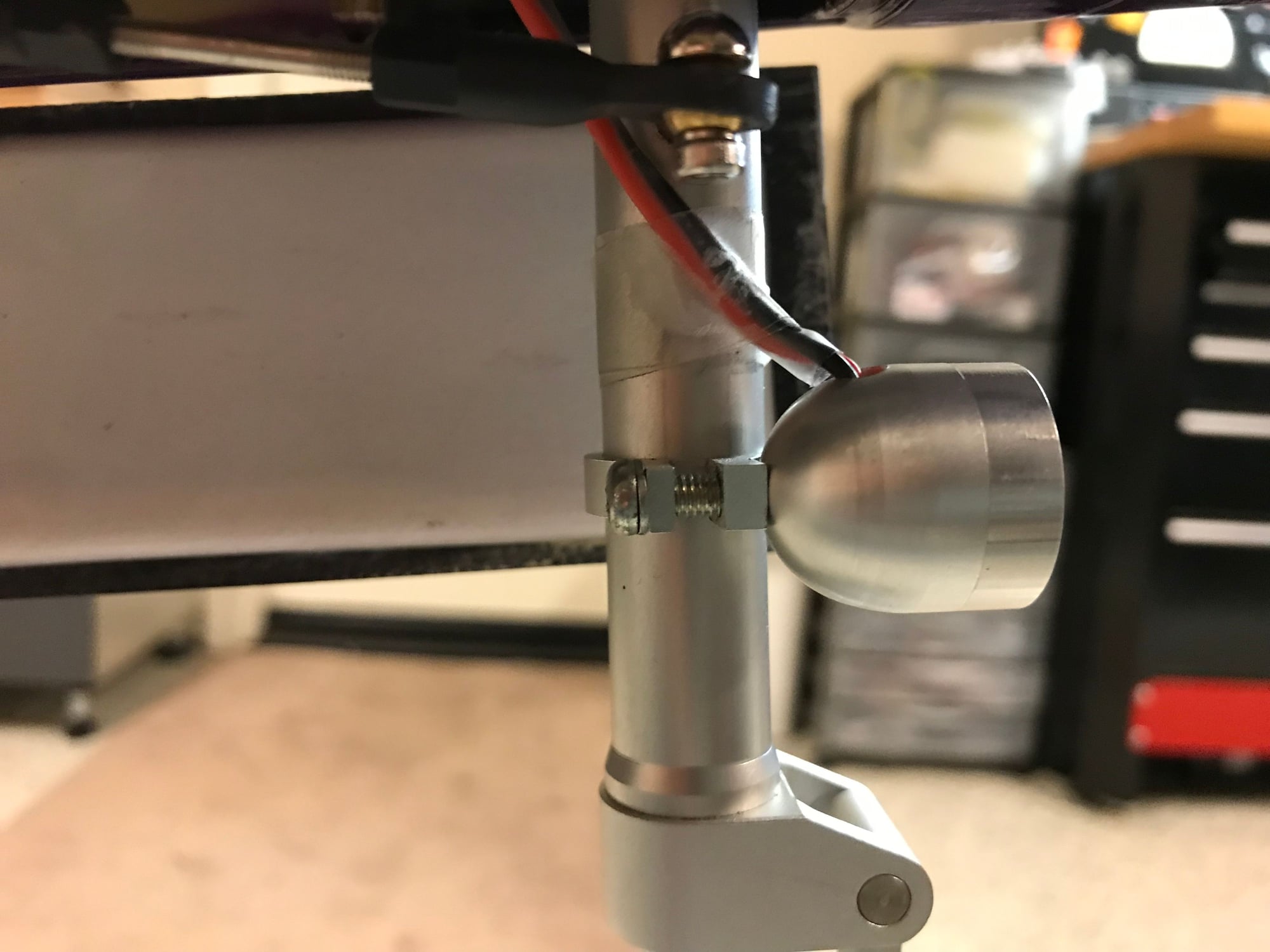
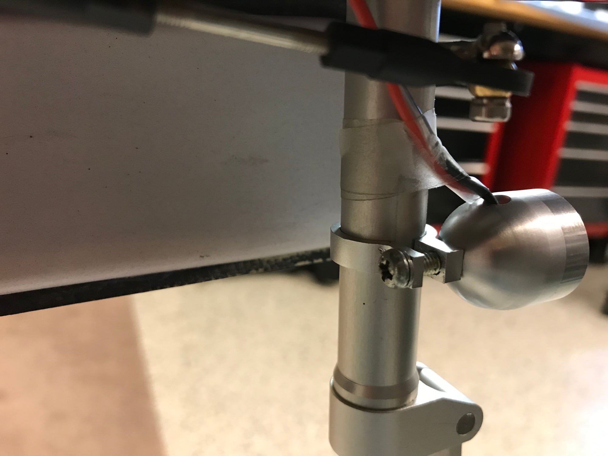
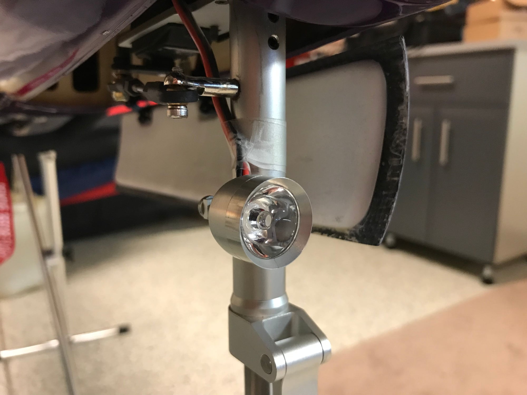
Hey folks. Can anyone please post a picture of how you mounted your nose gear light that came with the light kit install option. Also, the Y that is supplied with the nose gear light, one side goes to the light, the other side goes where? Basically, how do you hook up the whole nose gear light wiring harness.
Thank you
tom
Thank you
tom
01-08-2019, 06:15 AM
#1863
My Feedback: (1)

Join Date: Mar 2002
Location: Scotia, NY NY
Posts: 74
Likes: 0
Received 0 Likes
on
0 Posts
Hey folks. Can anyone please post a picture of how you mounted your nose gear light that came with the light kit install option. Also, the Y that is supplied with the nose gear light, one side goes to the light, the other side goes where? Basically, how do you hook up the whole nose gear light wiring harness.
Thank you
tom
Thank you
tom
Tom, with regards to the landing light wiring, one wire goes to the controller constant on if you wish, or can go directly to a battery. The other wire goes to the receiver channel associated with the gear. That will ensure that the light is only on with the gear down. I had to try connecting the wires to find out which was which and of course had it backwards the first time. I labeled the wires after I had it working properly.
01-08-2019, 07:18 PM
#1868
I want to ask if anyone has any pictures of the light install as well. I wanted to see how the top and bottom lights were mounted by the factory as well as how the nose gear / landing light was mounted. I decided to purchase the lighting kit after i received the plane.
Tom, with regards to the landing light wiring, one wire goes to the controller constant on if you wish, or can go directly to a battery. The other wire goes to the receiver channel associated with the gear. That will ensure that the light is only on with the gear down. I had to try connecting the wires to find out which was which and of course had it backwards the first time. I labeled the wires after I had it working properly.
Tom, with regards to the landing light wiring, one wire goes to the controller constant on if you wish, or can go directly to a battery. The other wire goes to the receiver channel associated with the gear. That will ensure that the light is only on with the gear down. I had to try connecting the wires to find out which was which and of course had it backwards the first time. I labeled the wires after I had it working properly.
good evening and thank you for getting back to me. I got all the lights figured out! Nose gear goes up, light goes out! Works great! When I get home, I�ll take a photo to show how I mounted the nose gear light. What I can�t figure out, with the lights assigned to a switch on my radio to turn them on/off, I always cycle through MODE A, B, and C. It�s like I�m using the manual button on the lighting control unit! Lights are super bright! Taxied it around the street last night, looks awesome!
 01-14-2019, 08:45 PM
#1871
My Feedback: (28)
Expect at least 6-8 weeks since each one is produced painted and polished after you order it. They don't have unpainted planes laying around waiting on orders. Remember all of the stuff you see on the plane is paint and not decals, and each one is hand polished before it is packed. They are worth the wait.
02-21-2019, 01:43 PM
#1872
I bought a Yellow Monster T1 with the light package a couple months ago and wanted to pass on a few pointers in figuring out the included light controller. The light controller is branded by what looks like �Uneng� although it appears to be identical to the Pilot RC LED Navigation Light Controller. The manual for the controller can be found at the Pilot RC web site under accessories and manuals. The manual describes how to set up the controller and the three modes of operation: A - all LEDs on; B - solid lights off, strobe and flash on; and C - all lights off. You can switch among these modes by either pressing the Switch (button) on the controller or changing the radio channel output (if used) - the Radio(Light) input on the controller connected to a spare RX channel. Here are a few things I learned that may be of some help:
1. The operating voltage range for the controller is specified as 7.4 - 8.4 V. I tried a 2 cell LiFe (wanting to use all LiFe batteries) and as expected it did not work. However I did not encounter any incompatibilities with different voltages in using 2 cell LiFes on the Specteum PowerSafe RX and a separate 2 cell LiPo on the light controller.
2. The landing light had two servo leads which appeared identical and were unmarked. I believe one is for the controller (No Flash) output and the other is to be Y�ed to the Gear channel (to turn the landing light off and on when the gear are up or down, respectively). To determine which was which, I left one unconnected at first and connected the other to the controller, since they were unmarked. The correct lead should cause the landing light to come on. The controller appears to default in the gear down position on power up so ensure you have the TX set with gear down when powering up.
3. I wanted to set up my TX with a switch to separately control the lights as on (Mode A) or off (Mode B). This appeared problematic as the controller uses RX output changes or transitions instead of fixed values, such as +100%, 0%, -100% to set the three modes. I determined a way to use a switch by using the Spektrum TX Sequencer function to provide two transitions in the forward Sequencer direction (which will change from Mode A to B to C). Works fine in turning the lights from on to off. The problem is in the reverse direction you need one transition to get back to Mode A (lights on), yet one transition would put you back at an incorrect level, such as -100% instead of +100% which is where you need to be for the Sequencer. So ... I used four transitions in the reverse direction, which then gets you from Mode C to Mode A, albeit the long way (C -> A -> B -> C -> A) and at the correct level for the Sequencer enabling it to repeat. Perhaps someone knows an easier or better way, but I now have a two-position switch on my TX that controls all lights with the landing light also controlled by the gear position!
02-27-2019, 02:37 AM
#1873
My Feedback: (23)
Expect at least 6-8 weeks since each one is produced painted and polished after you order it. They don't have unpainted planes laying around waiting on orders. Remember all of the stuff you see on the plane is paint and not decals, and each one is hand polished before it is packed. They are worth the wait.
02-27-2019, 08:35 AM
#1874
Sorry for a near duplicate post. I tried to edit my post below to correct a mistake and a typo but the edit function will not allow it. So ... I've included the corrections below as well as some additional info and clarifications.
I bought a Yellow Monster T1 with the light package a couple months ago and wanted to pass on a few pointers in figuring out the included light controller. The light controller is branded by what looks like �Uneng� although it appears to be identical to the Pilot RC LED Navigation Light Controller. The manual for the controller can be found at the Pilot RC web site under accessories and manuals. The manual describes how to set up the controller and the three modes of operation: A - all LEDs on; B - solid lights off, strobe and flash on; and C - all lights off. You can switch among these modes by either pressing the Switch (button) on the controller or changing a radio channel output (if used) - the Radio(Light) input on the controller connected to a spare RX channel. Here are a few things I learned that may be of some help:
1. The operating voltage range for the controller is specified as 7.4 - 8.4 V. I tried a 2 cell LiFe (wanting to use all LiFe batteries) and as expected it did not work. However I did not encounter any incompatibilities with different voltages in using 2 cell LiFes on the Spektrum PowerSafe RX and a separate 2 cell LiPo on the light controller. With the top fuse light on strobe, the bottom fuse light on flash, and the two wing lights and landing light on continuous or solid (No Flash), the battery current was measured at 162 mA, so a large battery for lights is not required. With the lights off, the current still measured 15 mA so you do need to disconnect the battery at the end of the day. (Given the light battery is a LiPo, I believe removing it from the plane at the end of the day is a good practice regardless.)
2. The landing light had two servo leads which appeared identical and were unmarked. I believe one is for the controller (No Flash) output and the other is to be Y�ed to the Gear channel (to turn the landing light off and on when the gear are up or down, respectively). To determine which was which, I left one unconnected at first and connected the other to the controller, to determine which lead was which. The correct lead should cause the landing light to come on. The controller appears to default in the gear down (Landing Light on) position on power up so ensure you have the TX set with gear down when powering up.
3. I wanted to set up my TX with a switch to separately control the lights as on (Mode A) or off (Mode C). I was not interested in Mode B control from the TX. This appeared problematic as the controller uses RX output changes or transitions instead of fixed values, such as +100%, 0%, -100% to set the three modes. I determined a way to use a TX switch by using the Spektrum TX Sequencer function to provide two transitions in the forward Sequencer direction (which will change from Mode A to B to C). This works fine in turning the lights from on to off. The problem is in the reverse direction you need one transition to get back to Mode A (lights on), yet one transition would put you back at an incorrect level, such as -100% instead of +100% which is where you need to be for the Sequencer. So ... I used four transitions in the reverse direction, which then gets you from Mode C to Mode A, albeit the long way (C -> A -> B -> C -> A) and at the correct level for the Sequencer enabling it to repeat. Perhaps someone knows an easier or better way, but I now have a two-position switch on my TX that controls all lights with the landing light also controlled by the gear position!