


Bavarian Demon Cortex PRO is here!!


 03-15-2017, 09:19 AM
#106

My Feedback: (22)
Join Date: Jun 2003
Location: Sun City West, AZ
Posts: 224
Likes: 0
Received 0 Likes
on
0 Posts
Paul is correct, gyro functions perfectly but you loose all the functionality of the CB 200 ie programming has to be done before you insert the Cortex Pro in series.
03-15-2017, 06:59 PM
#107
I just received test FW for the Cortex Pro that enables telemetry and integration via Device Explorer. I'm at FL Jets this week but I'll post some screen shots when I can.
Last edited by F1 Rocket; 03-15-2017 at 07:51 PM.

 03-18-2017, 05:54 AM
#111

From the looks of the screen shots it seem there is a single stick priority setting instead of separate priorities for each axis ? Is there at least a separate stick priority setting for each bank ? Do you have greater control f these setting if you use a PC interface ?
 03-18-2017, 09:13 AM
#112
From the looks of the screen shots it seem there is a single stick priority setting instead of separate priorities for each axis ? Is there at least a separate stick priority setting for each bank ? Do you have greater control f these setting if you use a PC interface ?
All tuning parameters from the PC software are provided in the device explorer interface. There is no difference.
Last edited by F1 Rocket; 03-18-2017 at 09:18 AM.
03-19-2017, 02:16 AM
#115

I have the Cb 200 and the new Cortex Pro. I just must clear something for me. Does the Ext work for example the speed sensor or could I not use the Ext at all before the update?
 03-19-2017, 12:15 PM
#117
My Feedback: (3)
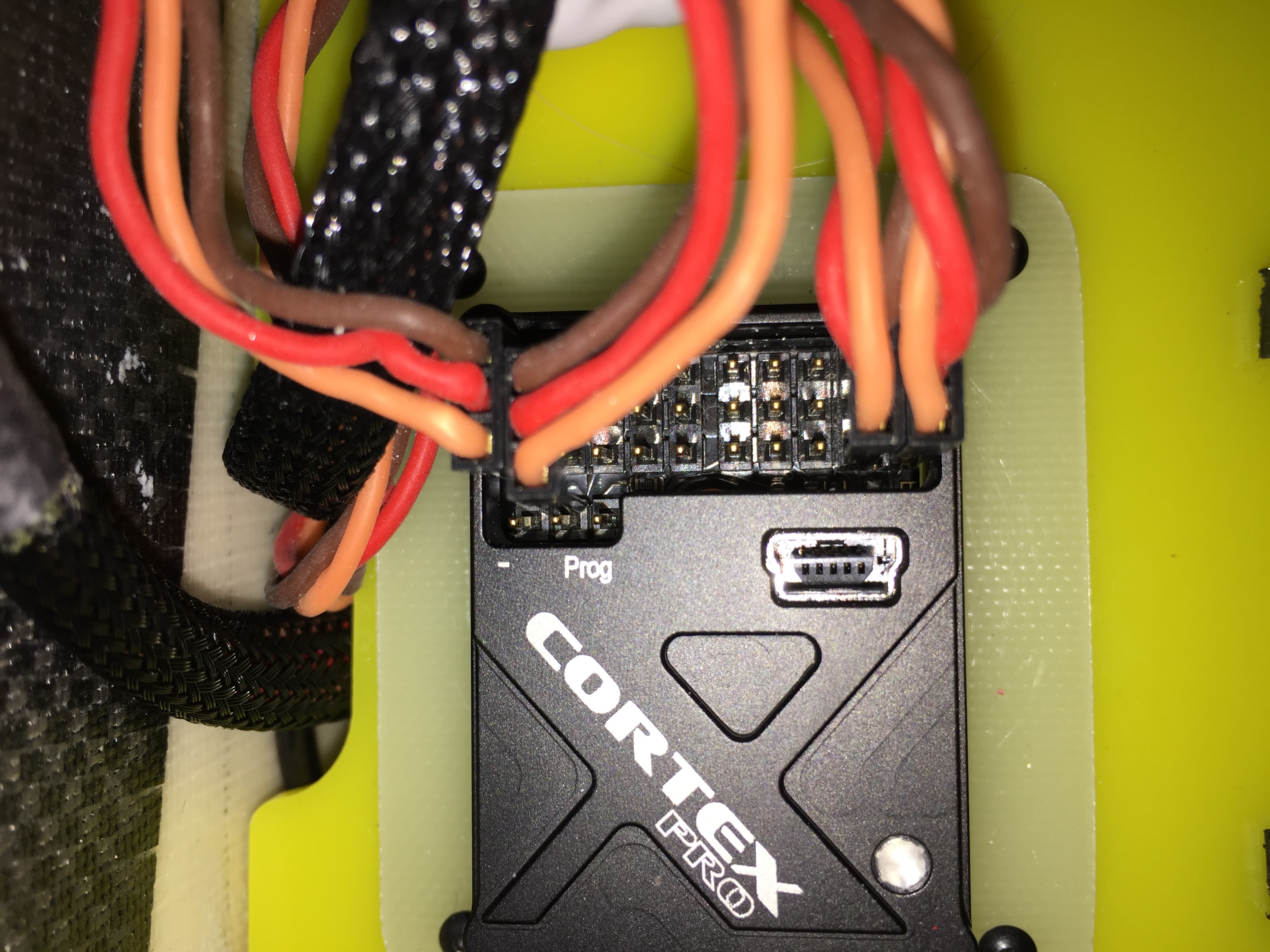
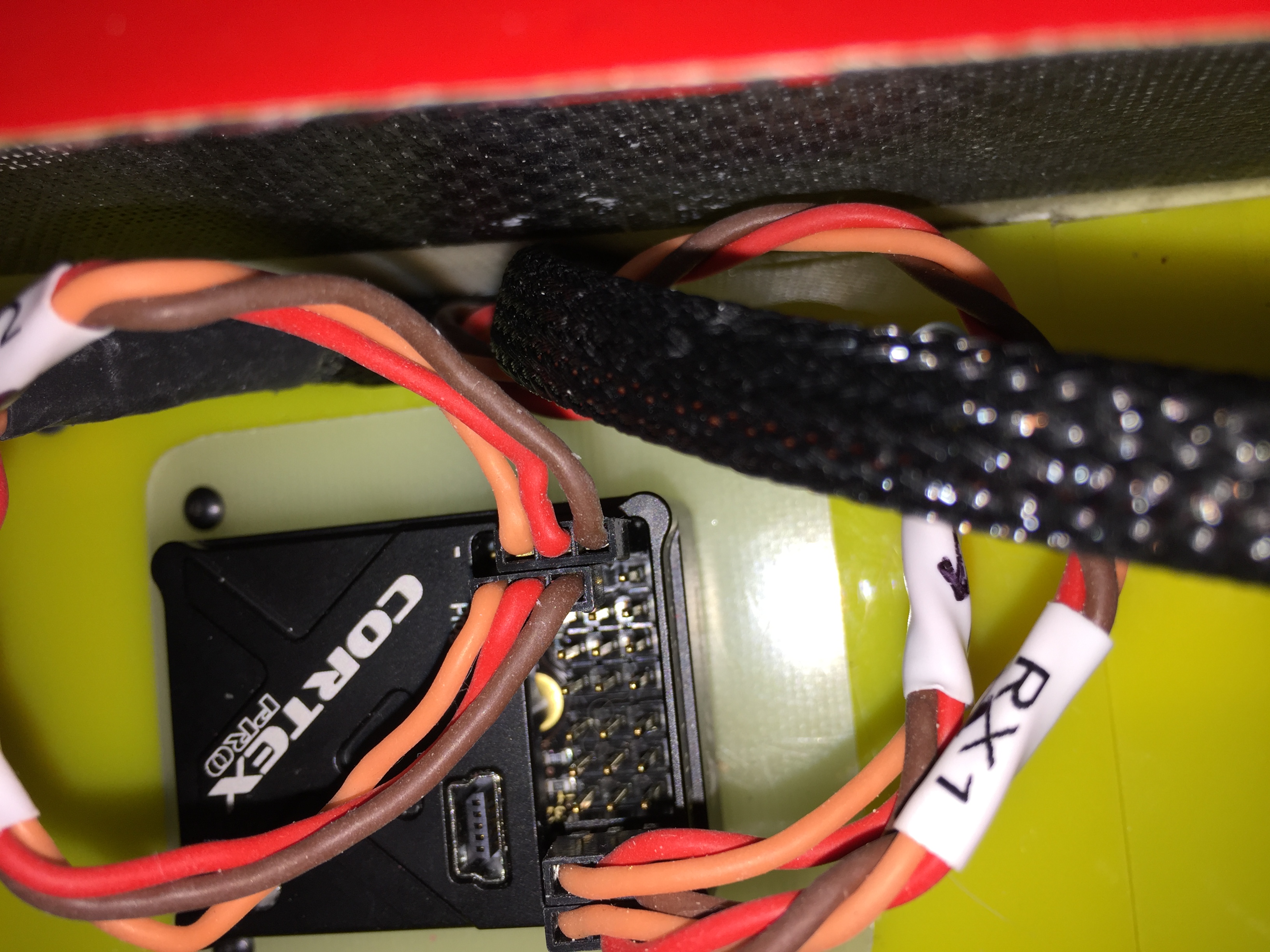
A word of caution with the Cortex Pro.
Due to the case and circuit board design, it is very easy to mis-pin the 3 connectors next to the bind socket.
Internally to the gyro, it appears that the +ve and -ve power lines are shared across all connectors, so by mis-pinning one of the connectors that are used to supply power to the gyro (such as when using a dual bus configuration from Jeti) you end up shorting out the power supply to the gyro.
I burned up and destroyed a Jeti CB200 by inadvertently mis-pinning the gyro. The CB200 showed that I drew over 28A and burned it out. It has taken me a while to figure out how I did it, but luckily I found it when I didn't have the CB200 powered up, otherwise the replacement CB200 would have suffered the same fate.
A simple design error that cost me a $200 CB200.
I would recommend that the case and/ or circuit board be redesigned to prevent a mis-pinning of the 3 sockets adjacent to the bind socket.
Photos attached.
Paul
This will prevent any chance of misalignment that you unfortunately experienced.
The 3 pins will gave more than sufficient retention force on the pins to stay in place until removed for binding/programming.
03-20-2017, 05:23 AM
#121
If you are connecting digital servos directly to the Cortex Pro use 166Hz if you don't know the servo spec. If you are using a serial connection to a Central Box you will set this in the Central Box itself.
Last edited by F1 Rocket; 03-20-2017 at 05:27 AM.
03-21-2017, 08:29 AM
#123
A word of caution with the Cortex Pro.
Due to the case and circuit board design, it is very easy to mis-pin the 3 connectors next to the bind socket.
Internally to the gyro, it appears that the +ve and -ve power lines are shared across all connectors, so by mis-pinning one of the connectors that are used to supply power to the gyro (such as when using a dual bus configuration from Jeti) you end up shorting out the power supply to the gyro.
I burned up and destroyed a Jeti CB200 by inadvertently mis-pinning the gyro. The CB200 showed that I drew over 28A and burned it out. It has taken me a while to figure out how I did it, but luckily I found it when I didn't have the CB200 powered up, otherwise the replacement CB200 would have suffered the same fate.
A simple design error that cost me a $200 CB200.
I would recommend that the case and/ or circuit board be redesigned to prevent a mis-pinning of the 3 sockets adjacent to the bind socket.
Photos attached.
Paul
Due to the case and circuit board design, it is very easy to mis-pin the 3 connectors next to the bind socket.
Internally to the gyro, it appears that the +ve and -ve power lines are shared across all connectors, so by mis-pinning one of the connectors that are used to supply power to the gyro (such as when using a dual bus configuration from Jeti) you end up shorting out the power supply to the gyro.
I burned up and destroyed a Jeti CB200 by inadvertently mis-pinning the gyro. The CB200 showed that I drew over 28A and burned it out. It has taken me a while to figure out how I did it, but luckily I found it when I didn't have the CB200 powered up, otherwise the replacement CB200 would have suffered the same fate.
A simple design error that cost me a $200 CB200.
I would recommend that the case and/ or circuit board be redesigned to prevent a mis-pinning of the 3 sockets adjacent to the bind socket.
Photos attached.
Paul
Cheers
Alan
03-24-2017, 12:33 AM
#125
For jeti users, not yet there but close, see the message I got this morning from Bavarian Demon team on questionning for full Jeti support
We are very close, it�s probably another 1-2 weeks. Only final testing, plus Jeti needs to create the update file for the Tx. That�s it. Should be not long any more.
And believe me: I am looking forward to this more than anyone else J
Thanks for your appreciation and sorry for all the wait,
We are very close, it�s probably another 1-2 weeks. Only final testing, plus Jeti needs to create the update file for the Tx. That�s it. Should be not long any more.
And believe me: I am looking forward to this more than anyone else J
Thanks for your appreciation and sorry for all the wait,