


mig 15 1/4 scale composite


 08-24-2017, 01:02 AM
#85
I guessed it when i see your wing tubes that you will be placing it in the rear.
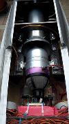
This is how the first generation CARF Mig-15 had the engine...it makes very big problem in balancing.
It needed more than 3kg in nose to balance correct . Maybe you would like to do a google search about it...it was big problem
http://www.rcuniverse.com/forum/rc-j...-cg-again.html
http://www.rcuniverse.com/forum/rc-j...-released.html
http://www.rcuniverse.com/forum/rc-j...-mig-15-a.html
They changed the design and move engine forward:
http://carf-models.com/files/product/18/2b/e0/12.jpg
MiG-15 Fagot 1:5
" The turbine has been moved forward by considerable 30 cm (12"). This gurantees that less balance lead is required to obtain the correct CG. ."
Now many owners including me we are moving even more forward the engine to eliminate the use of balancing lead.
I flew some Mig15's and the ones with this modification fly 100% better..lighter and less stress to the landing gear..
I can send you photos of the engine frames i made if u r interesting .
Again congratulations to your amazing skills and mig!
Last edited by DelGatoGrande; 08-24-2017 at 01:05 AM.
08-24-2017, 01:18 AM
#86

Thread Starter
Join Date: Sep 2013
Posts: 631
Likes: 0
Received 0 Likes
on
0 Posts
I guessed it when i see your wing tubes that you will be placing it in the rear.
This is how the first generation CARF Mig-15 had the engine...it makes very big problem in balancing.
It needed more than 3kg in nose to balance correct . Maybe you would like to do a google search about it...it was big problem
http://www.rcuniverse.com/forum/rc-j...-cg-again.html
http://www.rcuniverse.com/forum/rc-j...-released.html
http://www.rcuniverse.com/forum/rc-j...-mig-15-a.html
They changed the design and move engine forward:
http://carf-models.com/files/product/18/2b/e0/12.jpg
MiG-15 Fagot 1:5
" The turbine has been moved forward by considerable 30 cm (12"). This gurantees that less balance lead is required to obtain the correct CG. ."
Now many owners including me we are moving even more forward the engine to eliminate the use of balancing lead.
I flew some Mig15's and the ones with this modification fly 100% better..lighter and less stress to the landing gear..
I can send you photos of the engine frames i made if u r interesting .
Again congratulations to your amazing skills and mig!
Attachment 2229264
Attachment 2229265
i will fly like this now and i will see how much balancing need in nouse ,next ones i will change for good balancing😊.thank you
08-24-2017, 05:37 AM
#87
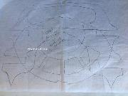
Here is my design for the CARF MIG-15.
Maybe one day i will brake out the frond frame and make new following the - - - - - - - - - - lines.
For two reasons. It allows room for bigger turbine like p160 ,the ideal engine for the CARF size as the p100 cant loop it.
It allows room to raise the engine to have "neutral thrust" as the normal mounting gives "up thrust".
08-24-2017, 05:59 AM
#89
Thread Starter
Join Date: Sep 2013
Posts: 631
Likes: 0
Received 0 Likes
on
0 Posts
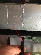
made out of multiple sheets of 3mm ply
Attachment 2229276
Closing the pocket.Its oversized as seen in the draw to give room for alingment .In there you put the fibreglass tubes u have already made and fill all pocket with epoxy
Attachment 2229277
Attachment 2229278
Attachment 2229276
Closing the pocket.Its oversized as seen in the draw to give room for alingment .In there you put the fibreglass tubes u have already made and fill all pocket with epoxy
Attachment 2229277
Attachment 2229278
08-24-2017, 06:02 AM
#90
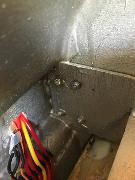
last photo is the carbon wing tubes... if you ever need to make this modification ,it would be good to cut a small line across the the tube so the air can come out while you inserting it.
Or while resin is still fresh you risk to pump air in the pocket when inserting or vacuum resin in the fibreglass tube while you remove it.
sorry for the poor english ..good luck!
Or while resin is still fresh you risk to pump air in the pocket when inserting or vacuum resin in the fibreglass tube while you remove it.
sorry for the poor english ..good luck!
08-24-2017, 06:17 AM
#96
I have fly quite a few jet models .I guaranty your. mig will fly absolutely amazing .The wing is just huge.
Just keep it light and use a p160 engine.
You might want to look also the last frame supporting the fin that goes all the way in fuselage.
http://carf-models.com/files/product...uctions_v2.pdf
and here is internal wing support of carf as suggestion
goodluck
08-24-2017, 09:20 AM
#97
Thread Starter
Join Date: Sep 2013
Posts: 631
Likes: 0
Received 0 Likes
on
0 Posts
I have fly quite a few jet models .I guaranty your. mig will fly absolutely amazing .The wing is just huge.
Just keep it light and use a p160 engine.
You might want to look also the last frame supporting the fin that goes all the way in fuselage.
http://carf-models.com/files/product...uctions_v2.pdf
and here is internal wing support of carf as suggestion
Attachment 2229284
goodluck
Just keep it light and use a p160 engine.
You might want to look also the last frame supporting the fin that goes all the way in fuselage.
http://carf-models.com/files/product...uctions_v2.pdf
and here is internal wing support of carf as suggestion
Attachment 2229284
goodluck