


New Sport Jet: T-One Models Mini Fortune / Mini T1

 01-03-2019, 06:16 PM
#829

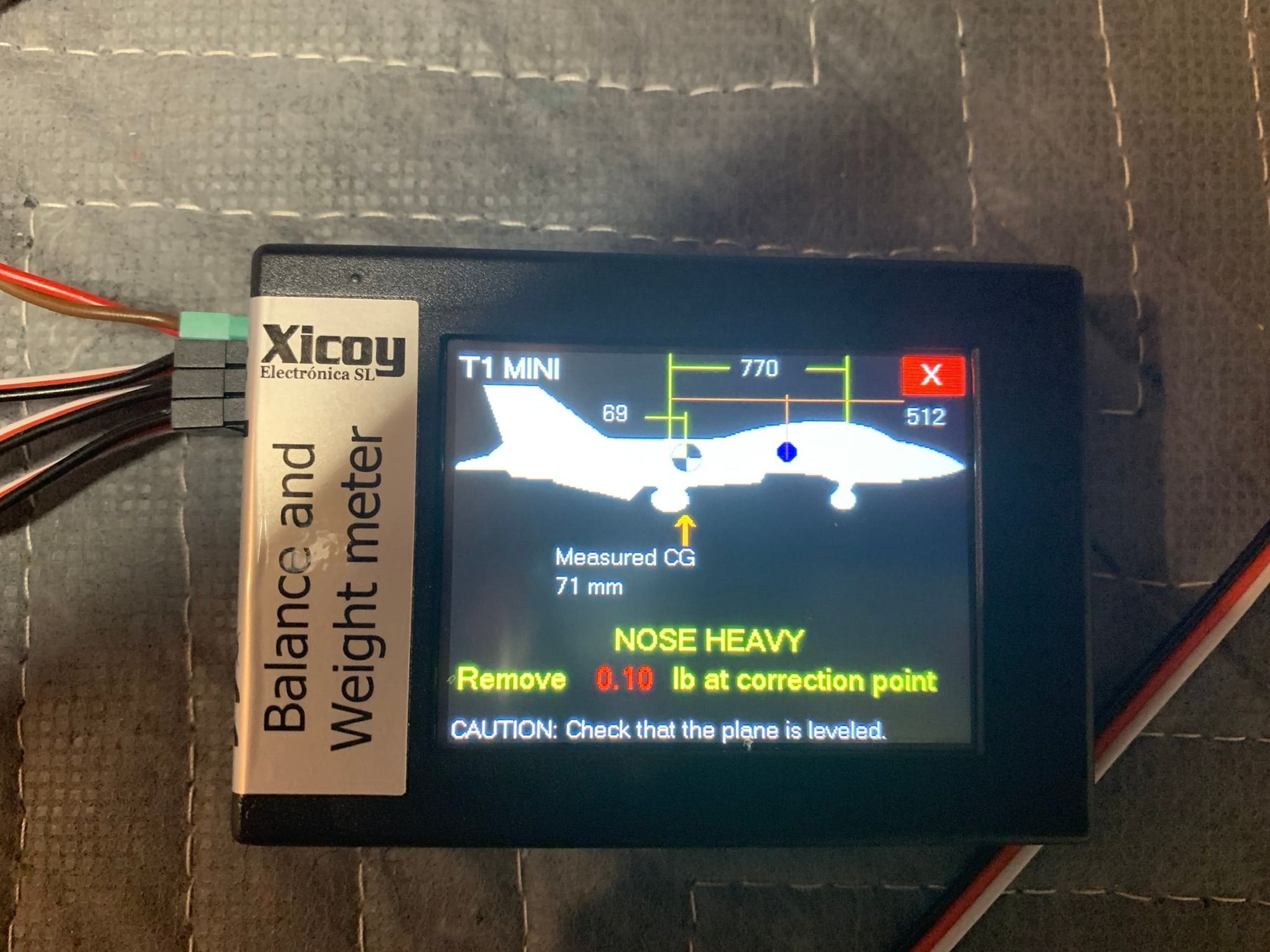
I think the range you want to shoot for is 200-210, 190 I think was considered by everyone that flew it to be too nose heavy. The way I measured it with the Xicoy, 69mm was where the CG would be at 210. I ended up at 73mm (the pic says 71 but that was with an empty UAT) which puts my CG @ 206mm as long as I measured right. I have yet to maiden mine but I think 206 will be plenty safe.
Last edited by camss69; 01-03-2019 at 06:19 PM.
01-03-2019, 07:24 PM
#831
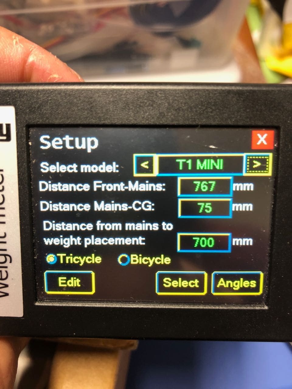
Here are my Xicoy settings for comparison:
 01-03-2019, 07:38 PM
#832

Join Date: Jan 2011
Location: Benbrook, TX
Posts: 48
Likes: 0
Received 0 Likes
on
0 Posts
Tom,
I appreciate you sharing these numbers and insight. I would prefer it to be slightly nose heavy as opposed to tail heavy. As it sits right now with an empty main tank and no batshare I'm at 17 lbs and the measured CG is at 84mm which if I'm thinking correctly gives me a CG at 186mm. This is with all three batteries on the tray above the NLG. I know this isn't where I want to be and will fix it. I had to walk away from it for a little while lol.
I'm measuring the leading edge where it begins on the fuselage and coming up with this number. I need to get my wife to try and help me balance it with our fingers to see where it ends up.
Zach
Last edited by firehawkzach; 01-03-2019 at 07:41 PM.
01-03-2019, 07:51 PM
#833
Tom,
I appreciate you sharing these numbers and insight. I would prefer it to be slightly nose heavy as opposed to tail heavy. As it sits right now with an empty main tank and no batshare I'm at 17 lbs and the measured CG is at 84mm which if I'm thinking correctly gives me a CG at 186mm. This is with all three batteries on the tray above the NLG. I know this isn't where I want to be and will fix it. I had to walk away from it for a little while lol.
I'm measuring the leading edge where it begins on the fuselage and coming up with this number. I need to get my wife to try and help me balance it with our fingers to see where it ends up.
Zach
I appreciate you sharing these numbers and insight. I would prefer it to be slightly nose heavy as opposed to tail heavy. As it sits right now with an empty main tank and no batshare I'm at 17 lbs and the measured CG is at 84mm which if I'm thinking correctly gives me a CG at 186mm. This is with all three batteries on the tray above the NLG. I know this isn't where I want to be and will fix it. I had to walk away from it for a little while lol.
I'm measuring the leading edge where it begins on the fuselage and coming up with this number. I need to get my wife to try and help me balance it with our fingers to see where it ends up.
Zach
If you look back through this thread you find a significant amount of discussion regarding CG. I finally gave up trying to make sense of it all and just flew the darn thing, I figured if I was a little nose heavy it would not be fatal (not necessarily true if you are too tail heavy), and I was right. I've got my two receiver batteries over the NLG (2x2600 mah Fromeco Li-Ions) and my turbine battery on top of the fuel tank. My fuel pump and UAT are immediately in front of the fuel tank. This config puts the CG right where I like it, the jet flies nice with no tendency to snap in tight turns, and it flares very nicely on landing. If you have all three batteries plus your fuel pump over the NLG you might be a little too nose heavy in that config. At the end of the day I would not worry too much about getting the CG exact for the first few flights, just try to get it in the ballpark and then adjust it to your preference. You are going to love this jet!
Tom
01-03-2019, 08:14 PM
#834
Join Date: Jan 2011
Location: Benbrook, TX
Posts: 48
Likes: 0
Received 0 Likes
on
0 Posts
Tom,
Thank you for that and I'm terribly excited as you can probably tell from all my posts. I played musical batteries and put my square ECU battery just forward of the fuel tank and my two receiver batteries above the NLG. This gets me to 192 so I know I'm getting closer. I'm thinking the batshare on the forward tray may give me enough to move all batteries by the UAT and fuel tank to balance her out. I can always bring the fuel pump down from the tray above the NLG and help give me a little push towards 195. Batshare comes Monday and I'll be in Wichita all next week so progress will halt after the engine run and taxi this weekend.
Zach
01-04-2019, 11:14 PM
#835
Join Date: Jan 2011
Location: Benbrook, TX
Posts: 48
Likes: 0
Received 0 Likes
on
0 Posts
Don't bother with any lubricant...it won't improve the problem. It is NOT the JP controller. I have spent hours investigating this issue and I am confident that I have found both the cause and a solution. The problem boils down to competing magnetic forces and requires a simple physical modification to resolve.
Problem:
What seemed to be a great design didn't work out so well in practical application. There are two competing magnetic forces...the electromagnetic brake core and three tiny-but-strong magnets in the hub. The brake disc floats on the hub screws that protrude just enough to engage the disc. I believe the idea was that the three magnets in the hub will keep the disc away from the core to reduce random friction between the core and the disc. When the electromagnetic core activates, it overcomes the force of the hub magnets and pulls the disc against the core to cause the brake friction.
The implementation problem is that by the time the electromagnetic core generates a magnetic field strong enough to pull the disc away from the hub magnets, the core magnet strength is already so powerful that the wheel locks as soon as the disc engages the core.
Solution:
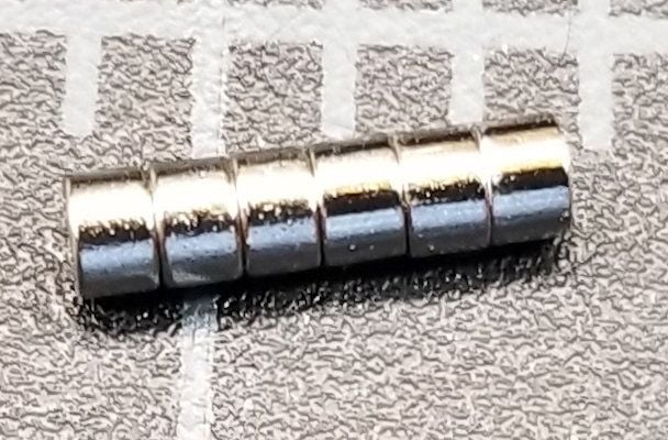
Remove the tiny magnets in the hub. The little magnets in the hub are simply press-fit. You can easily pop them out with a few firm taps with a punch/hex driver and hammer. See the pictures below. Since the brake disc has a floating movement range of only a fraction of a millimeter, if it does touch the core while freely spinning, it won't be hard enough or long enough to cause any appreciable friction. I've drawn a simple diagram that shows the wheel and brake assembly so you can better see the arrangement of components and visualize the problem and solution. After this simple 5 minute modification I have fully proportional brake function through the entire range of the controlling channel. Please note this is a non-destructive mod and you can reinstall the magnets in the hub if this does not resolve your issue.
I hope this helps others with the same issue.
Wheel/Brake Layout:
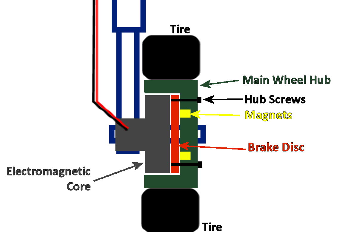
Here you can see how the brake disc floats on the hub screws.
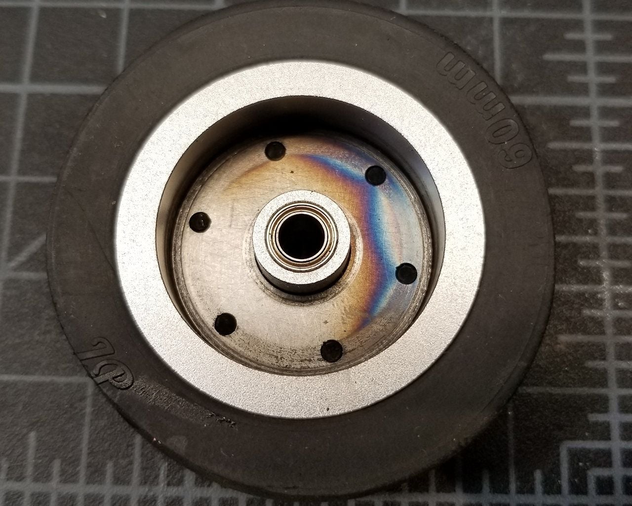
The location of the tiny-but-strong magnets in the hub:

The removed magnets:
Problem:
What seemed to be a great design didn't work out so well in practical application. There are two competing magnetic forces...the electromagnetic brake core and three tiny-but-strong magnets in the hub. The brake disc floats on the hub screws that protrude just enough to engage the disc. I believe the idea was that the three magnets in the hub will keep the disc away from the core to reduce random friction between the core and the disc. When the electromagnetic core activates, it overcomes the force of the hub magnets and pulls the disc against the core to cause the brake friction.
The implementation problem is that by the time the electromagnetic core generates a magnetic field strong enough to pull the disc away from the hub magnets, the core magnet strength is already so powerful that the wheel locks as soon as the disc engages the core.
Solution:
Remove the tiny magnets in the hub. The little magnets in the hub are simply press-fit. You can easily pop them out with a few firm taps with a punch/hex driver and hammer. See the pictures below. Since the brake disc has a floating movement range of only a fraction of a millimeter, if it does touch the core while freely spinning, it won't be hard enough or long enough to cause any appreciable friction. I've drawn a simple diagram that shows the wheel and brake assembly so you can better see the arrangement of components and visualize the problem and solution. After this simple 5 minute modification I have fully proportional brake function through the entire range of the controlling channel. Please note this is a non-destructive mod and you can reinstall the magnets in the hub if this does not resolve your issue.
I hope this helps others with the same issue.
Wheel/Brake Layout:
Here you can see how the brake disc floats on the hub screws.
The location of the tiny-but-strong magnets in the hub:
The removed magnets:
01-05-2019, 08:02 AM
#836
Just a note on this, see how there�s a tiny bit of axle showing on the gear leg side? On mine, one side was like that and the other side had no axle showing. When I did a brake test on mine the disc would come off the bolts and get wedged in between the bolts and the magnetic coil. Took me a little bit to figure it out because the other side worked fine. Finally I noticed the difference, loosened the setscrew on the axle and was able to push the whole assembly up tight against the gear leg. It only moved maybe 1.5 mm but it was enough to fix the problem. It came from the factory that way, just something to watch out for.
Last edited by camss69; 01-05-2019 at 10:00 AM.
01-05-2019, 10:48 AM
#837
Join Date: Jan 2011
Location: Benbrook, TX
Posts: 48
Likes: 0
Received 0 Likes
on
0 Posts
I did notice that when I was putting everything back together. Did it brake weird when this was happening? I pushed the axle far enough to close the gap but still spin freely.
01-05-2019, 11:41 AM
#839
Join Date: Jan 2011
Location: Benbrook, TX
Posts: 48
Likes: 0
Received 0 Likes
on
0 Posts
Yeah that makes sense from just looking at the design inside the hub. I will check for this today when I taxi it but I lined up the screws with the holes and then slid the axle in the gear leg trying not to disturb the alignment. It seems like slightly longer screws or shorter would do the trick. If the screws were short enough not to protrude past the hub the disc would just spin freely and if they were a touch longer the alignment of the disc wouldn't be as big of an issue. When I tested mine last night the brakes appeared to release fine but that was a very short roll.
I'm down to battery placement for CG and removal purposes now. I put my ECU battery just forward of the main tank on the left side behind my landing gear controller. My receiver batteries are the issue as they have very long wires and I seem to be getting 193mm or so with one batt on the tray above the NLG and one on the radio tray. I will be shooting for 195mm after reading this entire thread a few times. If I need to go farther aft then so be it. As long as my measurements are correct I should be good to go.
Here in about an hour or so I will run the engine for the first time and taxi it.
Last edited by firehawkzach; 01-05-2019 at 11:44 AM.
01-05-2019, 03:23 PM
#840
Join Date: Jan 2011
Location: Benbrook, TX
Posts: 48
Likes: 0
Received 0 Likes
on
0 Posts
Initial engine run and taxi went flawless. First start the engine idled at 57k rpms and ran perfect all three starts and full power runs. My brakes need some tweaking and at idle the jet moves without them. It consumes fuel pretty fast so I will start flight times at 6 minutes.
01-05-2019, 03:53 PM
#841

Initial engine run and taxi went flawless. First start the engine idled at 57k rpms and ran perfect all three starts and full power runs. My brakes need some tweaking and at idle the jet moves without them. It consumes fuel pretty fast so I will start flight times at 6 minutes.
01-06-2019, 07:02 AM
#843
01-06-2019, 01:34 PM
#845
Join Date: Jan 2011
Location: Benbrook, TX
Posts: 48
Likes: 0
Received 0 Likes
on
0 Posts
Not to get too much off topic here as this is the mini T-1 thread but this is my first set of LiFe batteries and it would seem after one taxi test of about ten minutes my battery capacity check is showing 43% remaining at 3.31v on both batteries. I have read that it's difficult to determine capacity remaining by a battery checker and the only way to know is mah replenished through charging. My little charger that works for LiFe batteries doesn't provide that detail and I have not attempted to use my power lab 6 to charge a LiFe battery. There are presets in the charger for A123 batteries but not LiFe. Anyone have any insight that could help me here. I really don't want to charge after every flight. I'm running my two Kingtech 2100mah LiFe batteries to the batshare and running servos and gear/brakes from it.
The high speed taxi went well today although my left brake disc is definitely catching the screws as it keeps pulling left when I get on the brakes. I probably need to increase the RH brake output on the controller but I will have to play with it. I will reset the disc and position on the axle after my trip this week. Even though she runs and taxis well I think I still have a bit of work left before its ready for the maiden.
Thanks for all your help guys!
Zach

 01-06-2019, 03:47 PM
#849
01-06-2019, 03:51 PM
#850
I would not charge them in parallel unless you have a multi-channel charger that can charge multiple packs independently. That�s just my opinion though. I have a couple of those Hitec 4 channel chargers, I can charge both flight batteries independently as well as the turbine battery all at the same time. I make it habit to top off batteries before each flight and usually bring more than one jet so I can fly one while the other is charging.