


F 100 from "Mirce models" wooden kit
 06-26-2018, 03:42 AM
#26

My Feedback: (24)
To play on the above comments -
You have a very talented CAD operator. If you designed the above in Fusion 360 or Inventor, or other similar parametric modelling tool, you could simply scale it down (theoretically) and all your CAM output SHOULD follow. however I would guess actually putting it into production would be a different story. Am I even close in this assumption?
So, what software are you using? I'm new at Inventor myself and it looks like it's going to be discontinued in the near future in favor of Fusion and am re-considering where I put my study time.
The kit is absolutely hypnotic in the way it's fitting together perfectly! Just love it.
 06-26-2018, 08:36 AM
#27
Thread Starter
Thank you for comments.
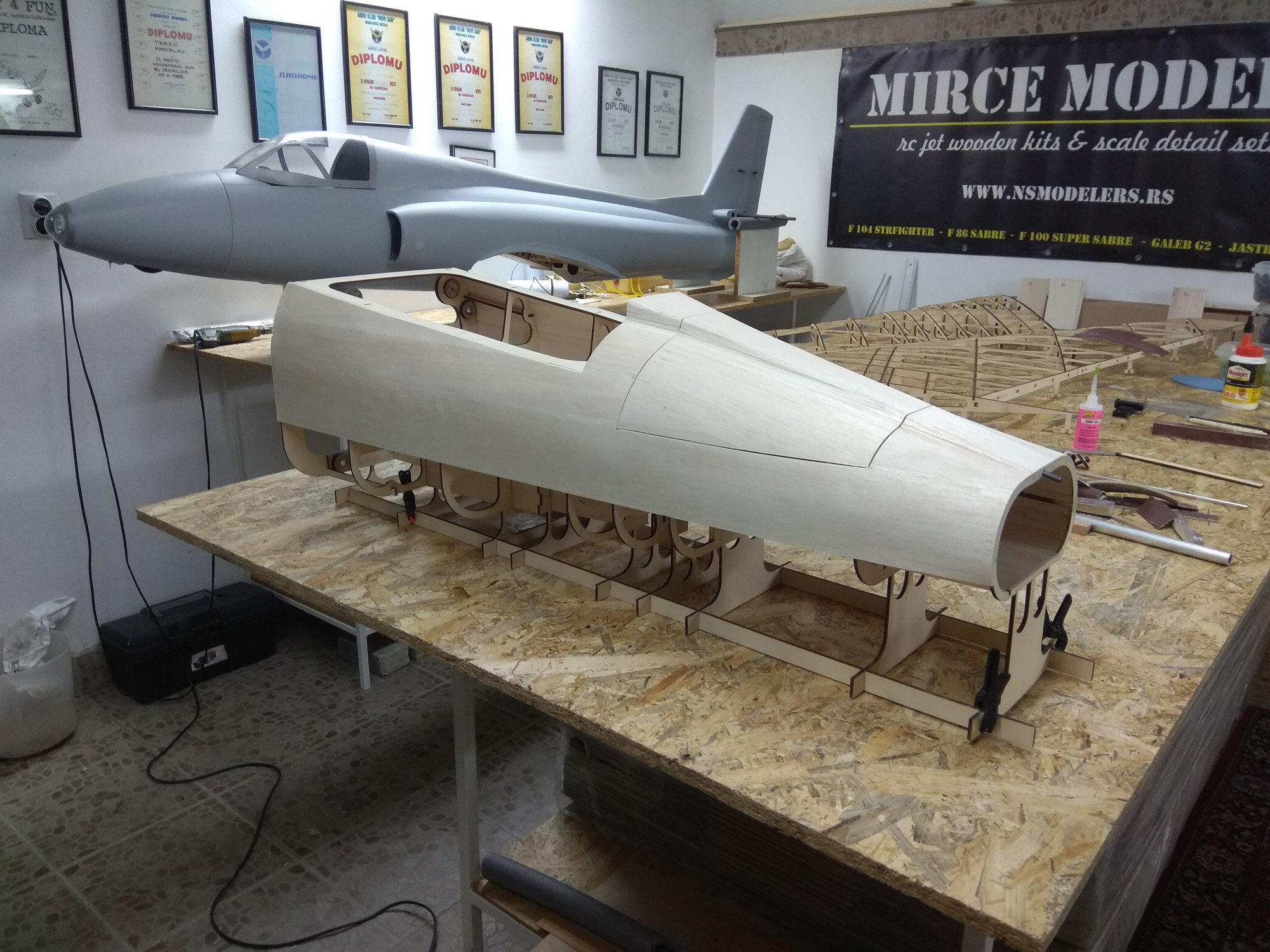
The idea of "Mirce models" is that the market offers a large jet wooden kit models.
3D drawings are made in the Catia program. Since model construction is first drawn, and then parts cut into a laser cut machine, everything fits perfectly.
Theoretically it is not a problem to reduce the model by for example 25%, but then you need to re-draw some parts, make a new cabin vacuum tool, aluminum tubes will not fit, etc...
The thrust tube can be ordered from the manufacturer in your area.
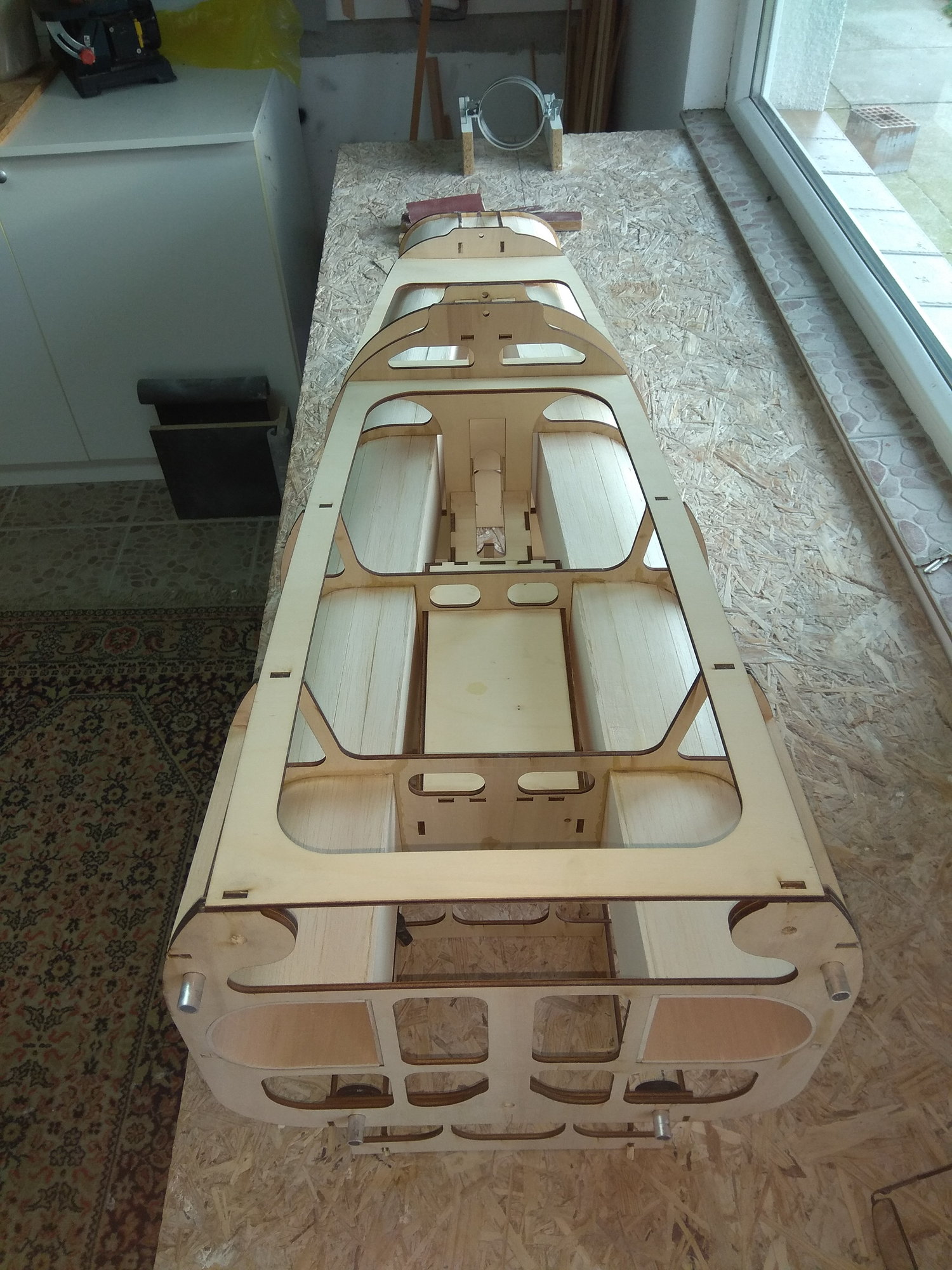
Model have full inlet tunnel.
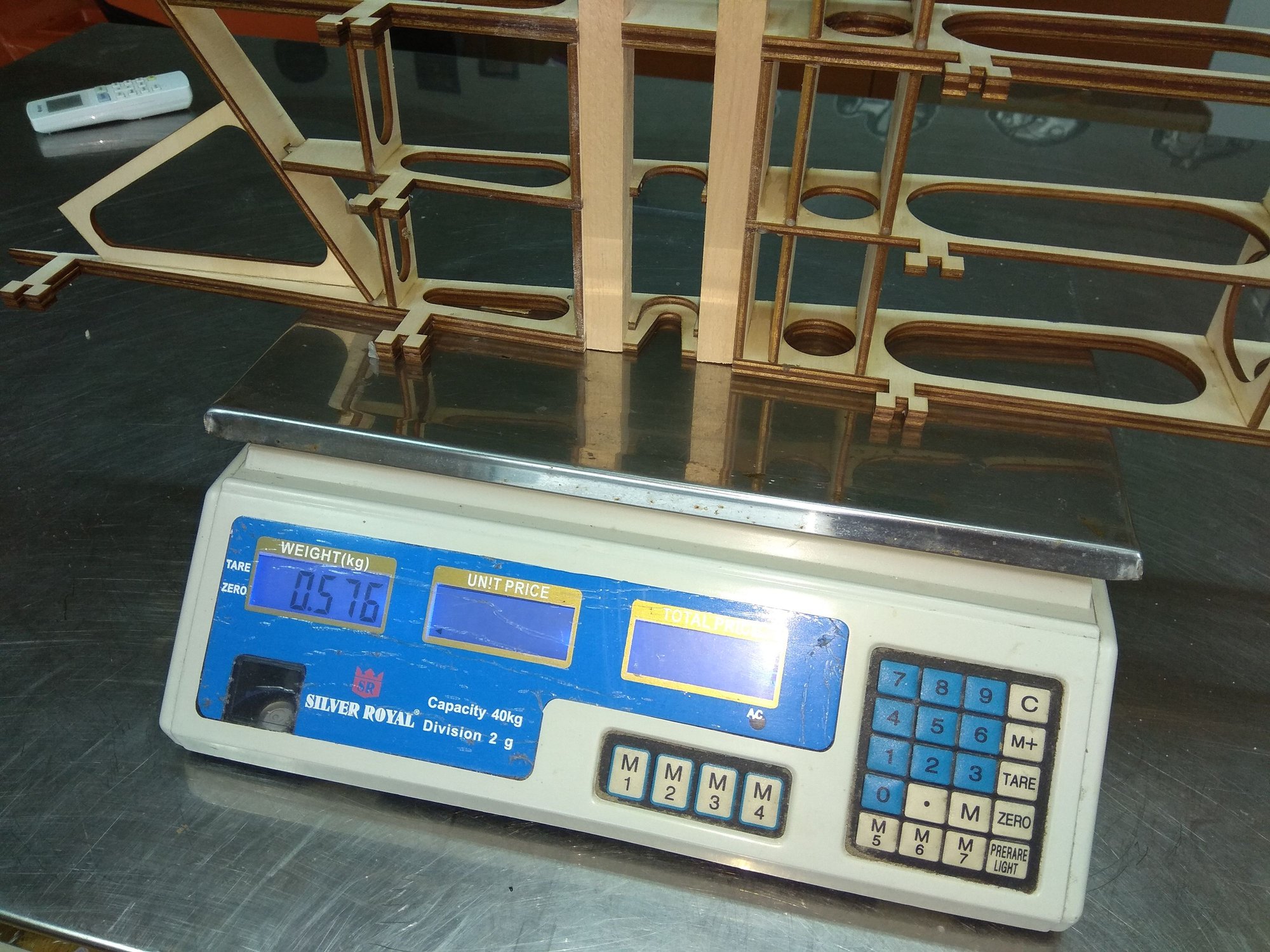
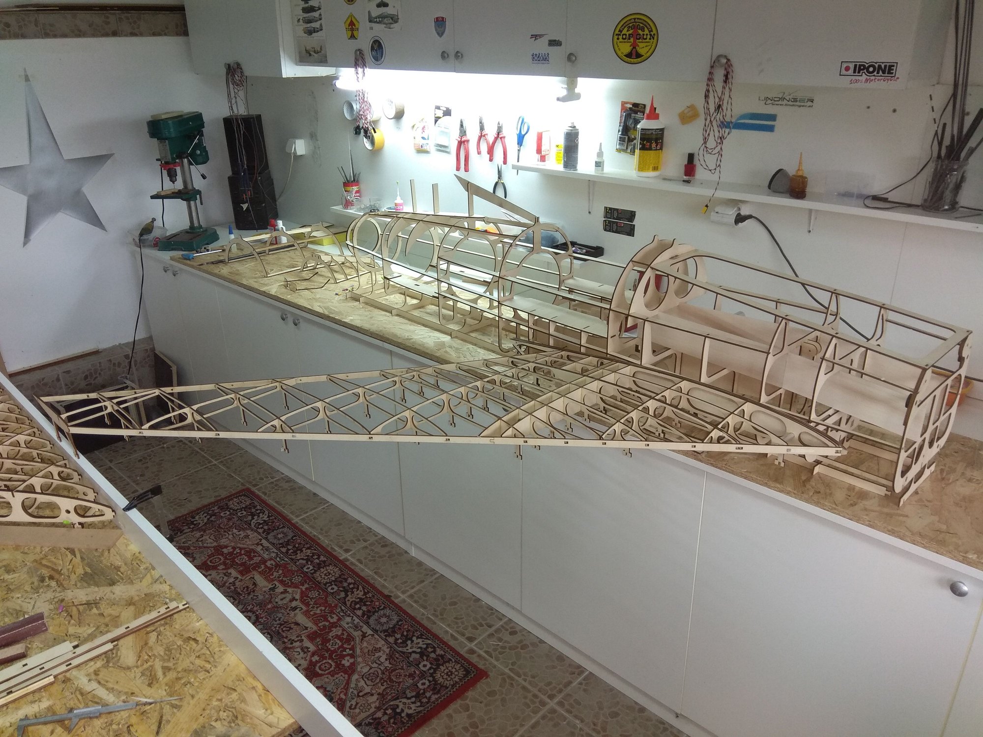
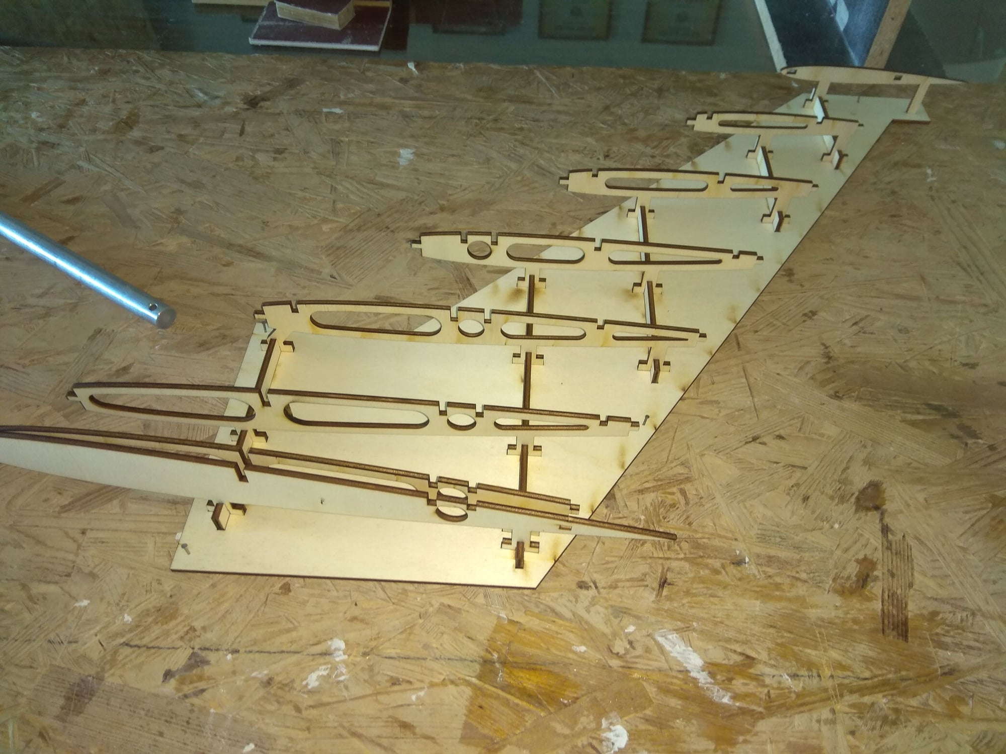
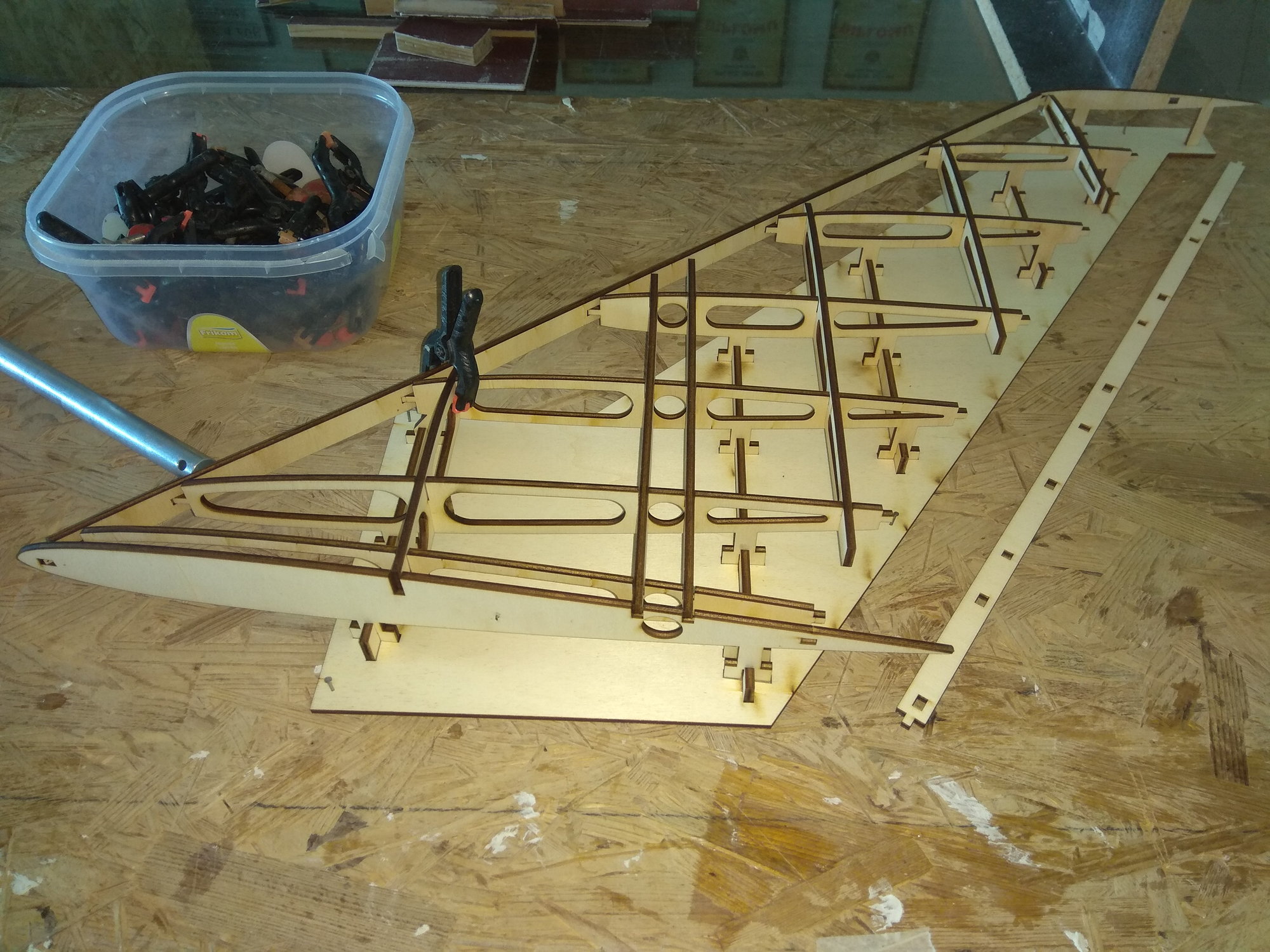
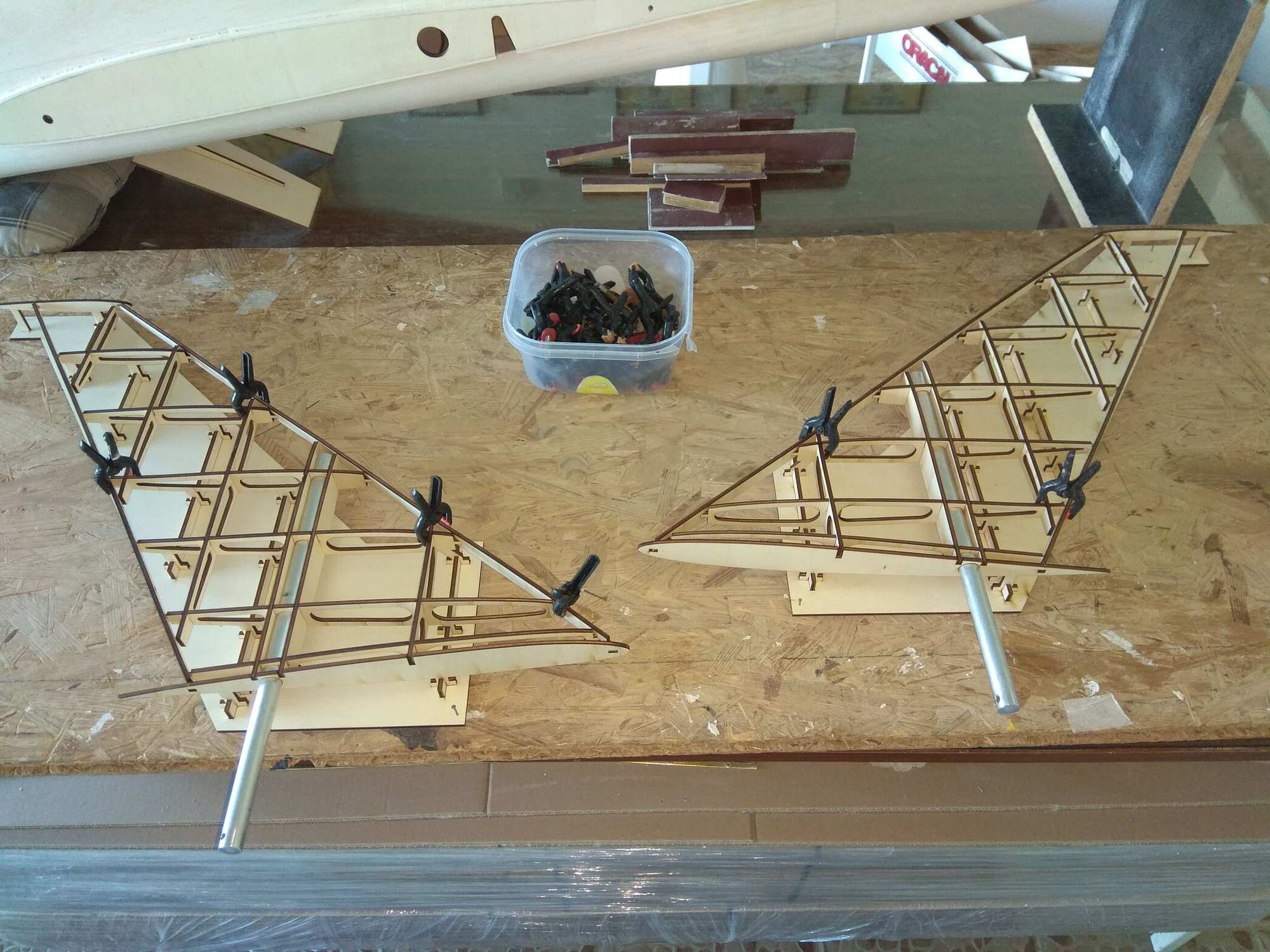
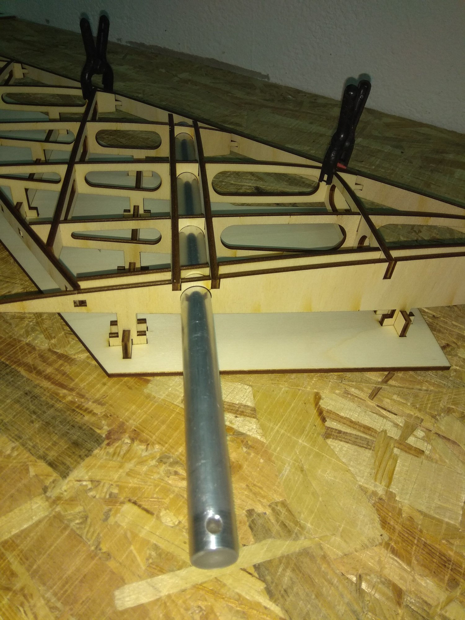
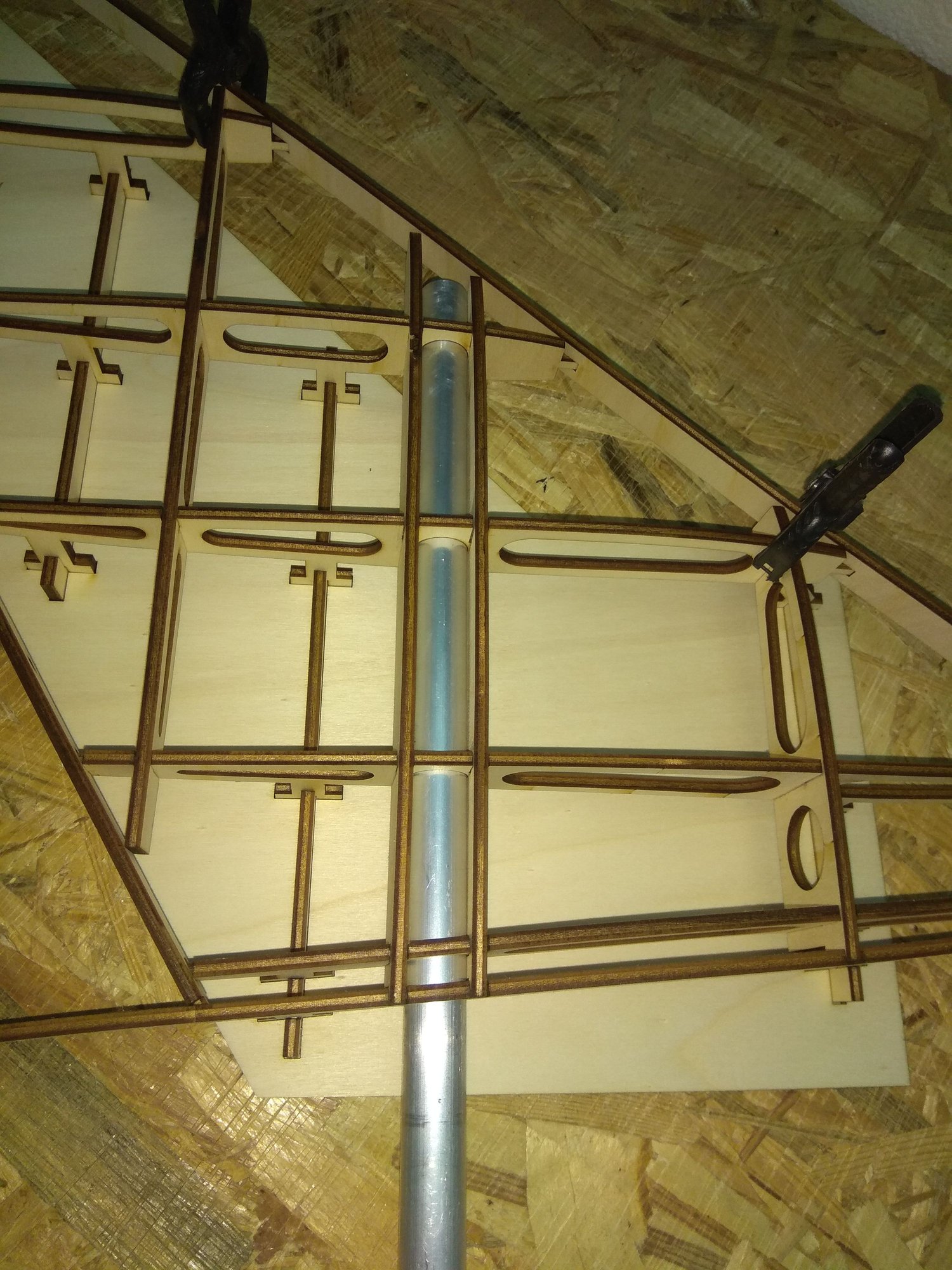
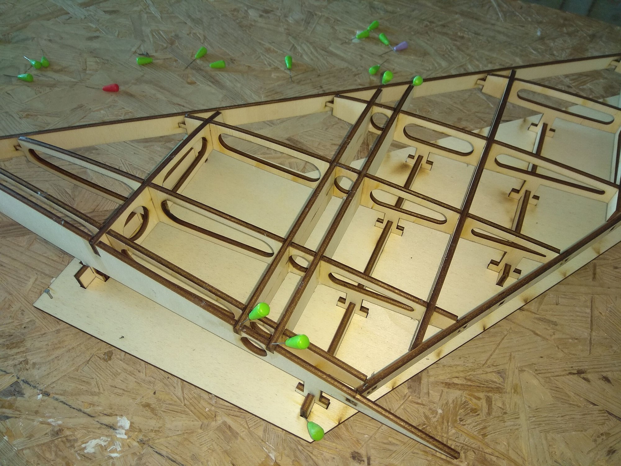
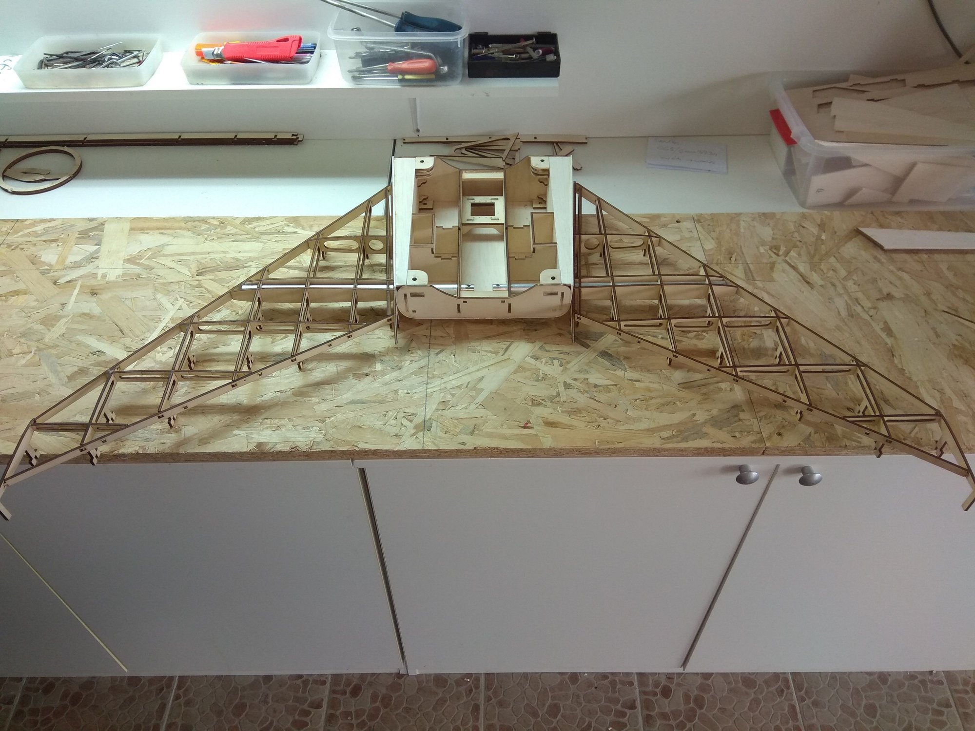
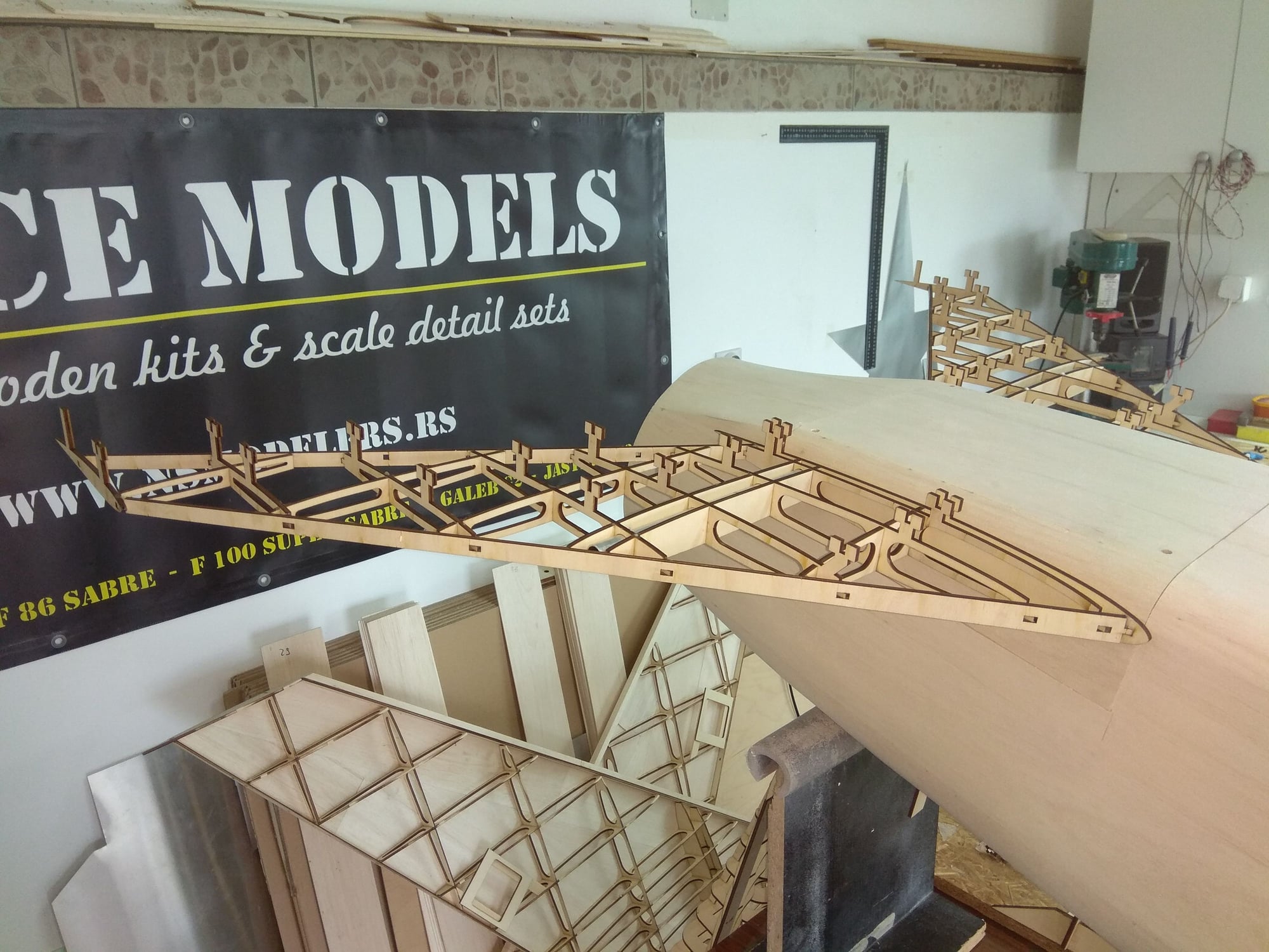
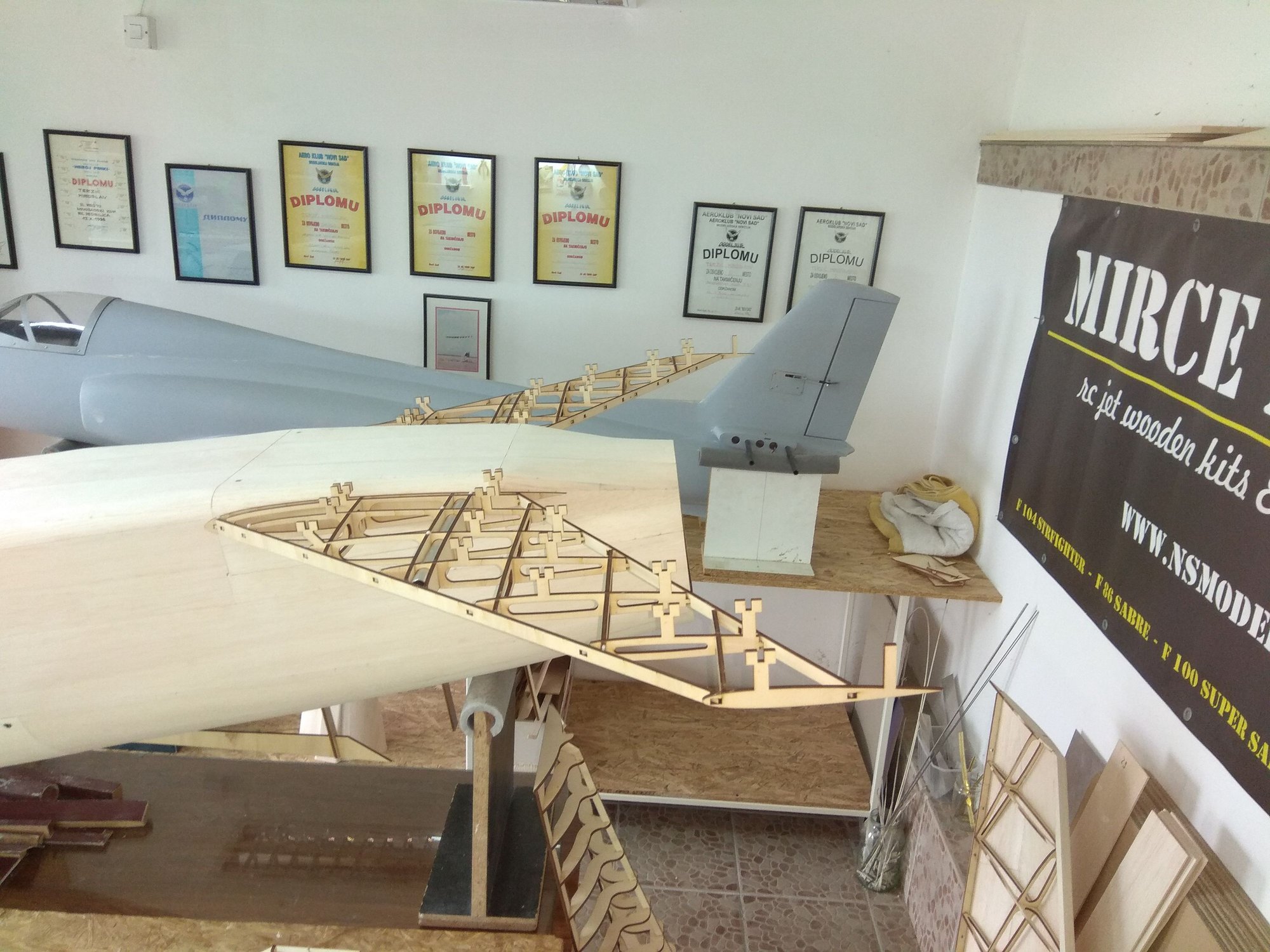
I measure wing in this phase, not bad for so huge construction...

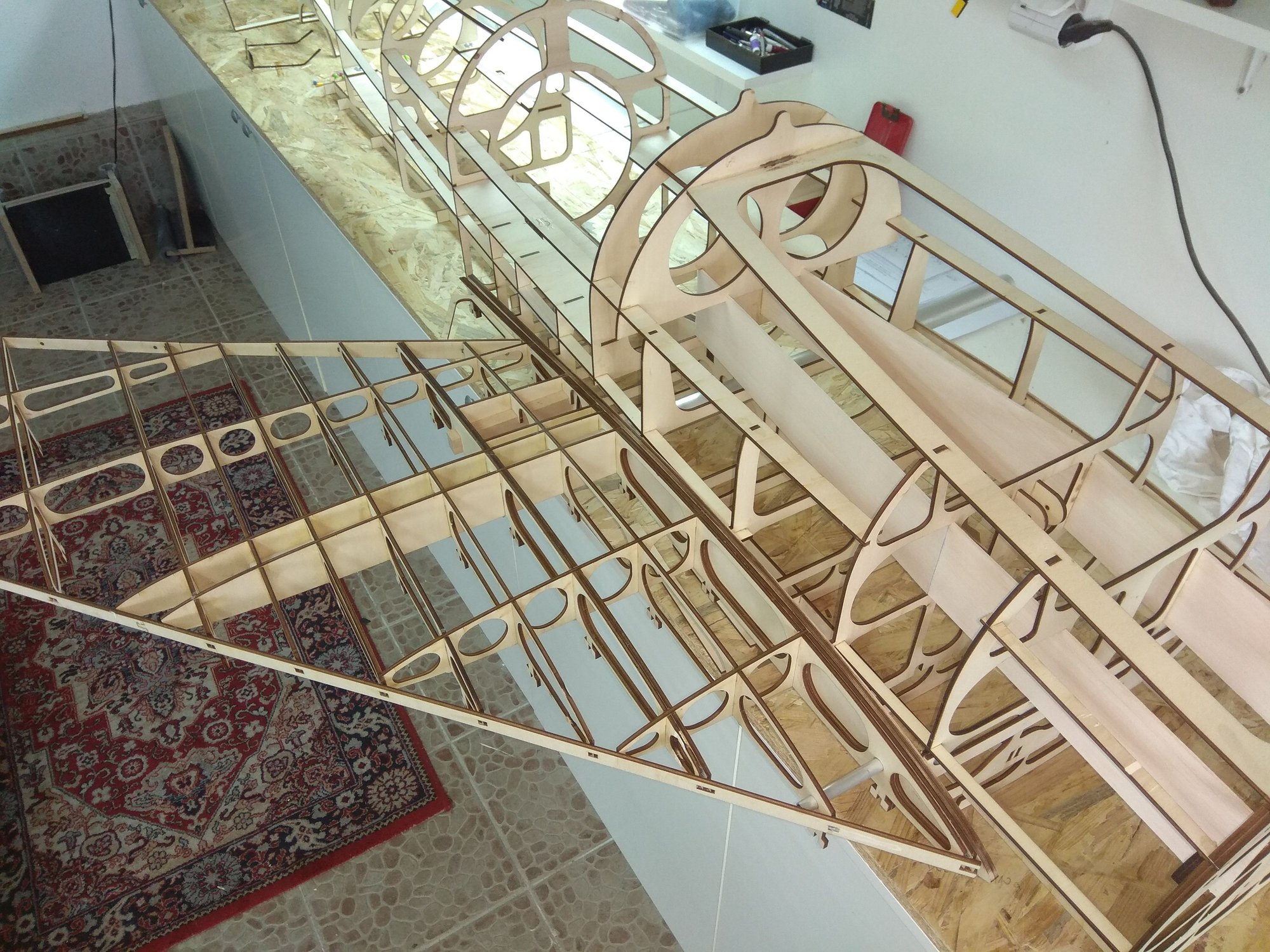
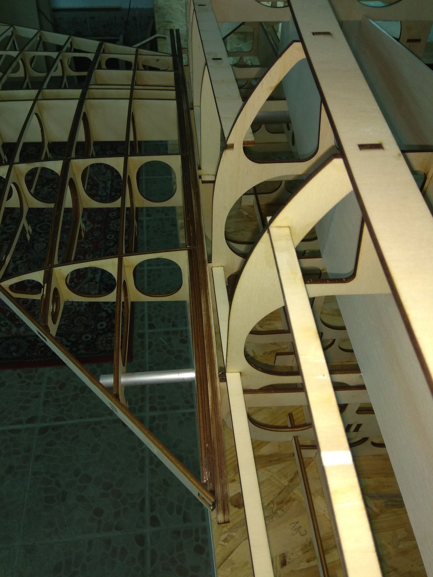
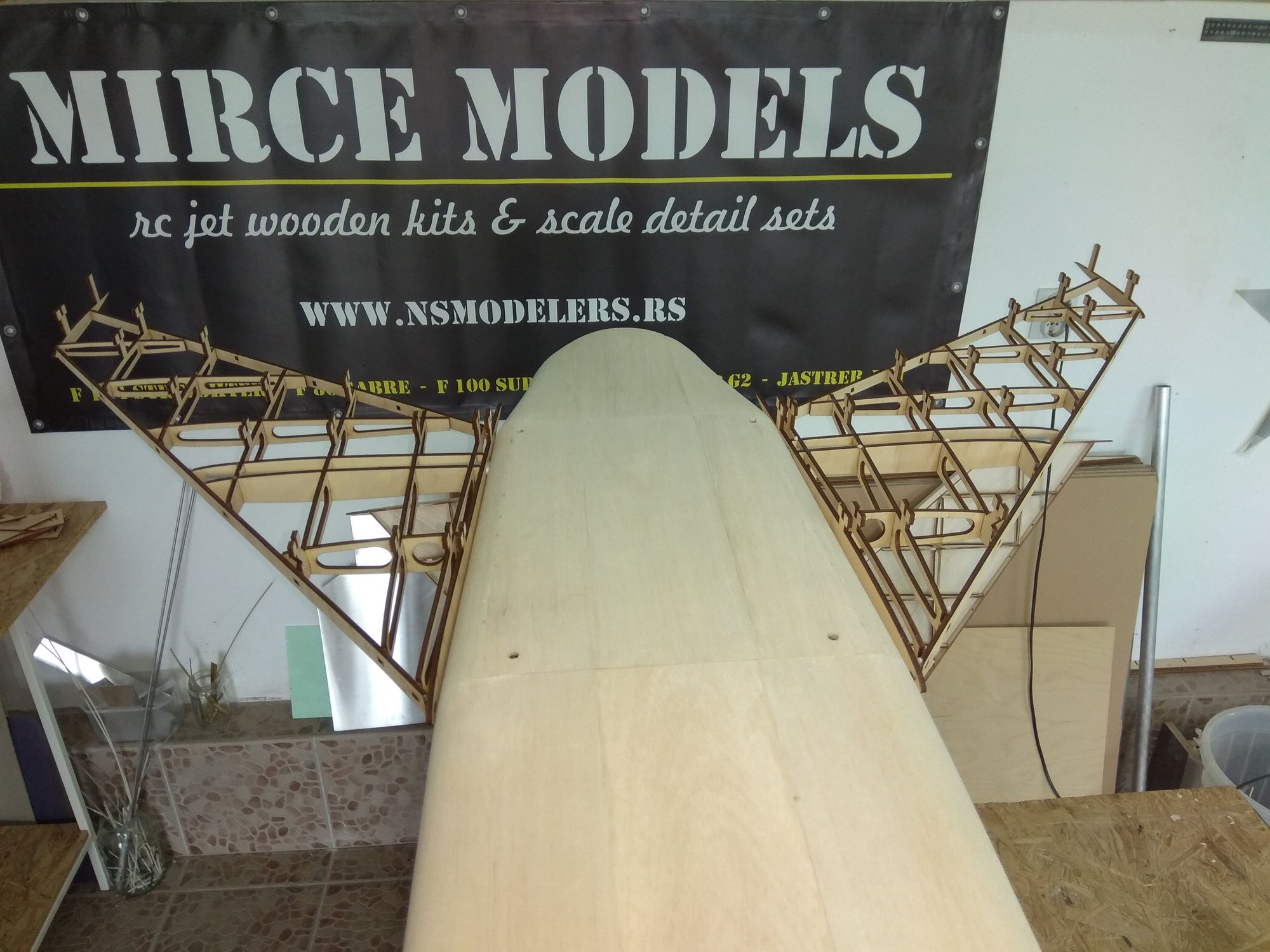
And few photos how wing fit on fuselage...

New photos soon...
The idea of "Mirce models" is that the market offers a large jet wooden kit models.
3D drawings are made in the Catia program. Since model construction is first drawn, and then parts cut into a laser cut machine, everything fits perfectly.
Theoretically it is not a problem to reduce the model by for example 25%, but then you need to re-draw some parts, make a new cabin vacuum tool, aluminum tubes will not fit, etc...
The thrust tube can be ordered from the manufacturer in your area.
Model have full inlet tunnel.
I measure wing in this phase, not bad for so huge construction...
And few photos how wing fit on fuselage...
New photos soon...
Last edited by mirce; 06-26-2018 at 08:47 AM.
06-26-2018, 12:54 PM
#29
Thread Starter
Hello Fred, kit is available, you can order it.
More details you see on my web site, F 100 page: Damiano & Mirce models F 100 Super Sabre - NS Modelers
or on my Facebook page: https://www.facebook.com/profile.php?id=100010159931781
For first three buyers I give 20% discount on wooden kit, two kits are sold until now. So you can be third...
Please send me e-mail for more information: [email protected]
Mirce
06-28-2018, 01:46 PM
#30
Thread Starter
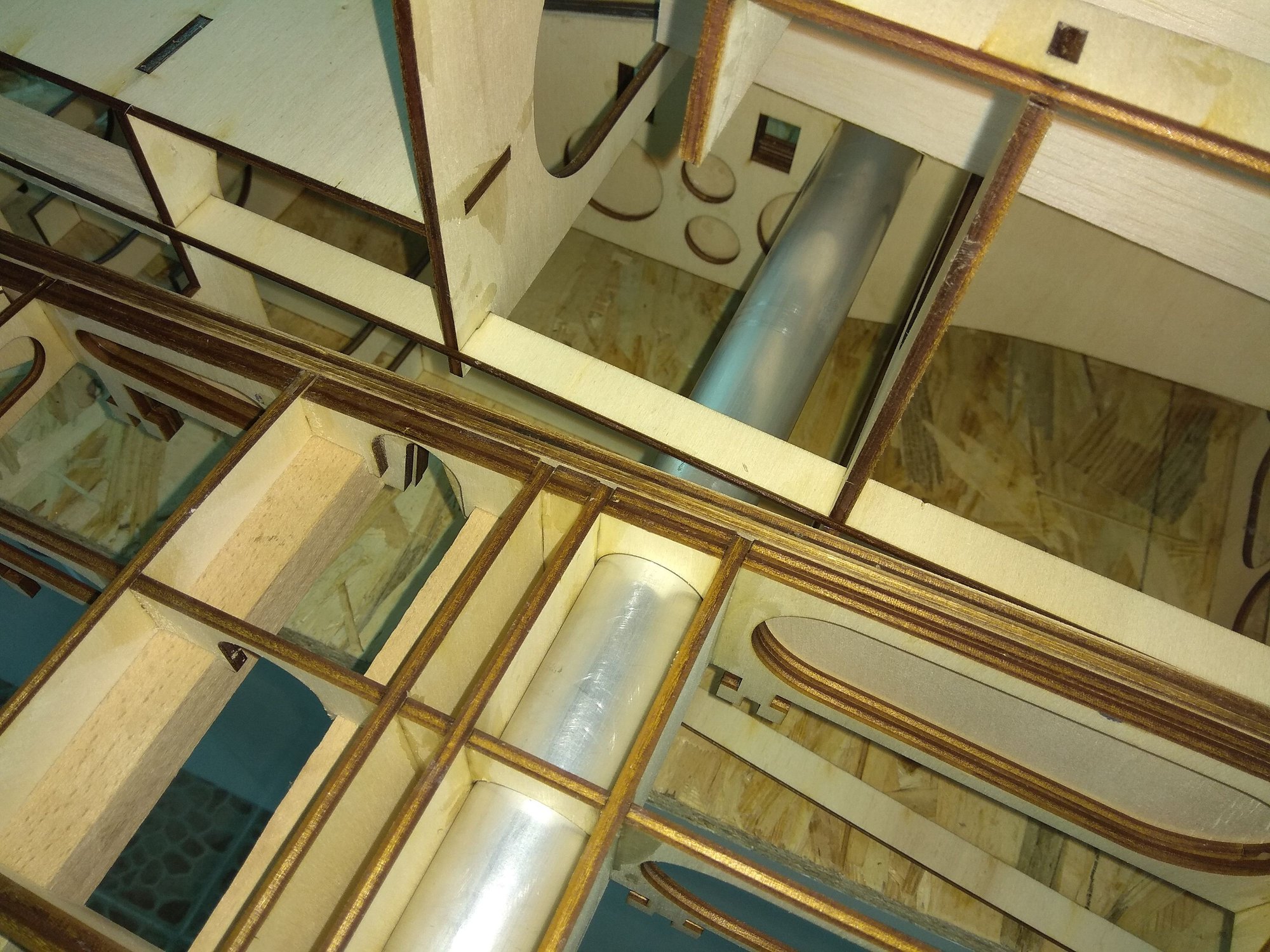
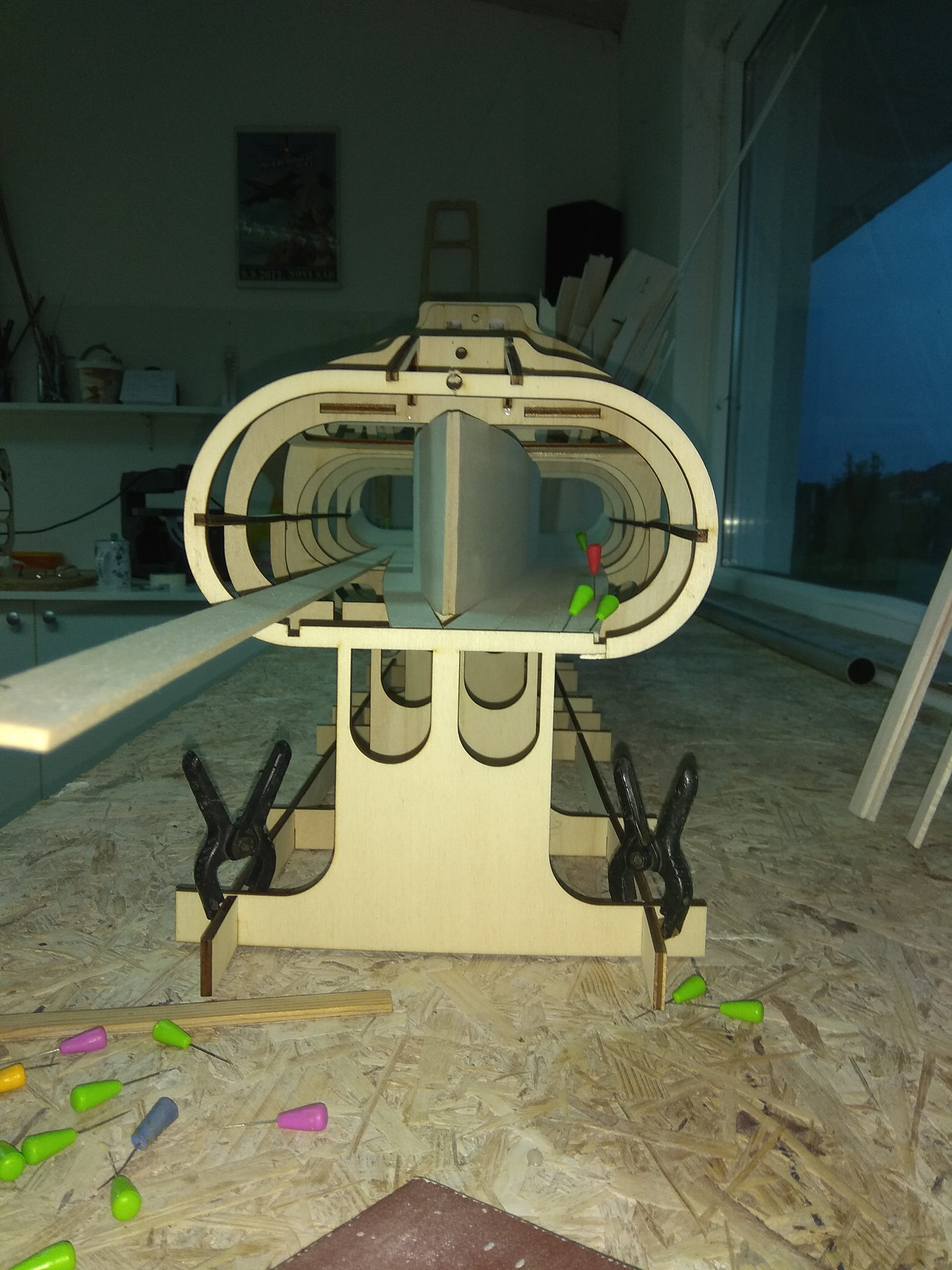
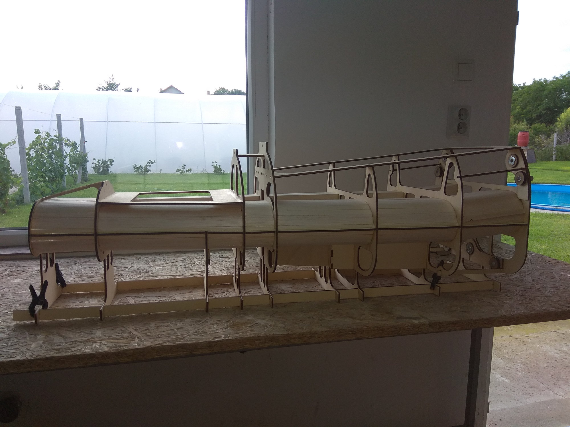
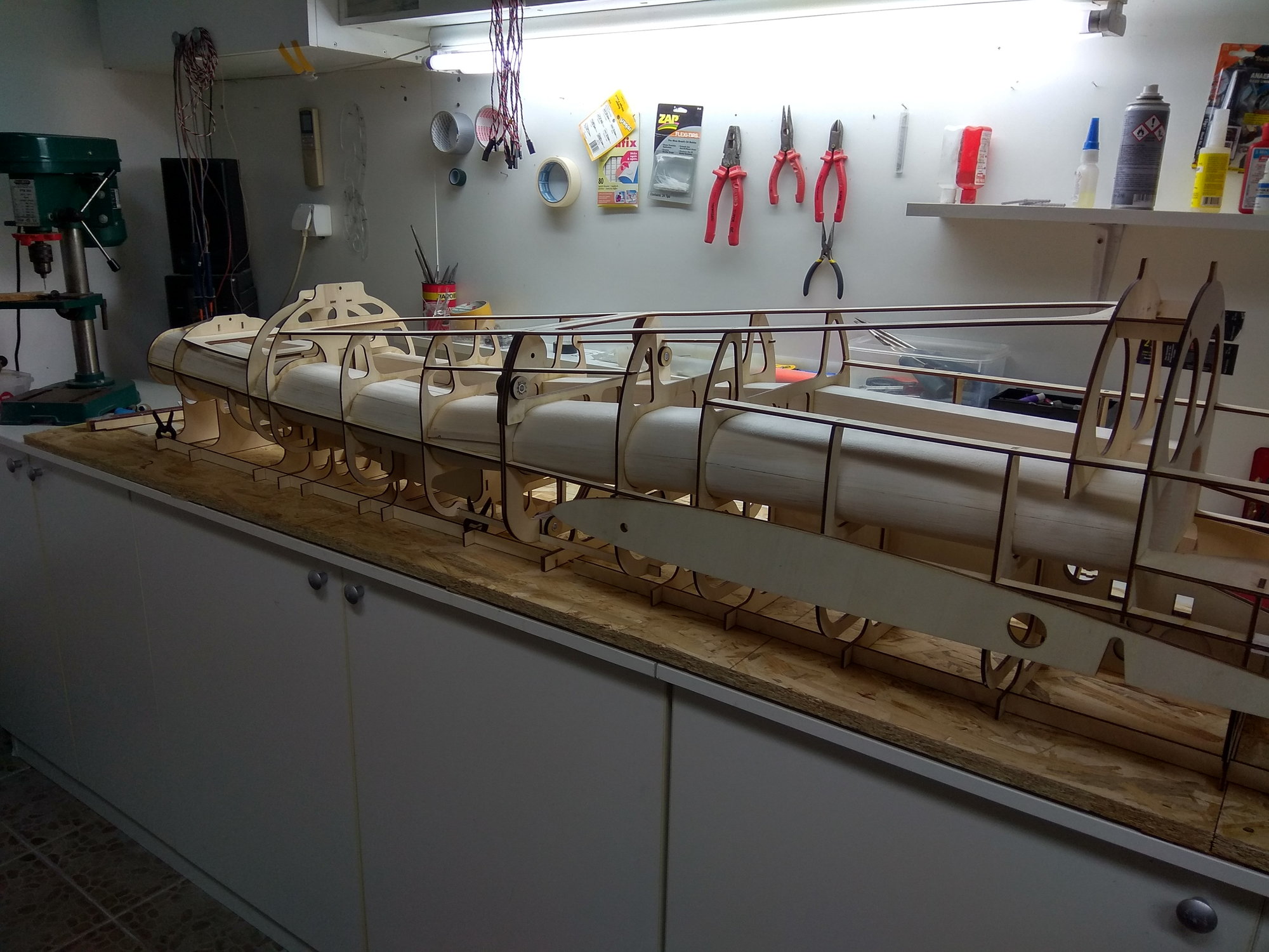
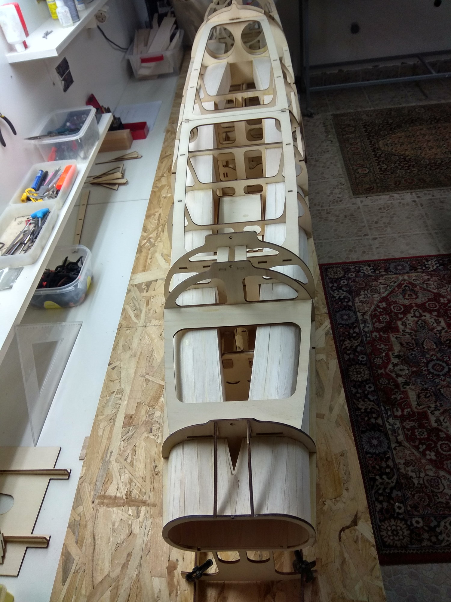
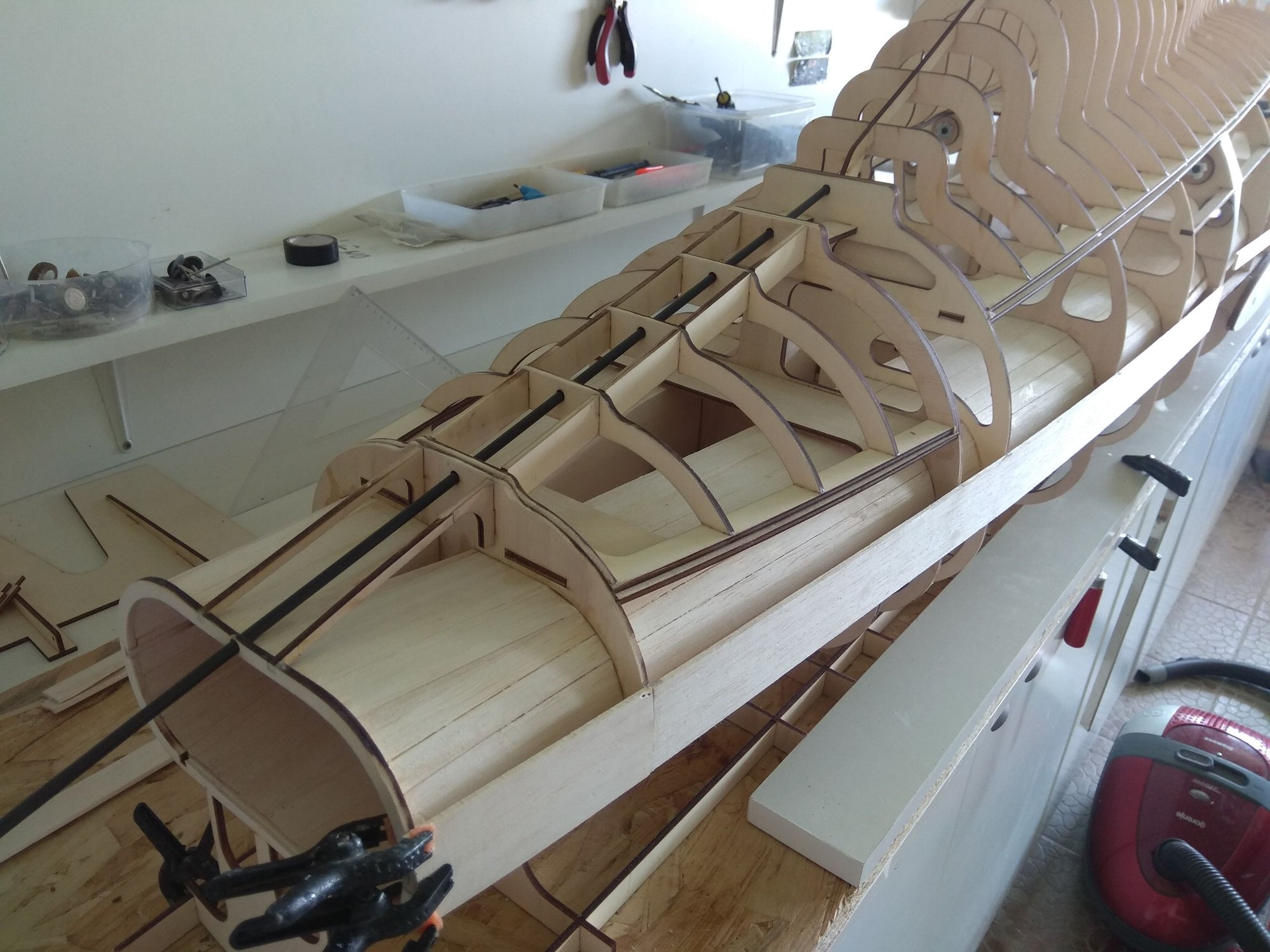
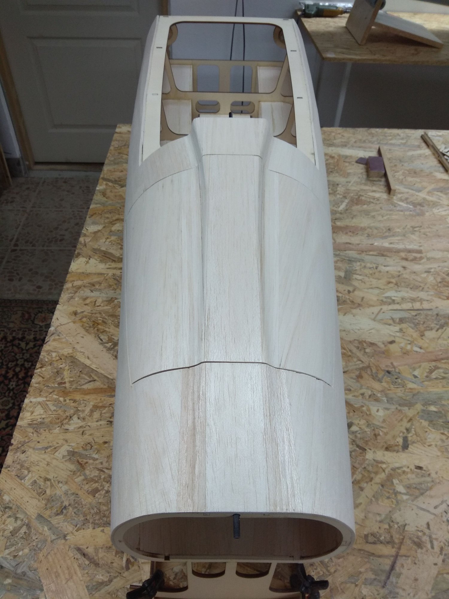
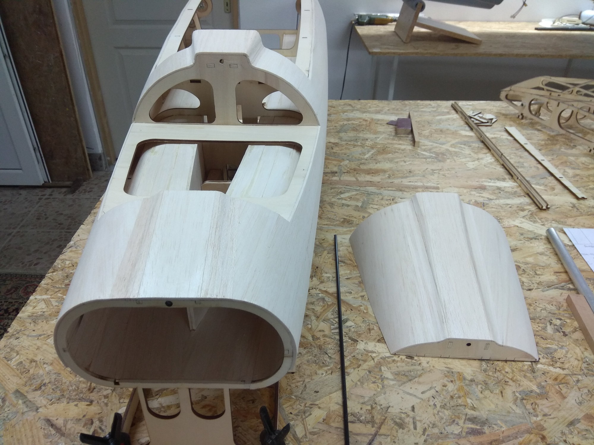
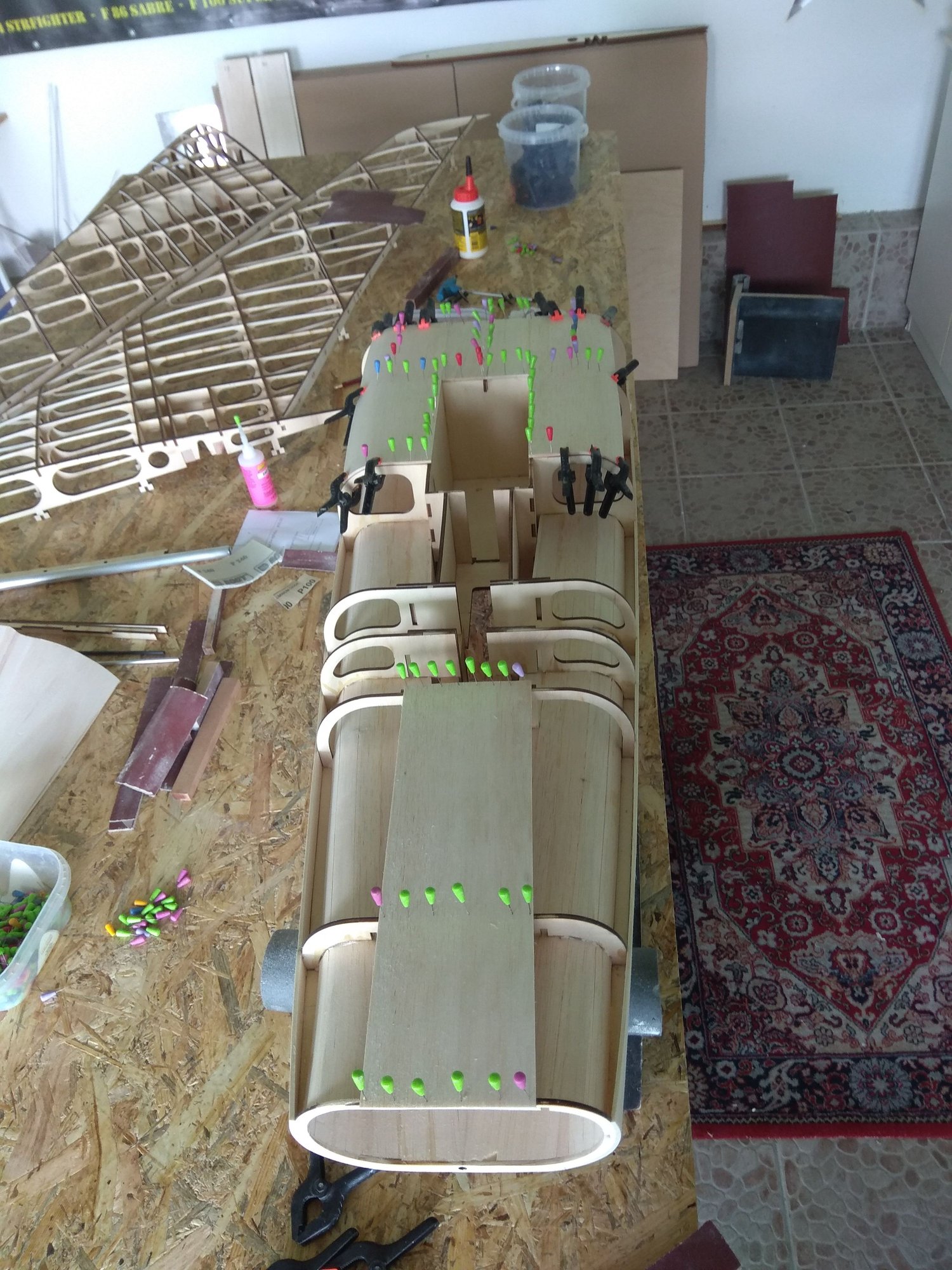
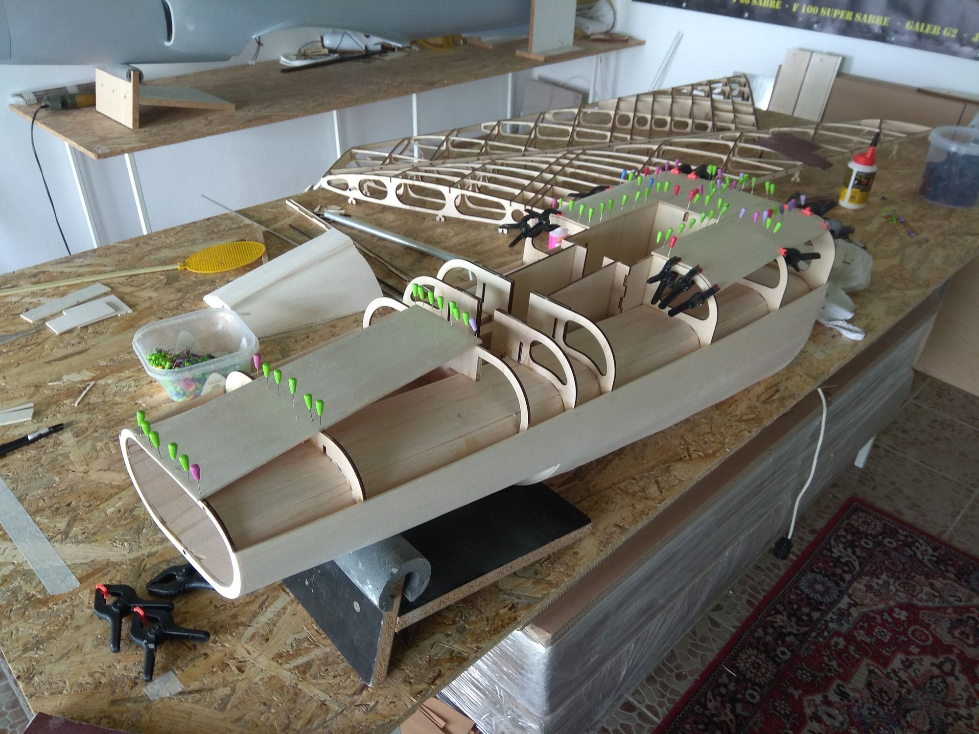
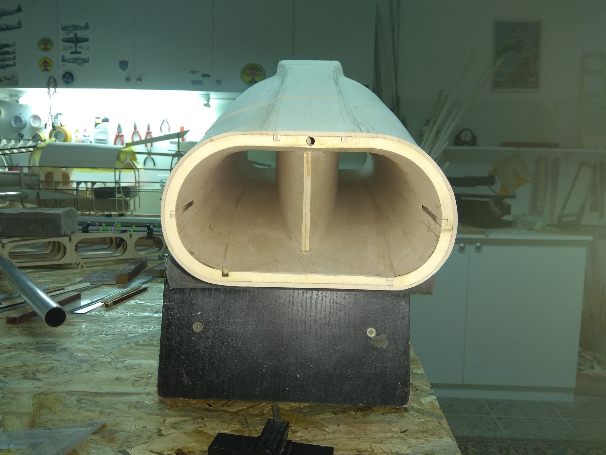
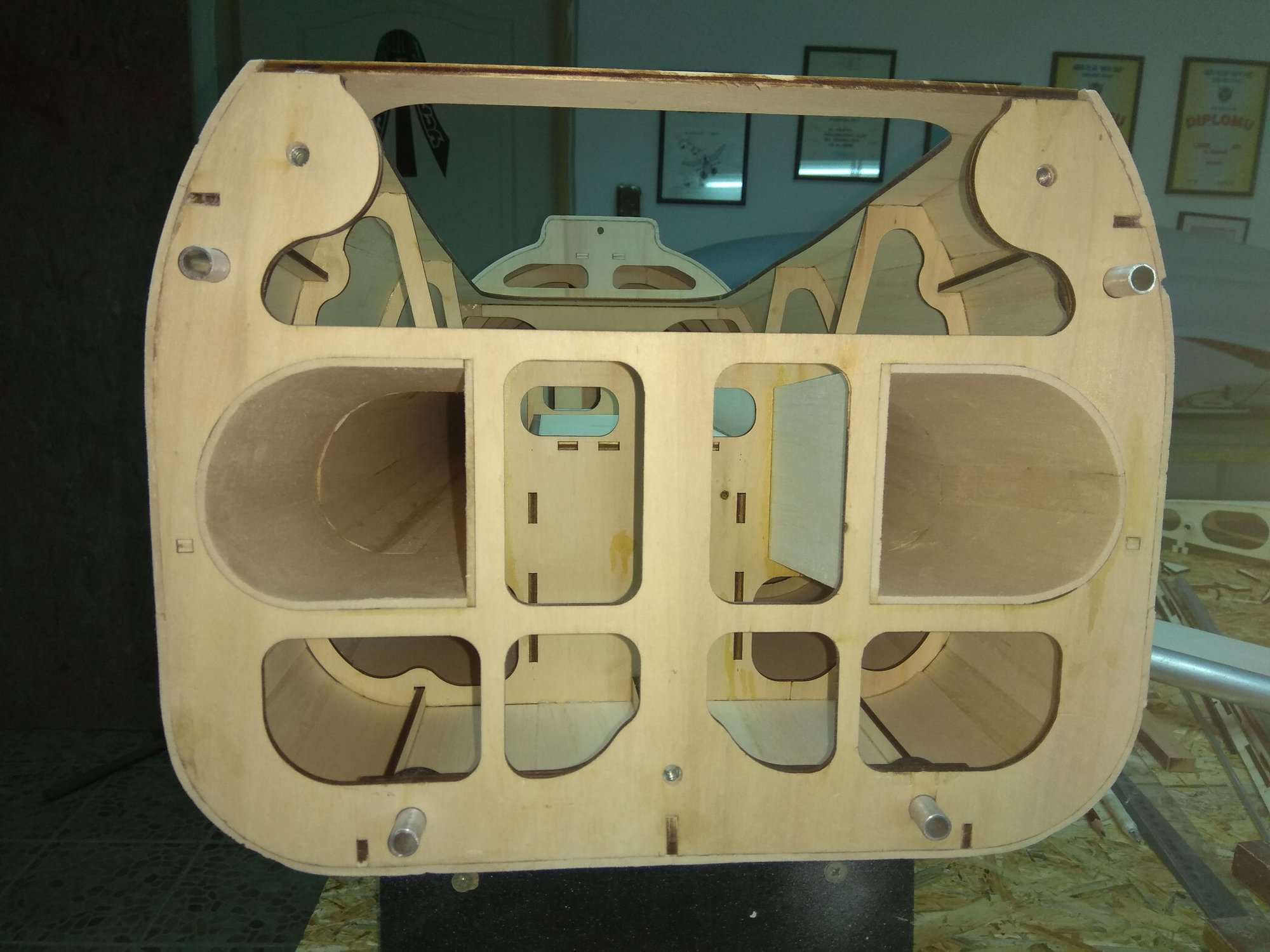
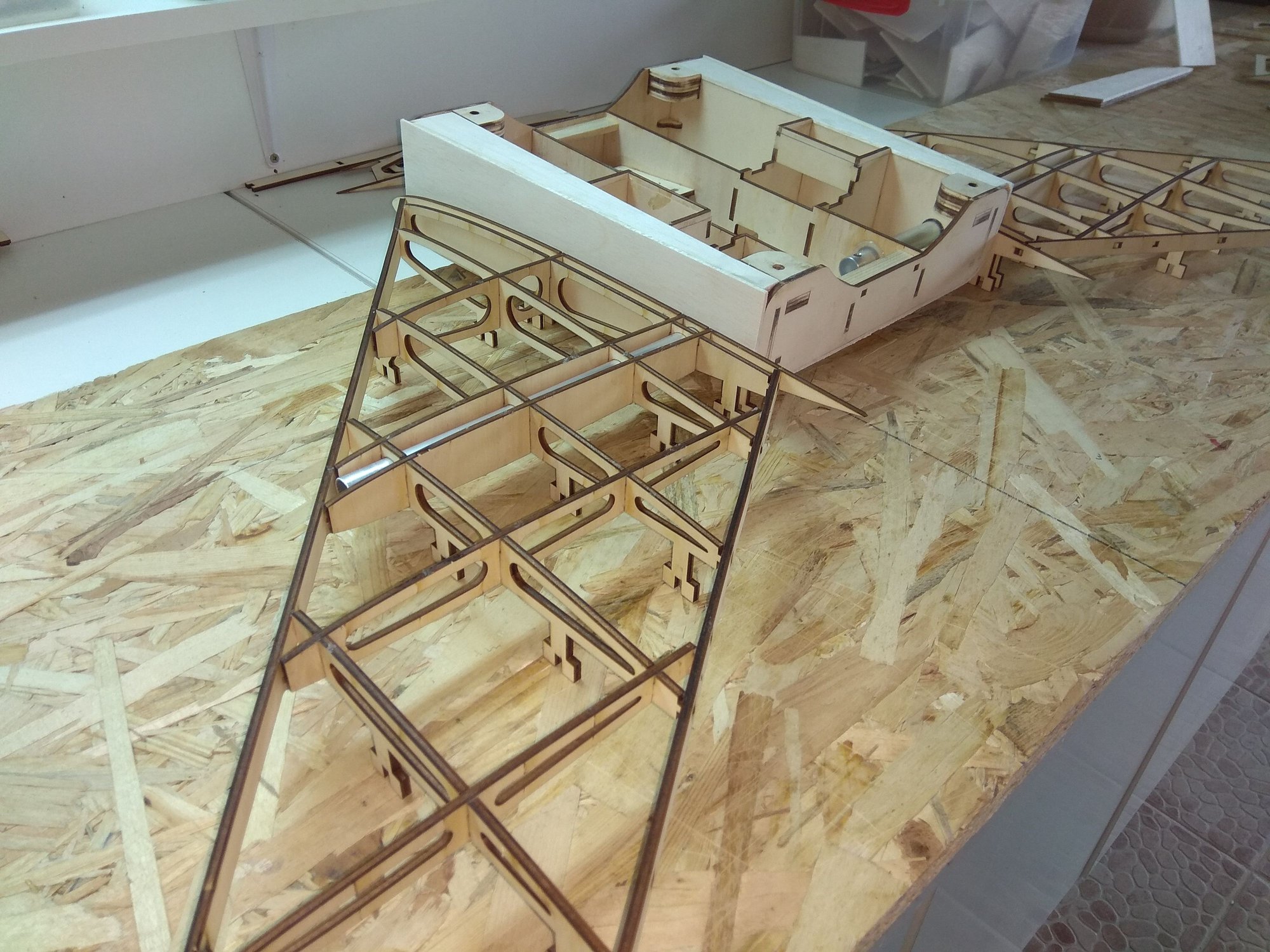
In the fuselage there are channels that bring the air directly to the turbine.
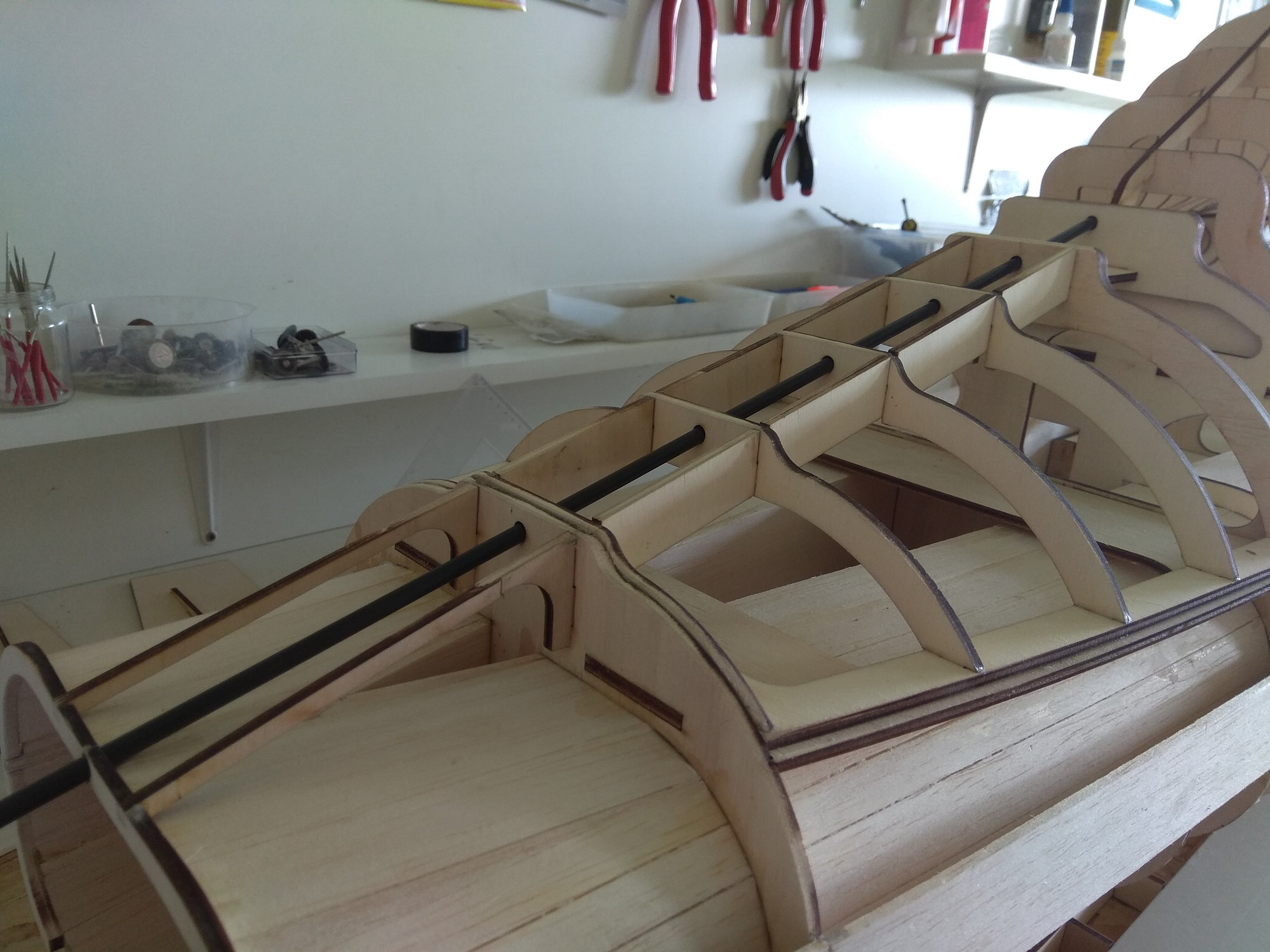
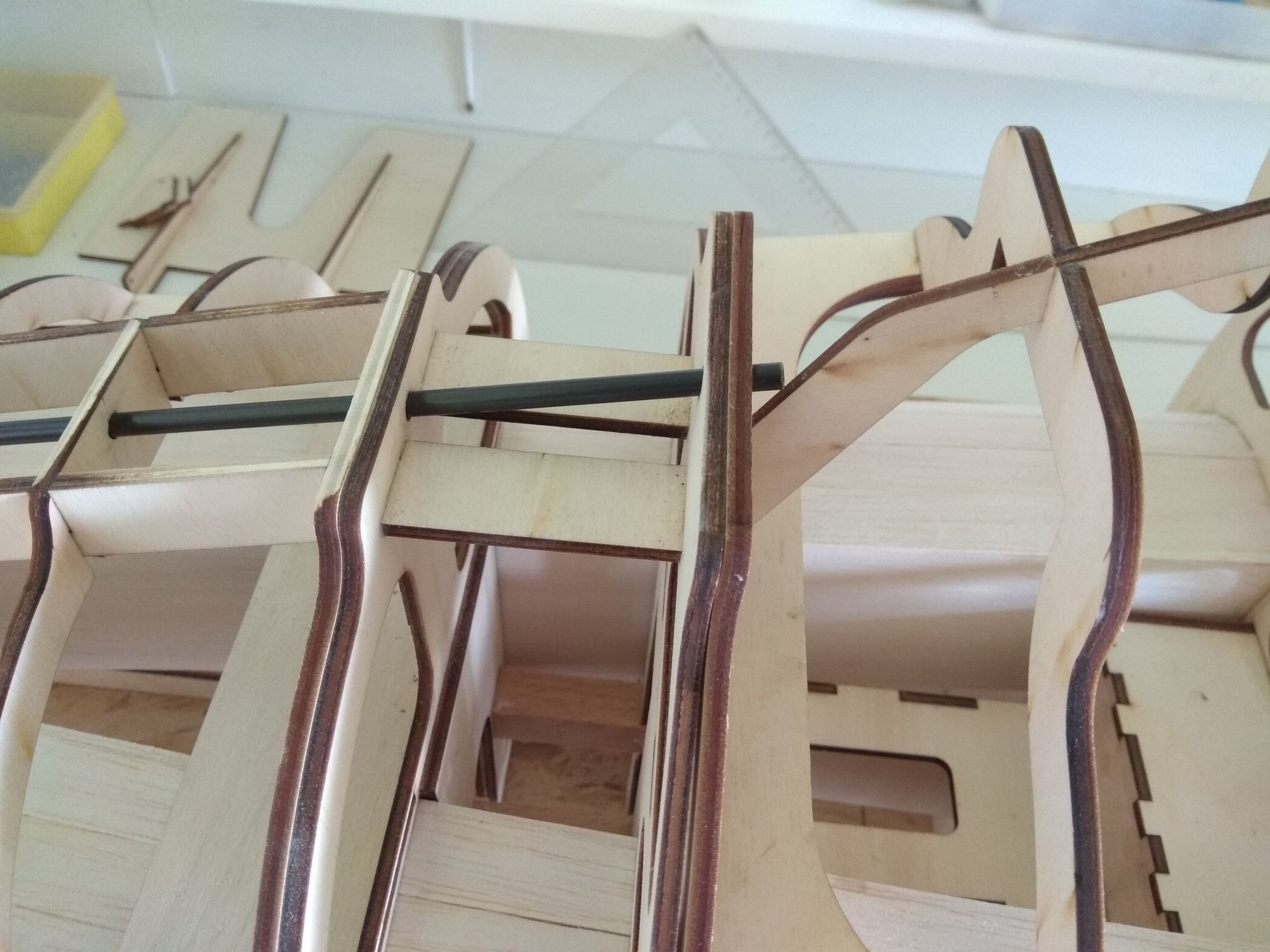
In the front fuselage part, the channels have a mild curve, so they have to be made of balsa strips that are placed next to each other.
I used CA glue for this process.


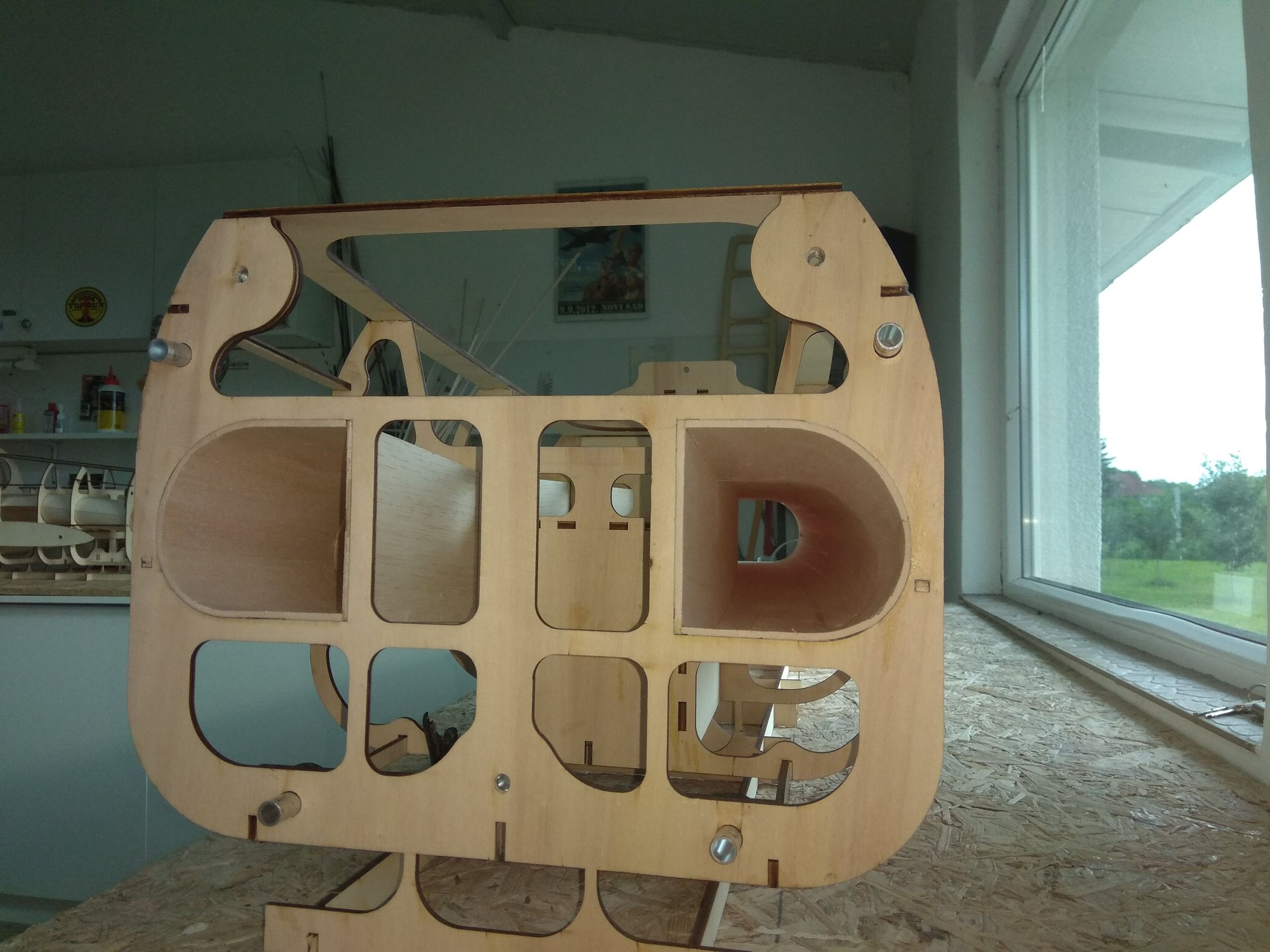
The channel in the rear fuselage section was a bit easier to make, because the shape is correct, only in one place it has a slight changeover.
To make balsa easier to bend I used hot water and I used a white carpentry adhesive for gluing.
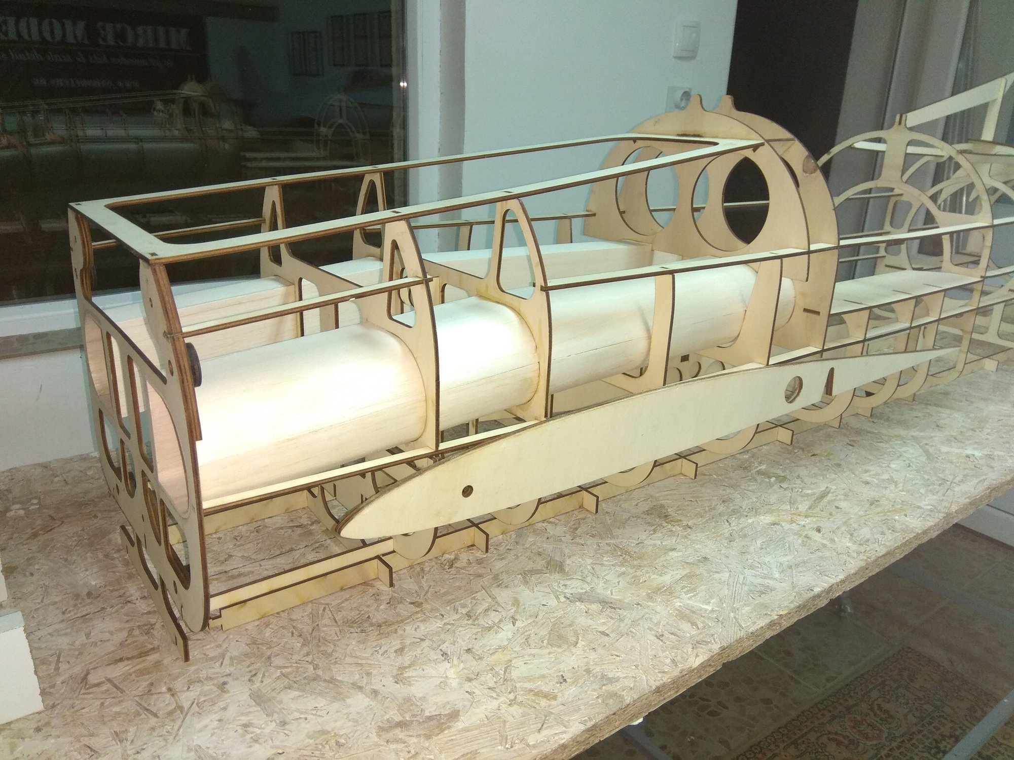

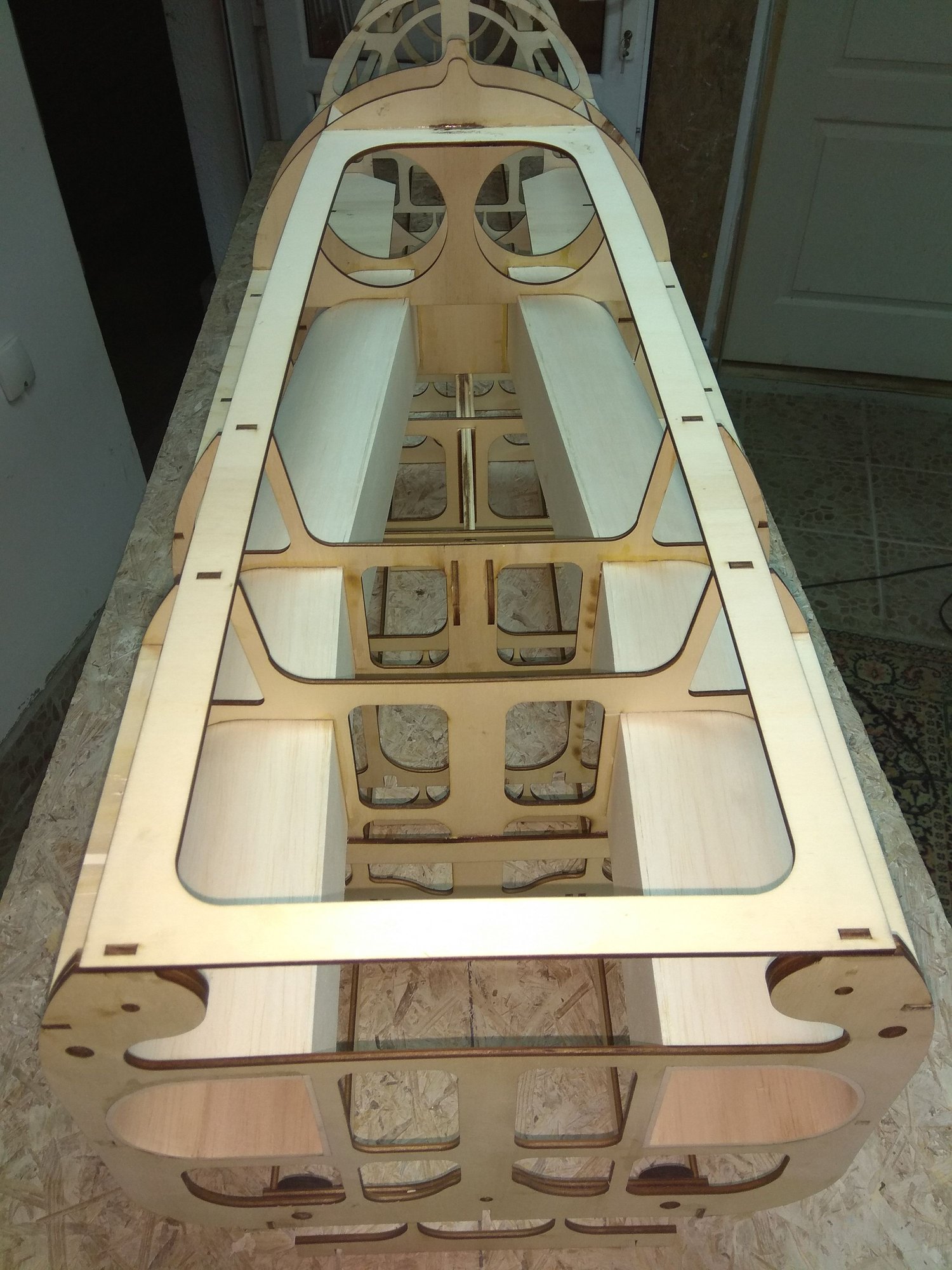
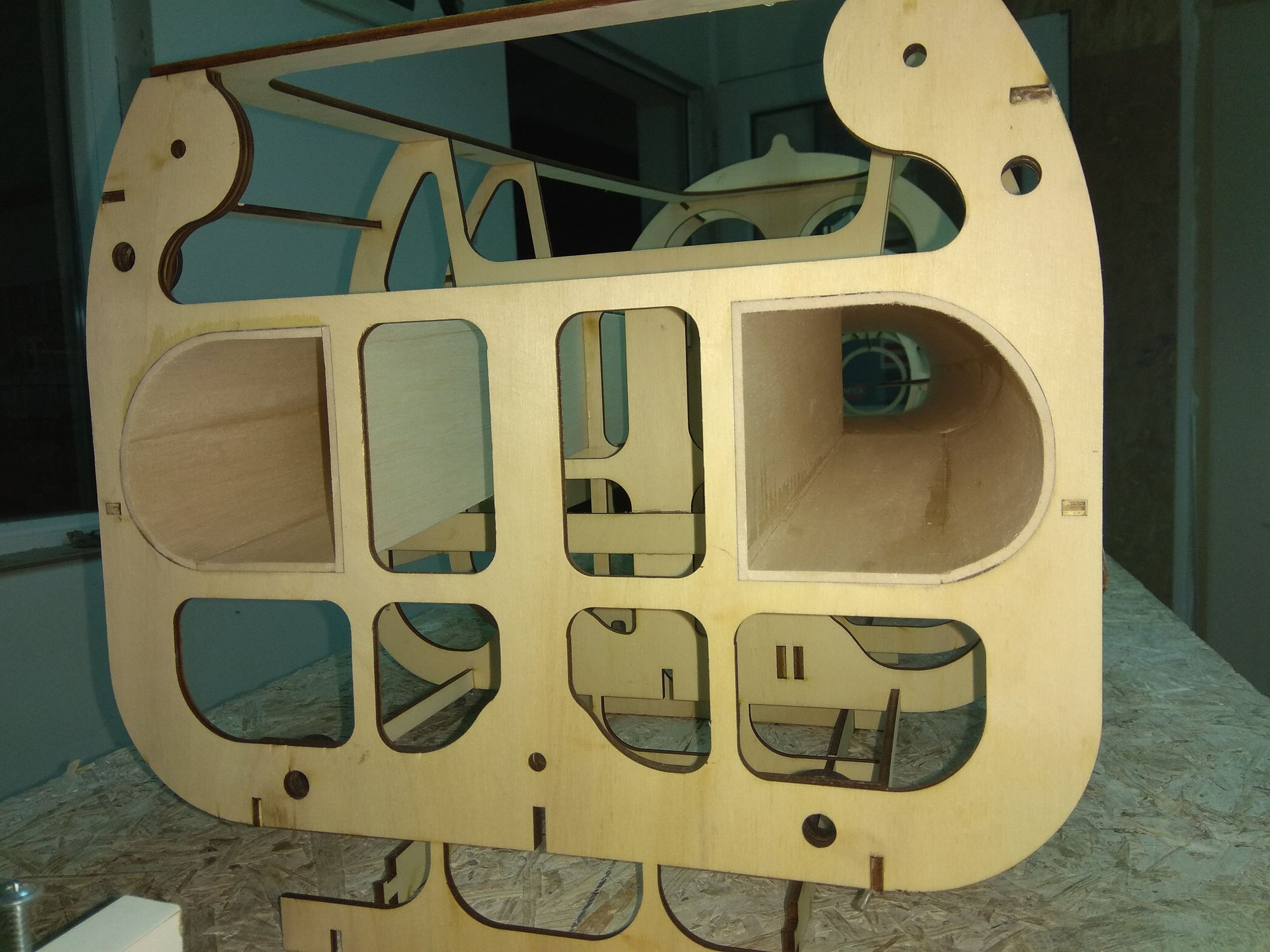
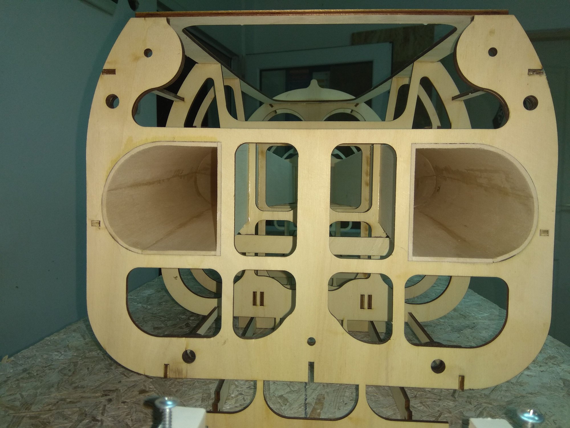

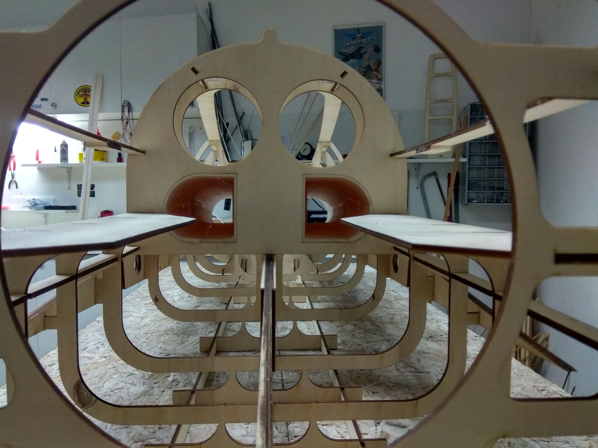

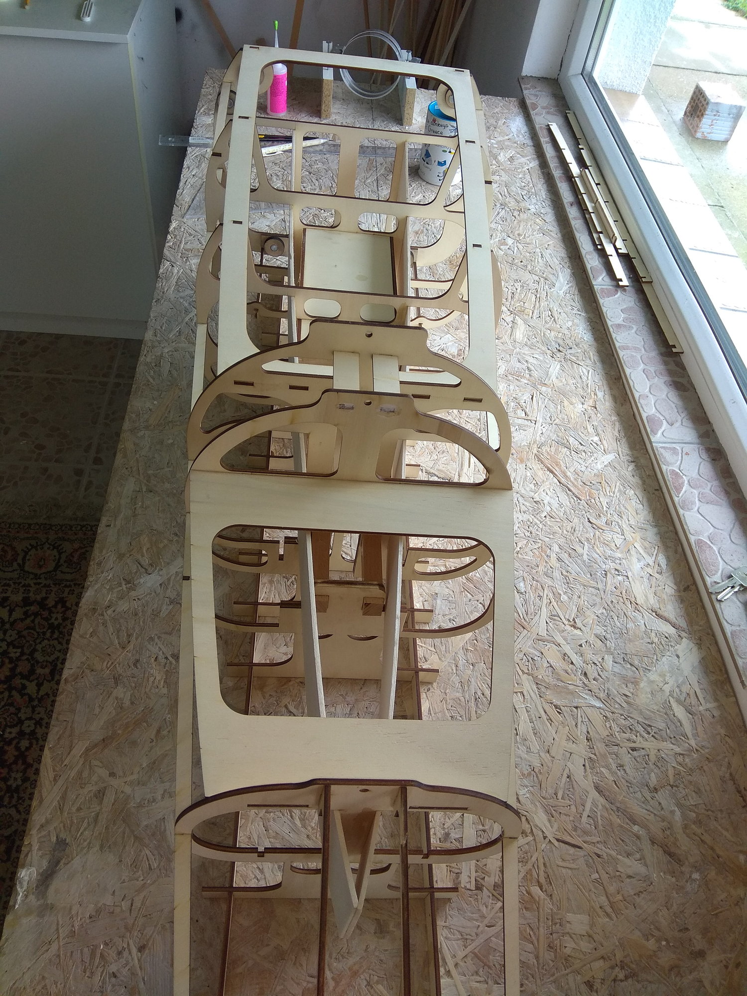
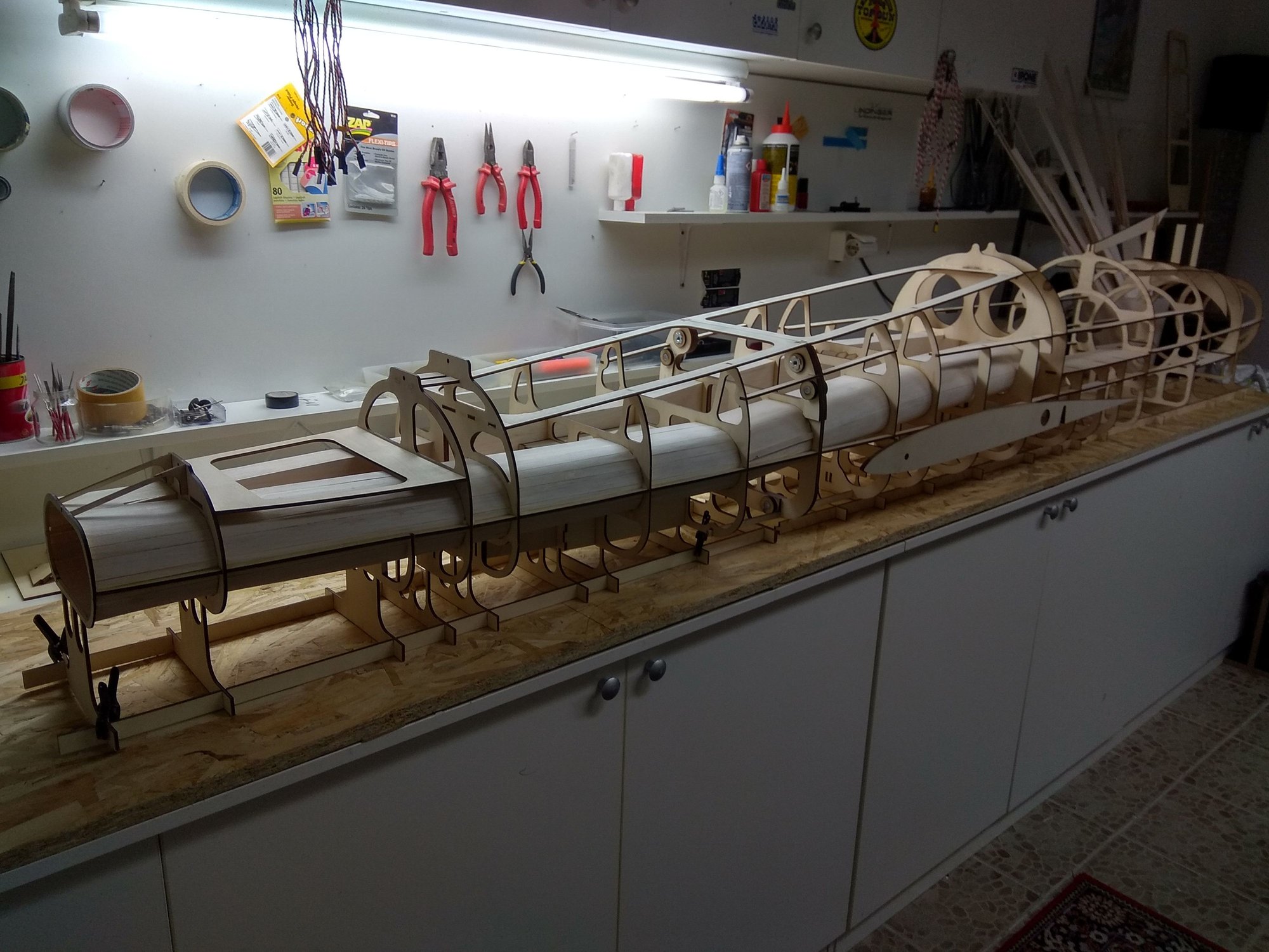
When you assemble the fuselage you can see how long the suction channel is.

Mirce
In the front fuselage part, the channels have a mild curve, so they have to be made of balsa strips that are placed next to each other.
I used CA glue for this process.
The channel in the rear fuselage section was a bit easier to make, because the shape is correct, only in one place it has a slight changeover.
To make balsa easier to bend I used hot water and I used a white carpentry adhesive for gluing.
When you assemble the fuselage you can see how long the suction channel is.
Mirce
 06-29-2018, 02:52 PM
#33
Thread Starter
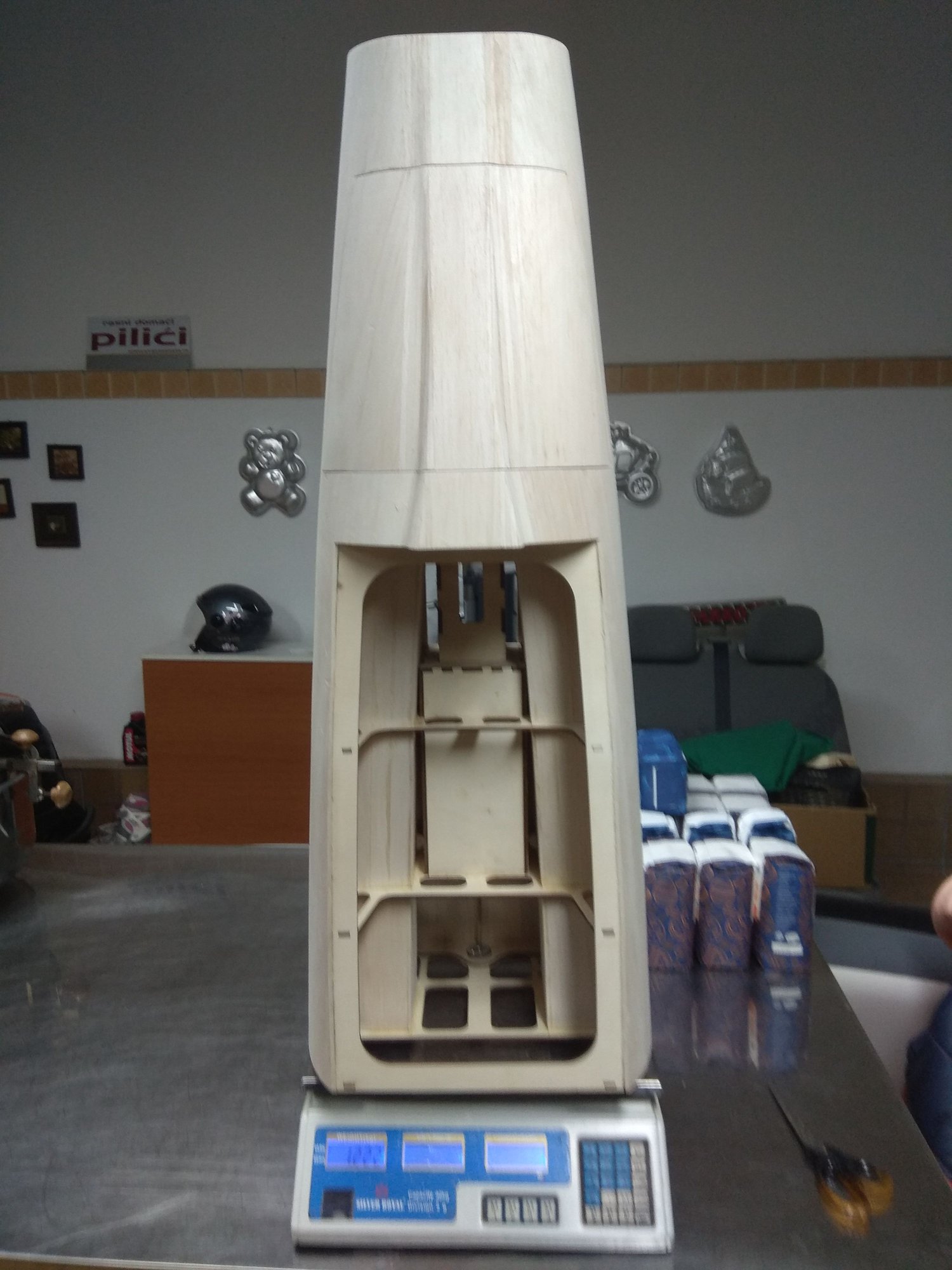
Joe, to be frank I don't know. Weight depend of many aspects, but I hope it will be much, much under 20 kg. We will see...
I'll post weight of parts during building.
I have IQ Hammer 190 SS, but I think it is extremely strong for this model. I can reduced maximum RPM / power. As I told, we will see when come time...
Mirce
I'll post weight of parts during building.
I have IQ Hammer 190 SS, but I think it is extremely strong for this model. I can reduced maximum RPM / power. As I told, we will see when come time...
Mirce
07-03-2018, 04:10 PM
#34
Thread Starter
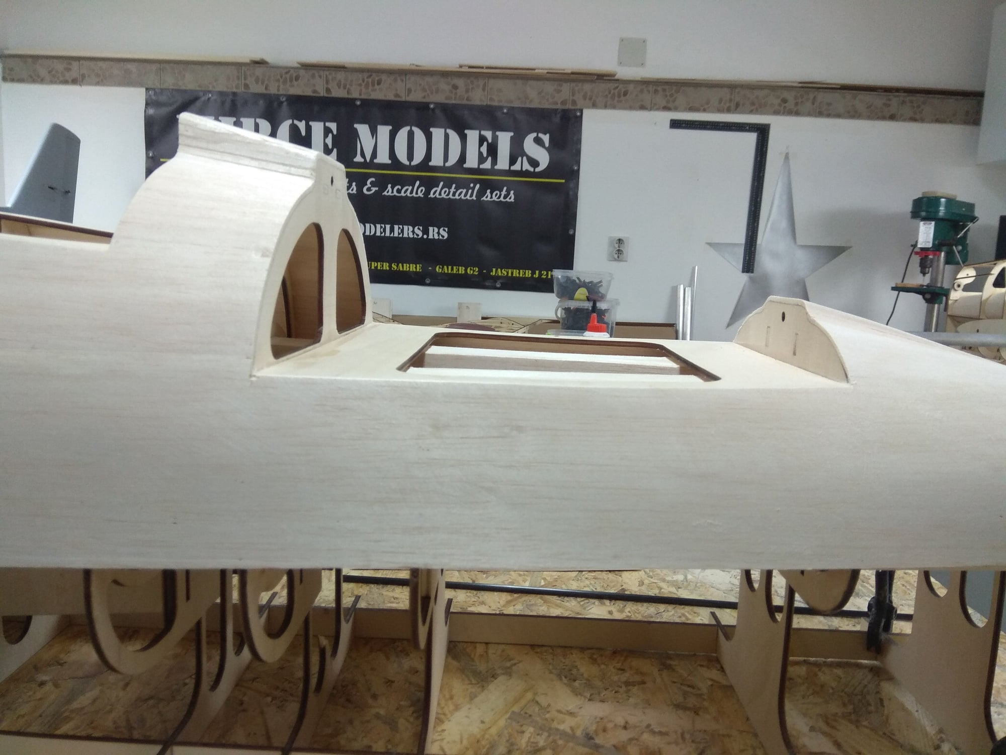
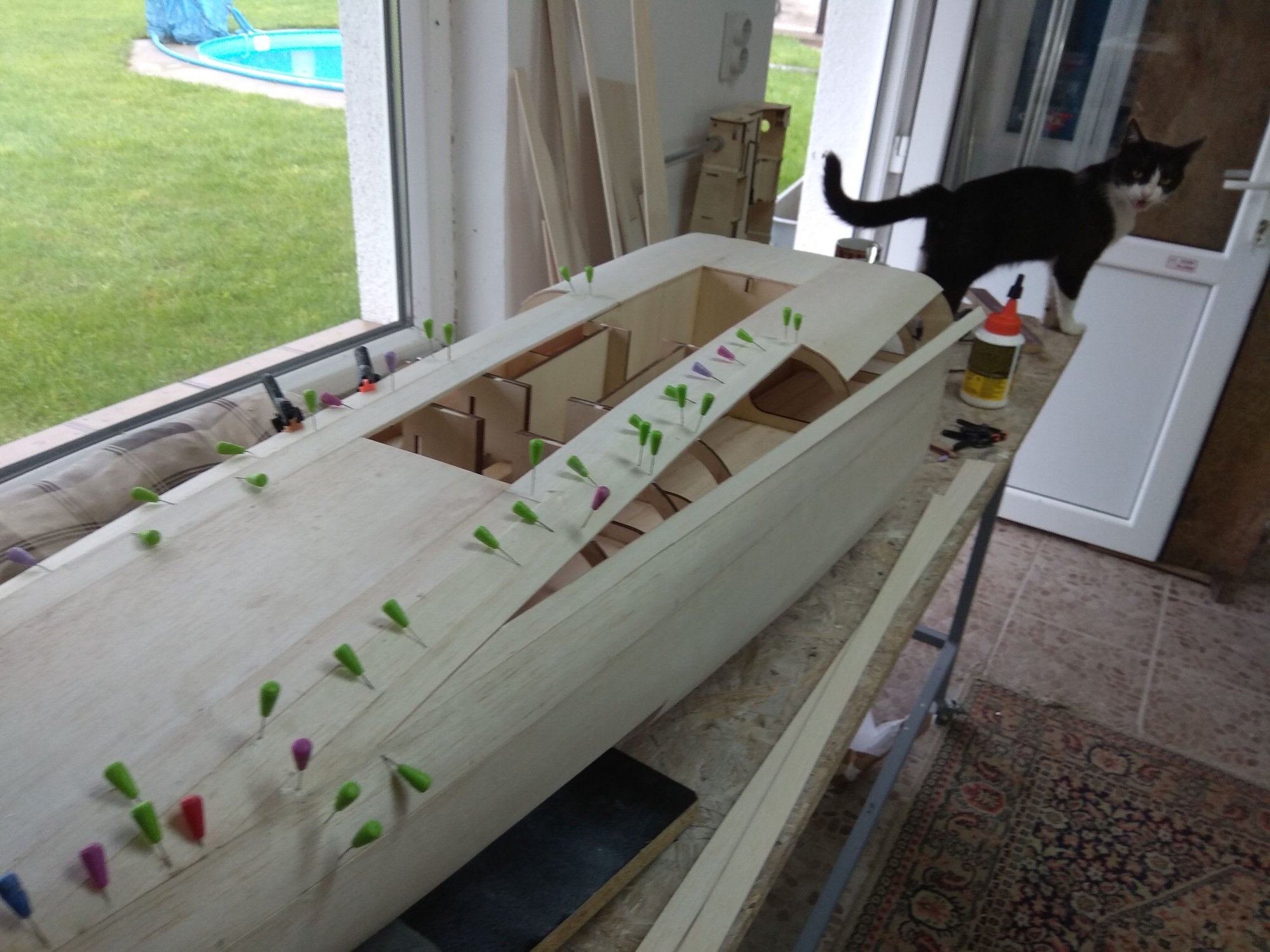
Front fuselage part planking. For this process I use 3 mm balsa & white (carpenter) glue...
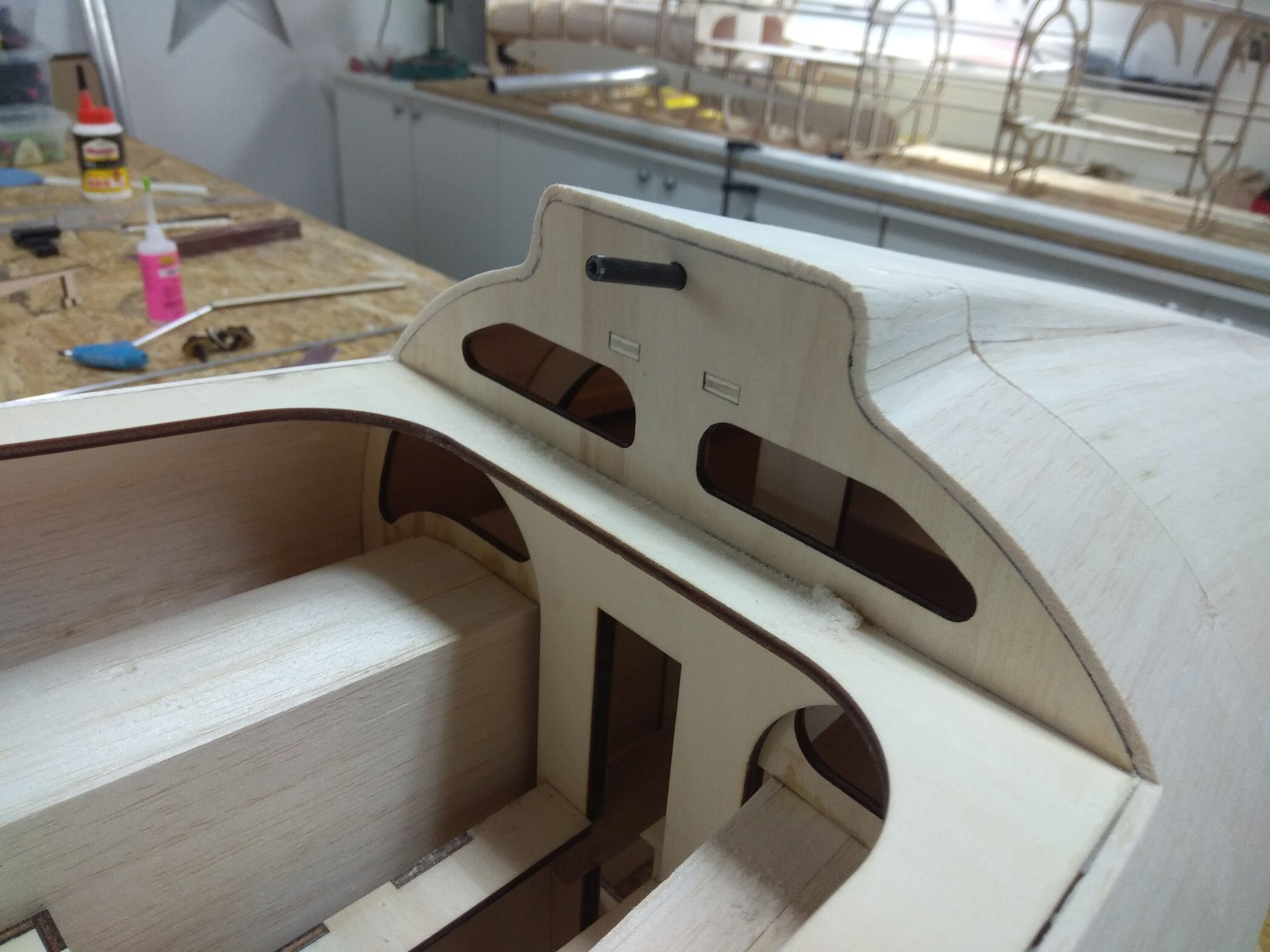
But before that another Damianos great idea, locking system for the front cover and the front side of the canopy.


Now, planking of the front fuselage part...
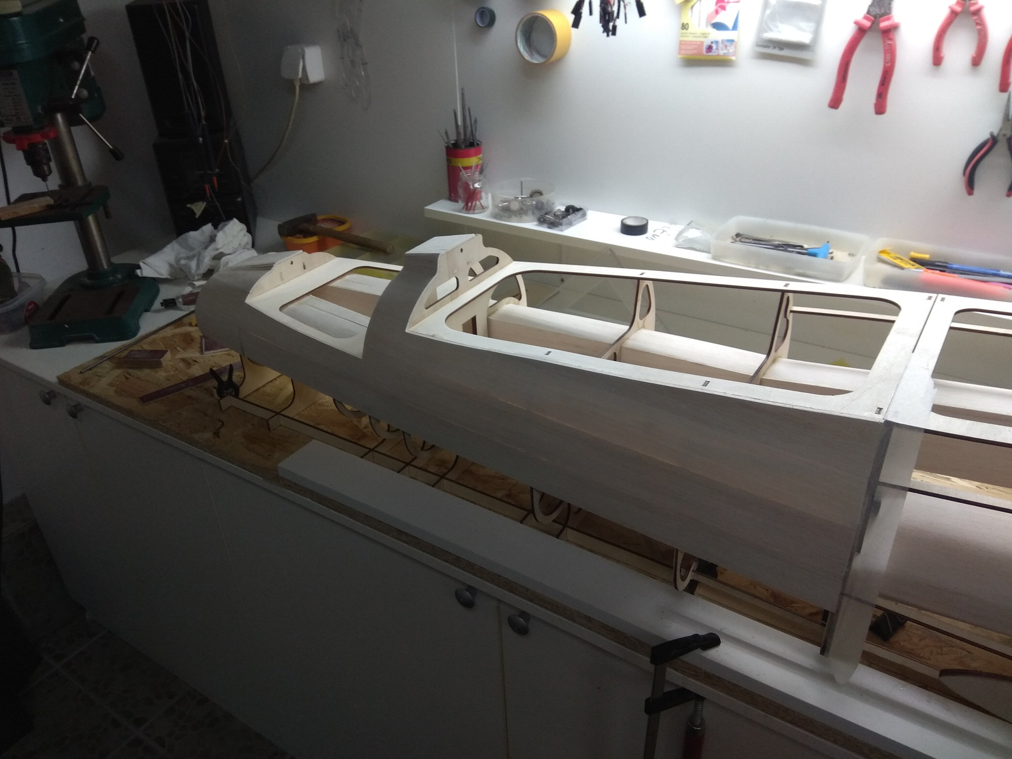

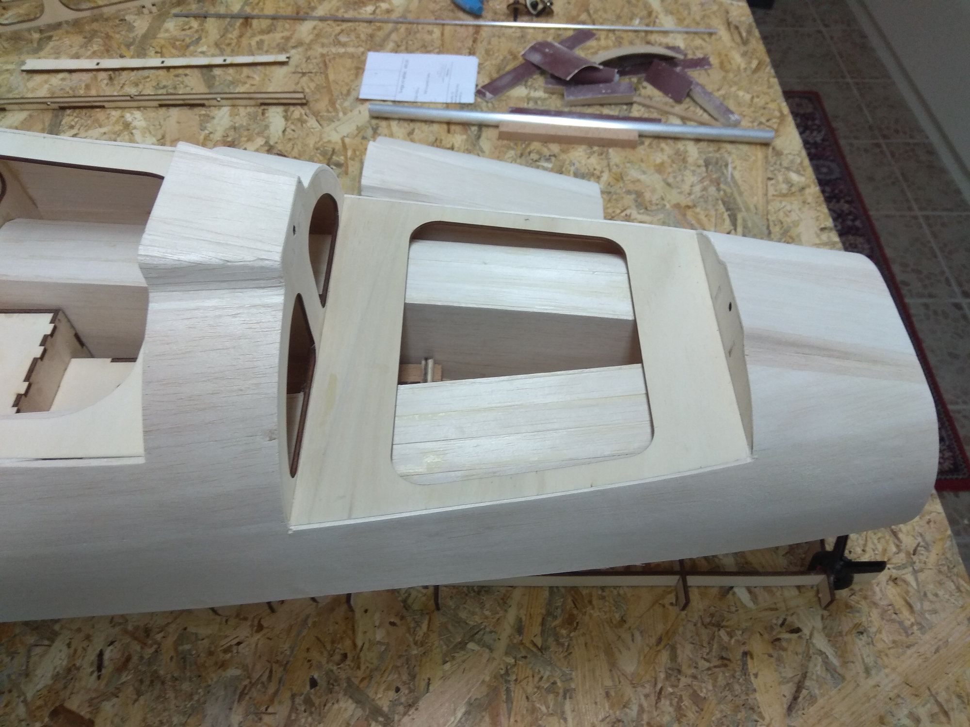
Than, bottom side...
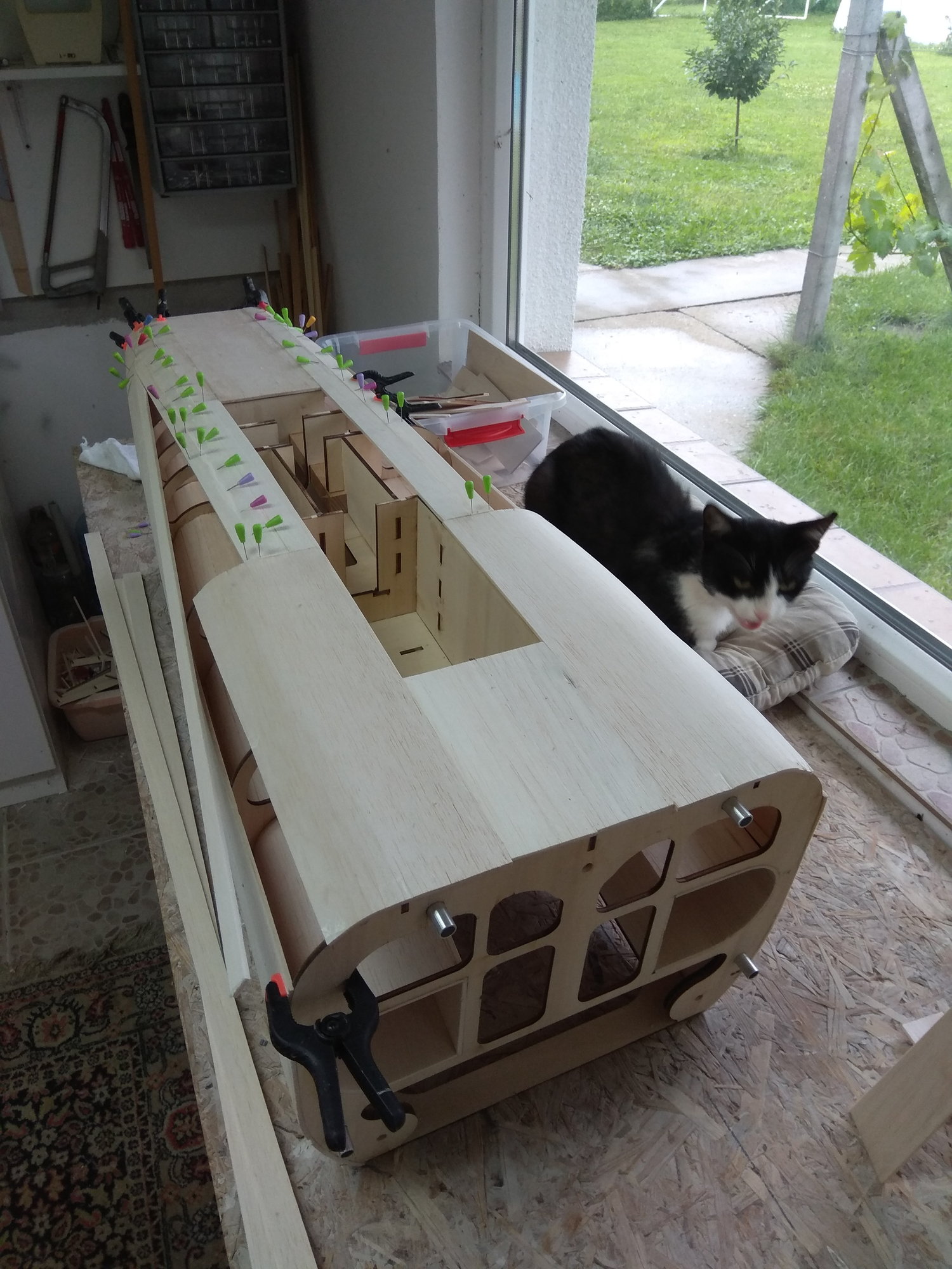
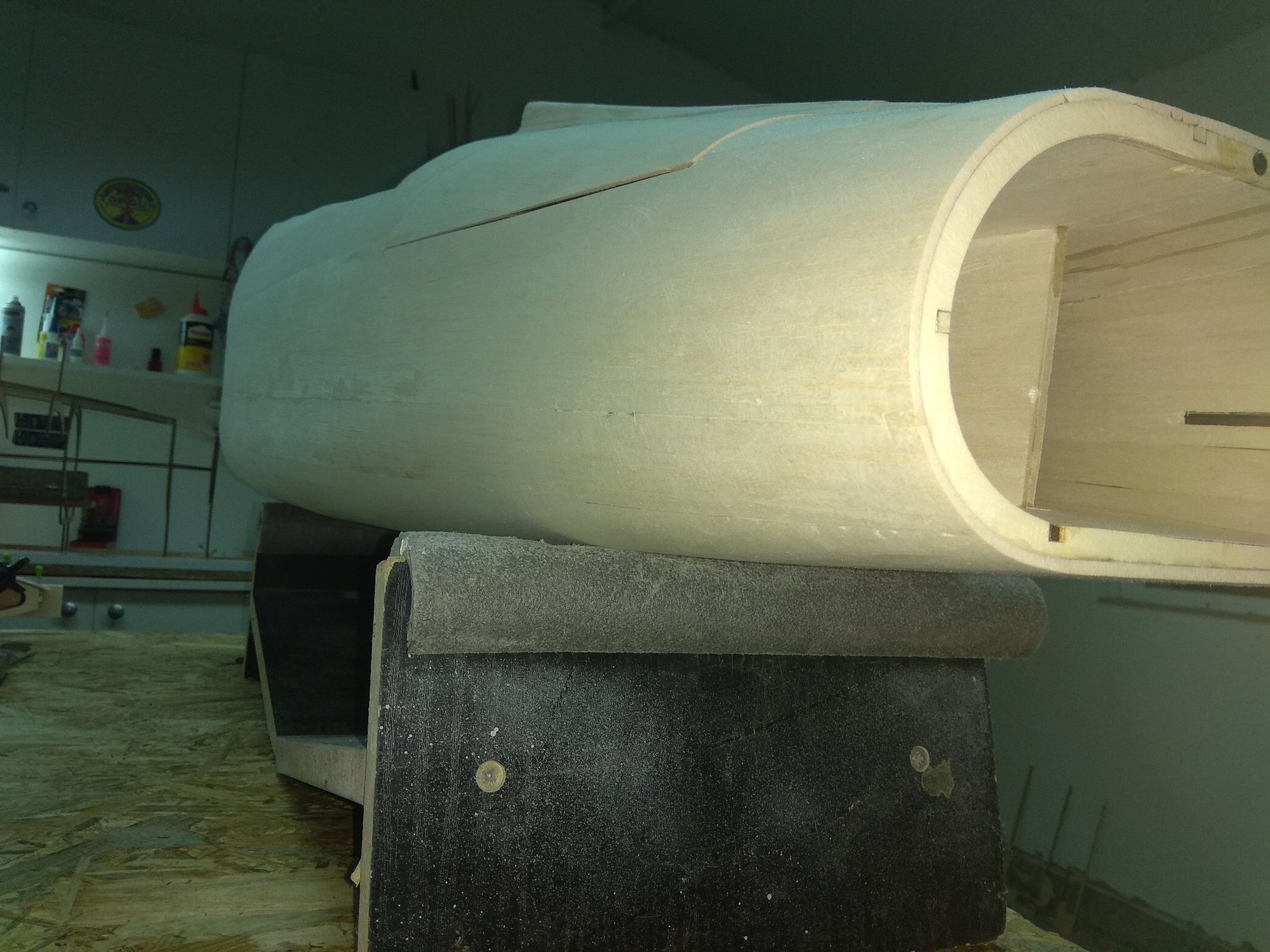
Weight - 1222 gr...
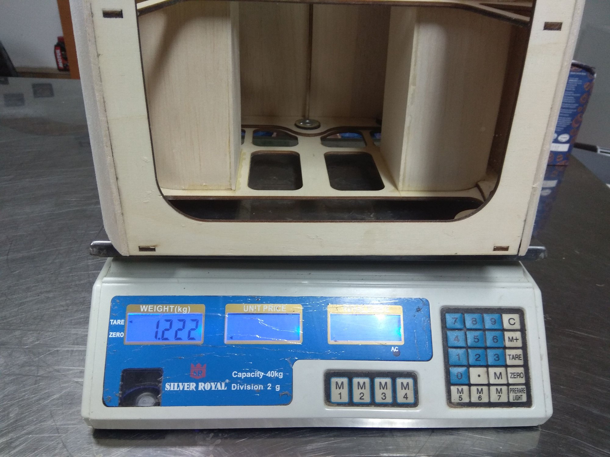
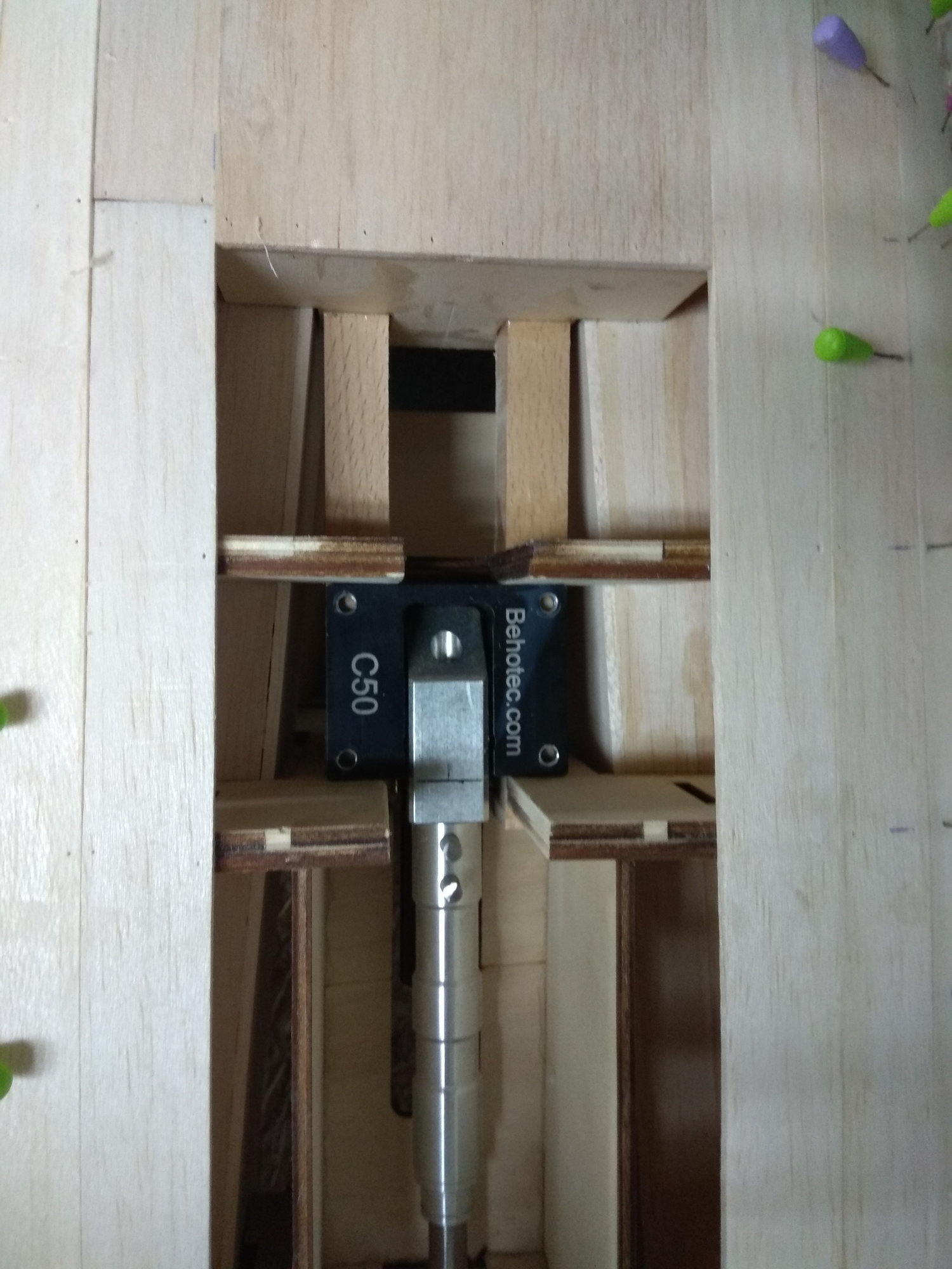
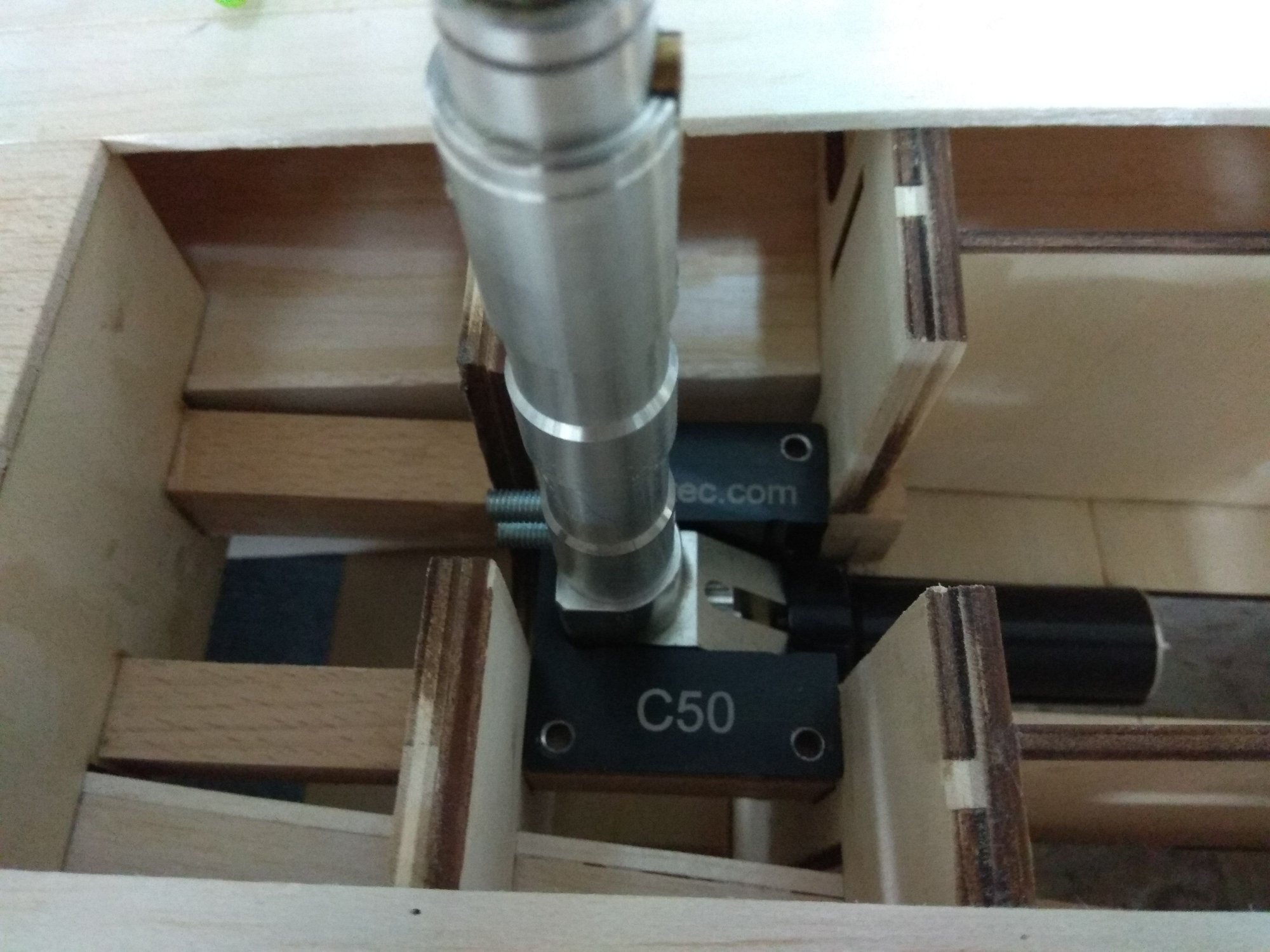
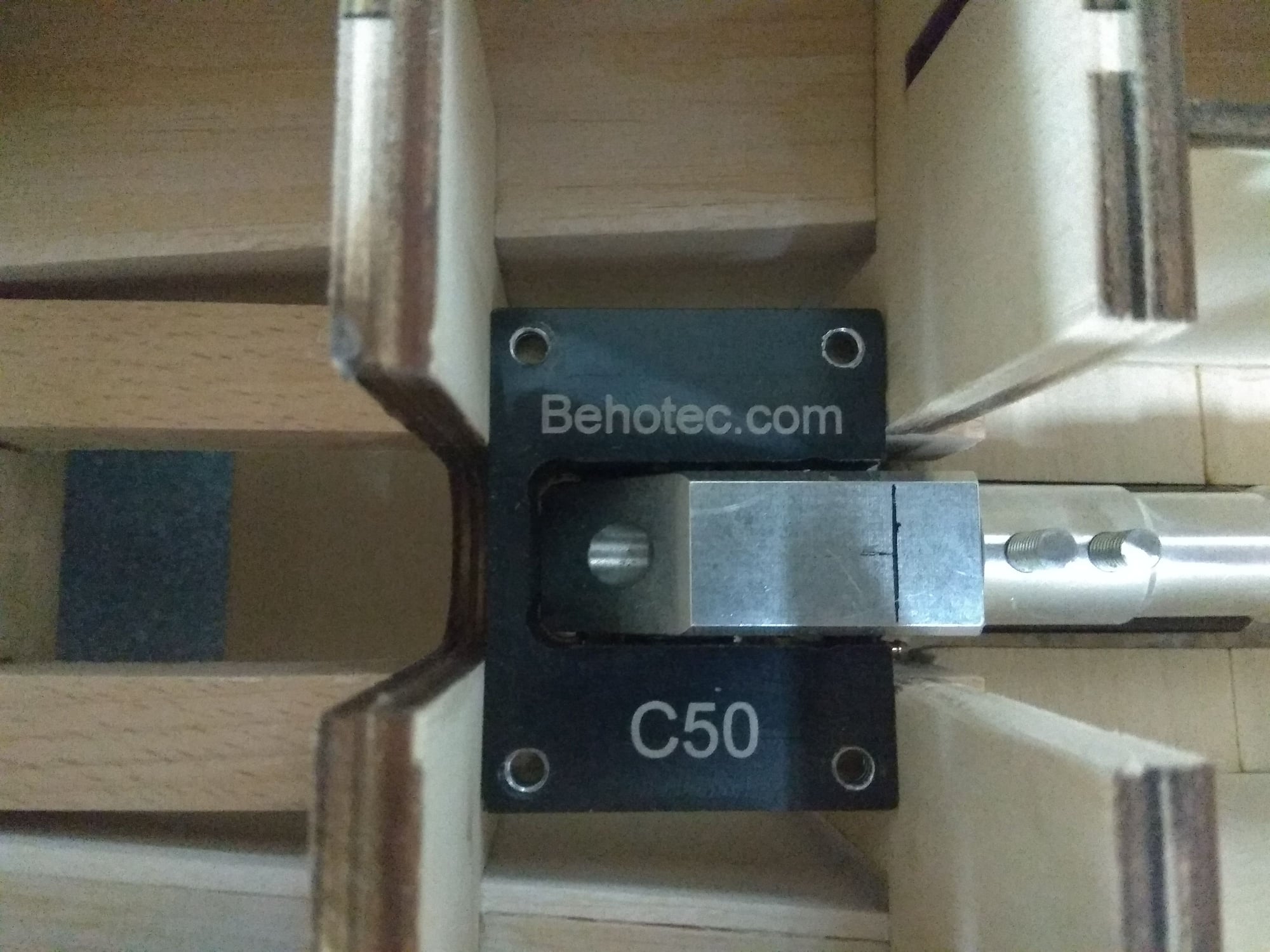
Behotec C 50 landing gear fit prefect in front fuselage part.
OK, strut (leg) is not for F 100, for test I take out this gear from my Jastreb J 21.
Next time wings...
Regards
Mirce
But before that another Damianos great idea, locking system for the front cover and the front side of the canopy.
Now, planking of the front fuselage part...
Than, bottom side...
Weight - 1222 gr...
Behotec C 50 landing gear fit prefect in front fuselage part.
OK, strut (leg) is not for F 100, for test I take out this gear from my Jastreb J 21.
Next time wings...
Regards
Mirce
 07-05-2018, 10:29 PM
#37
Thread Starter
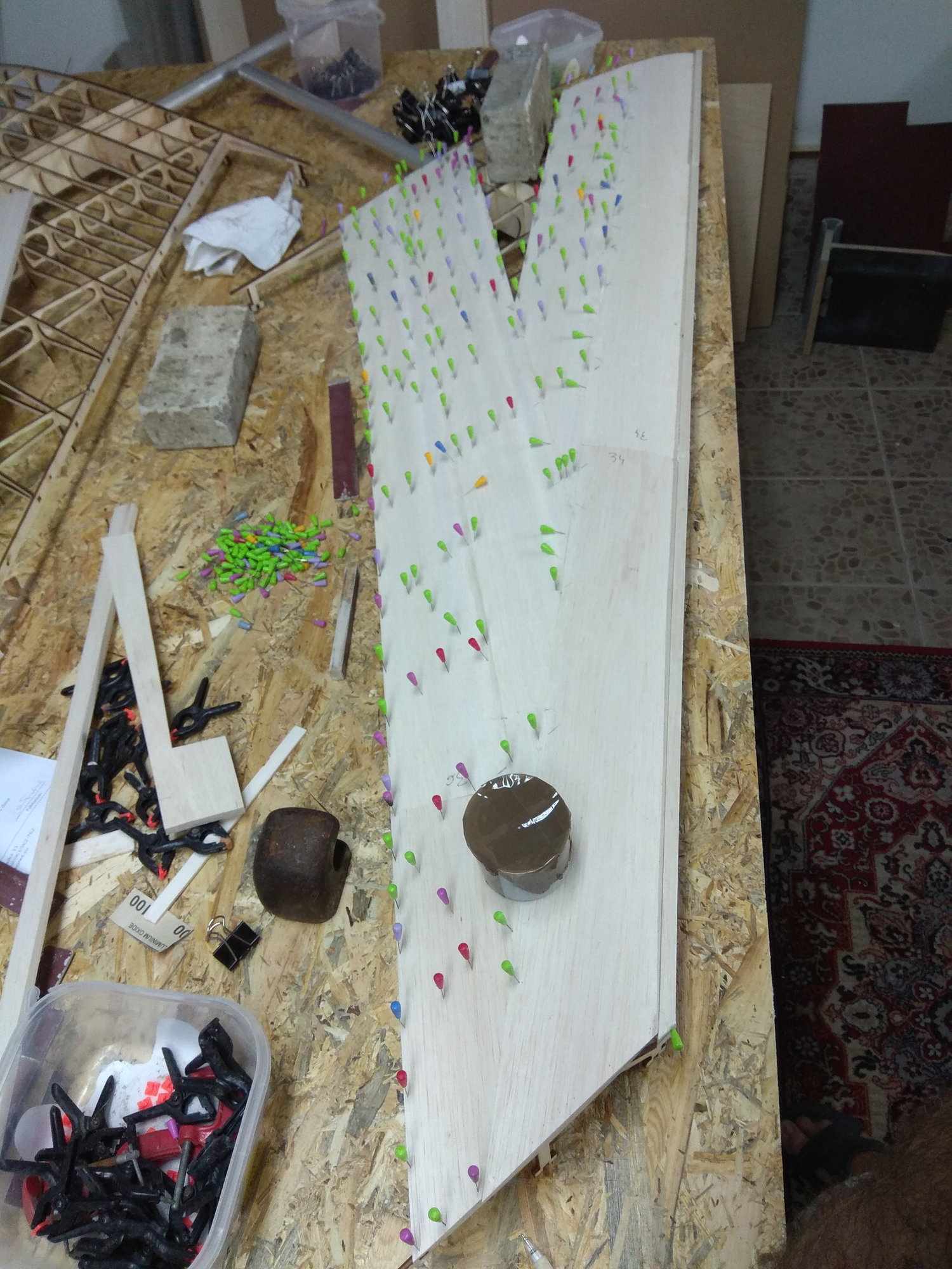
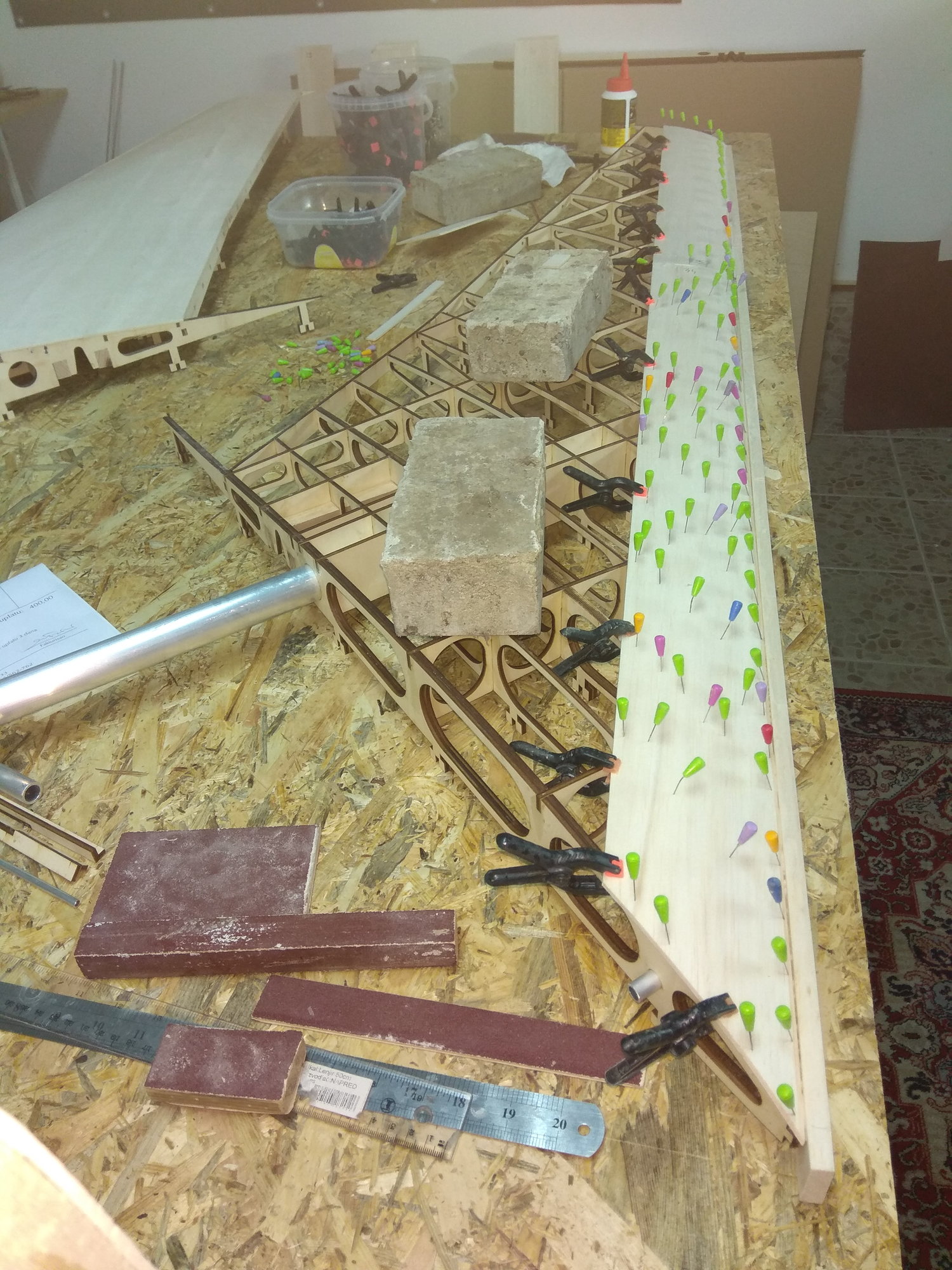
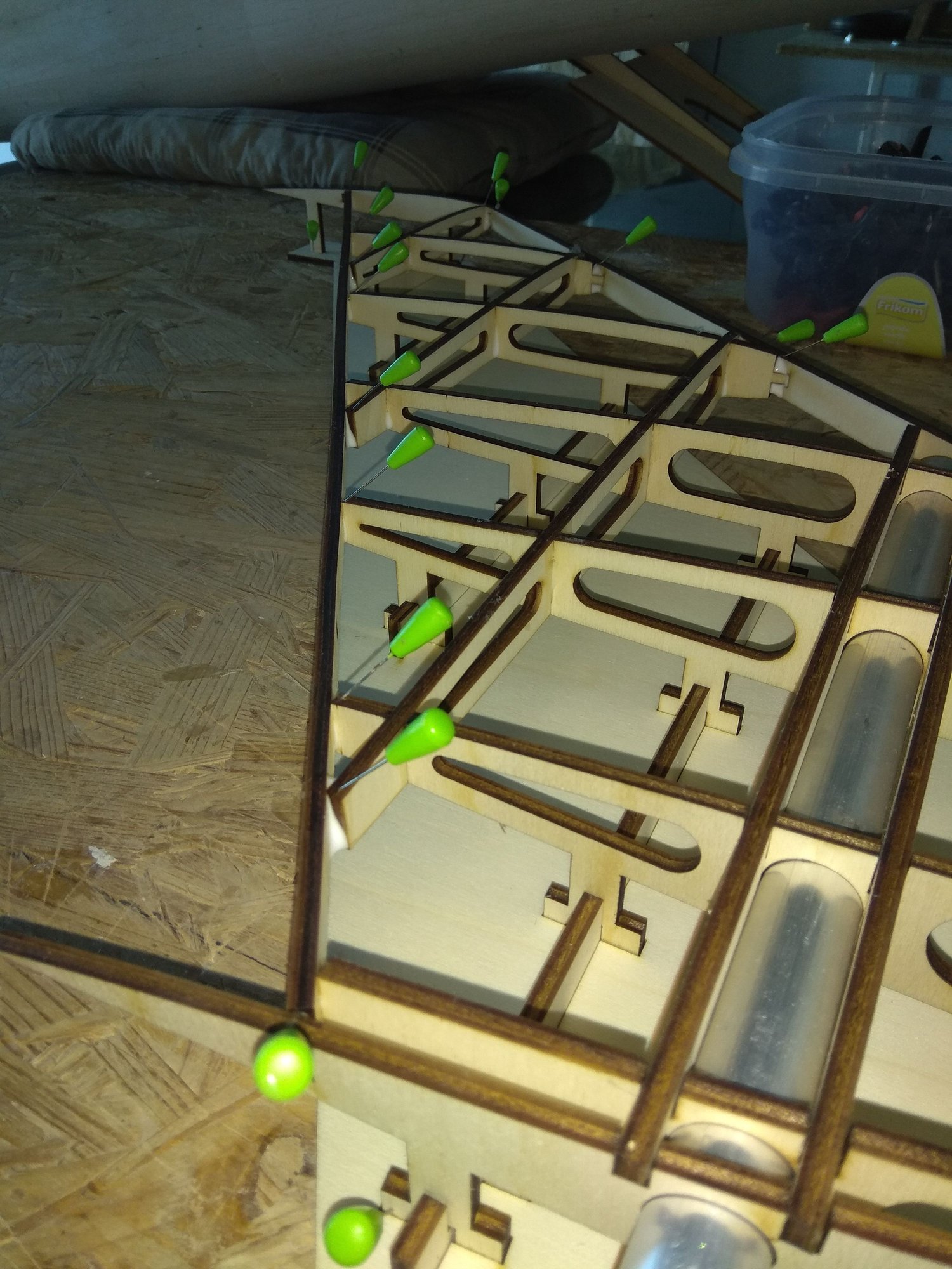
Thank you Sparhawk and Kevin. Today, wings sheeting...
First thing was to glue 10 mm balsa for leading edge. It's little higher, because the first 3 mm balsa plate is glued to it.
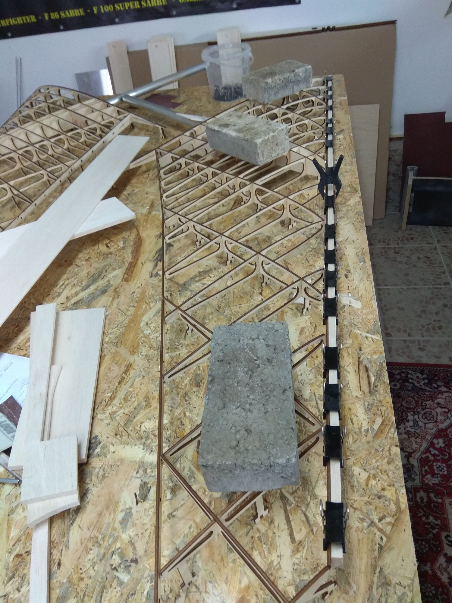
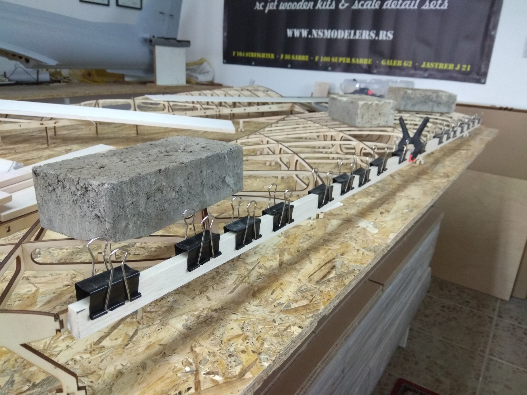
Now first balsa plates, near leading edge.
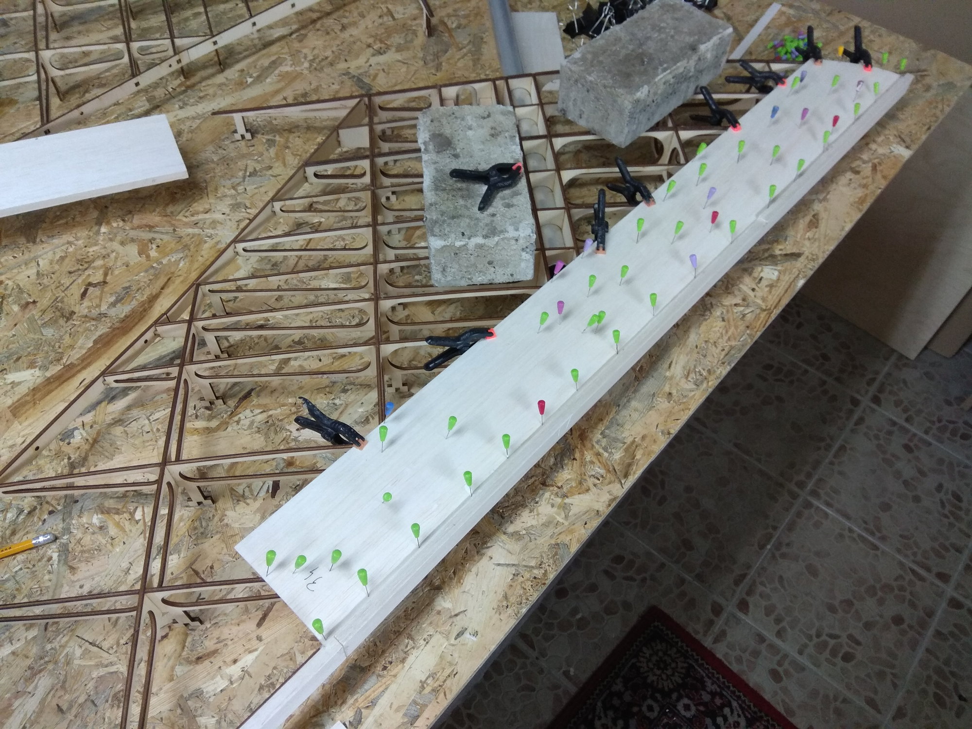
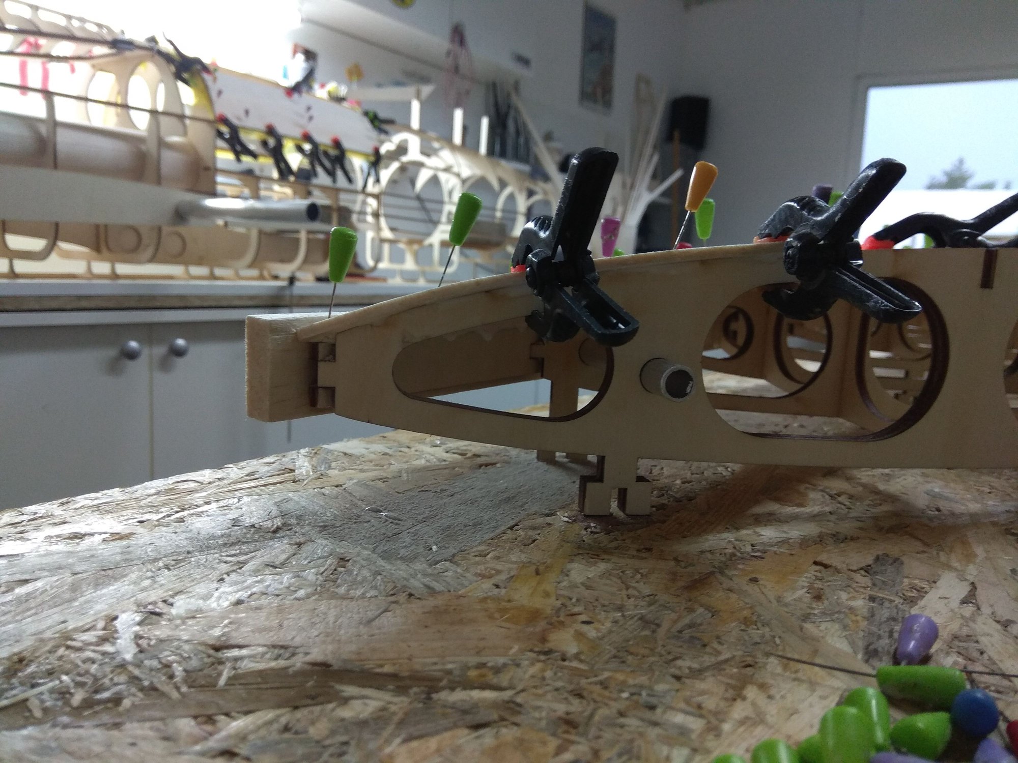
Next was on trailing edge and after that one in front and one behind...
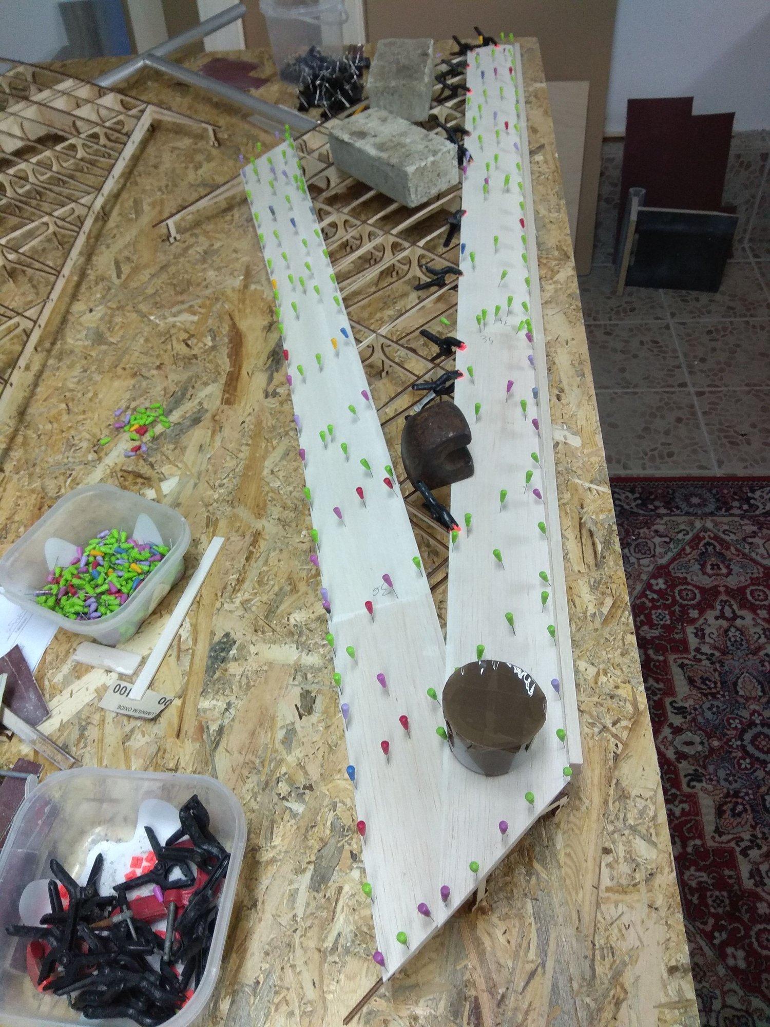
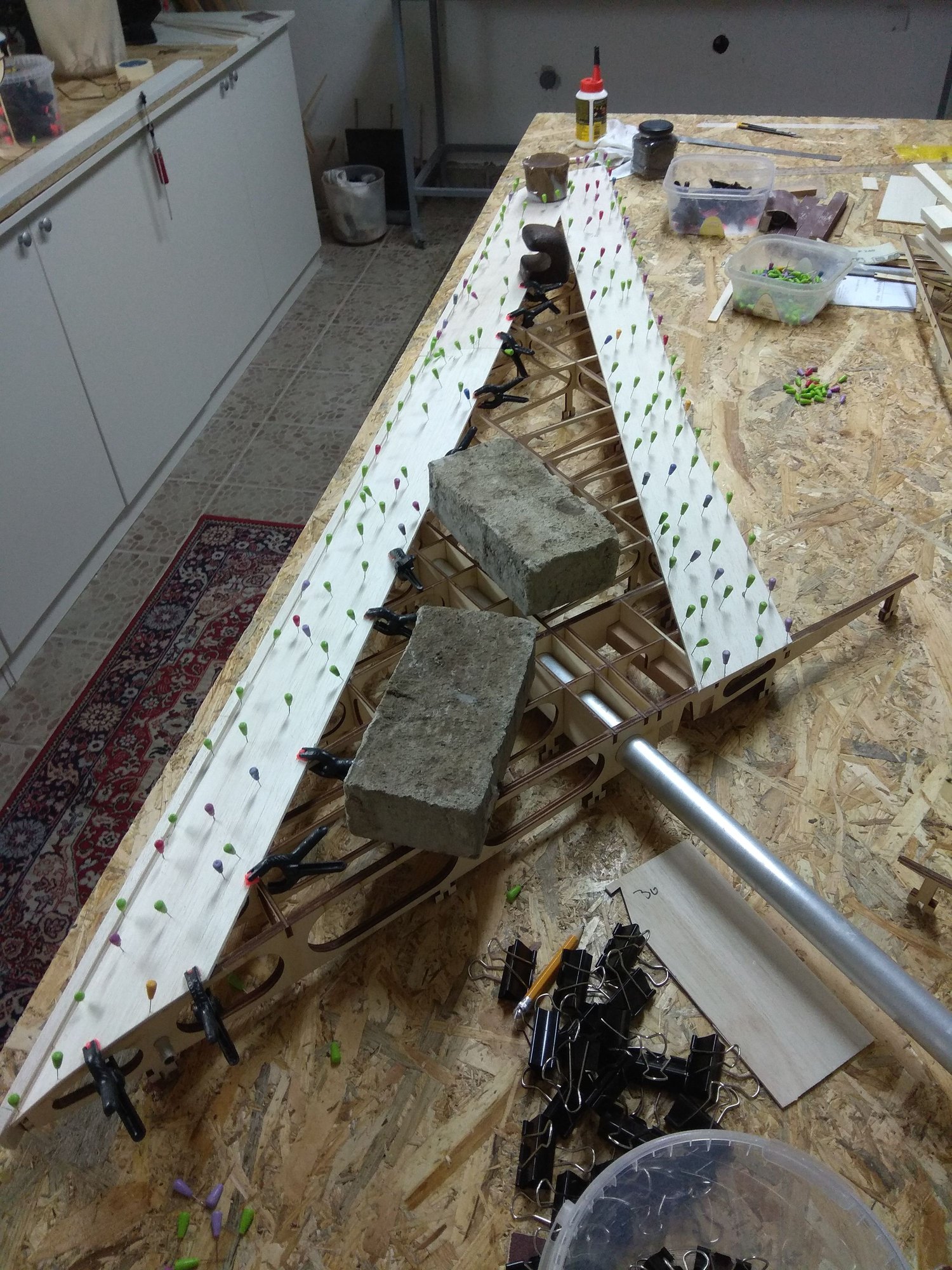
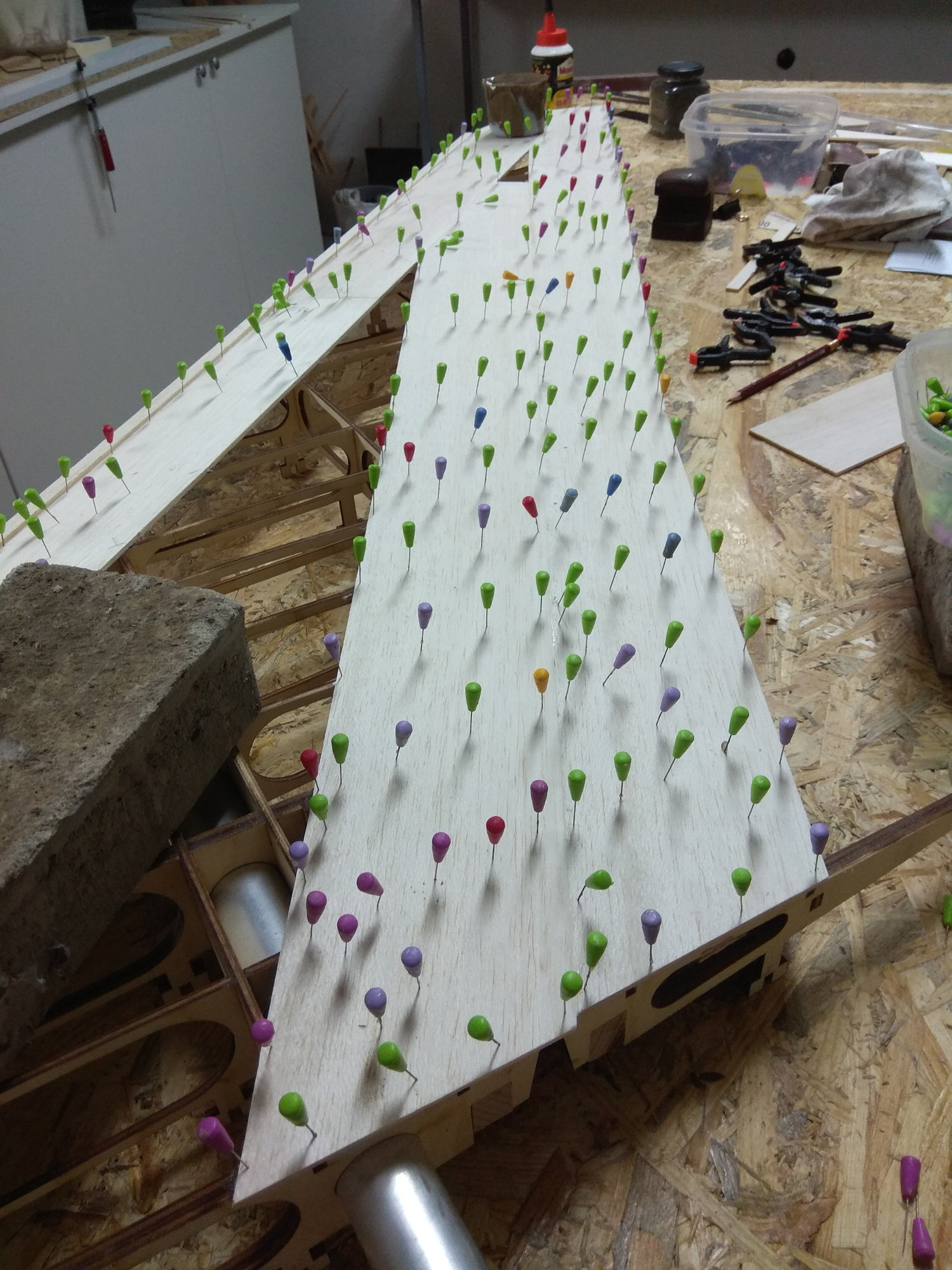
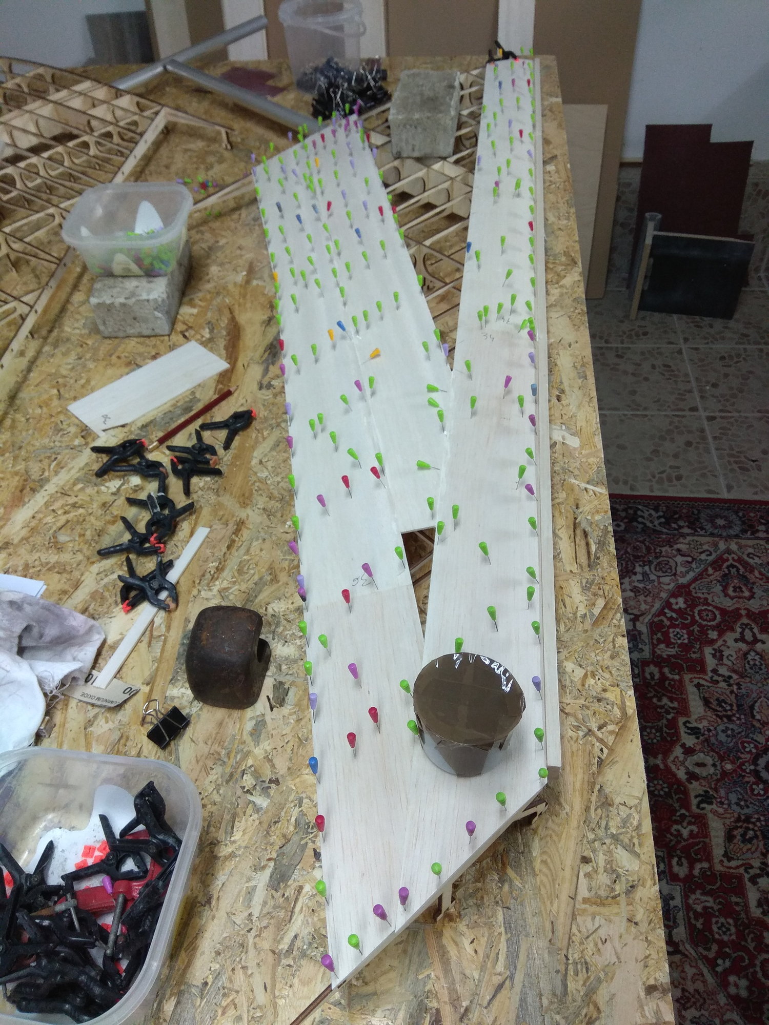
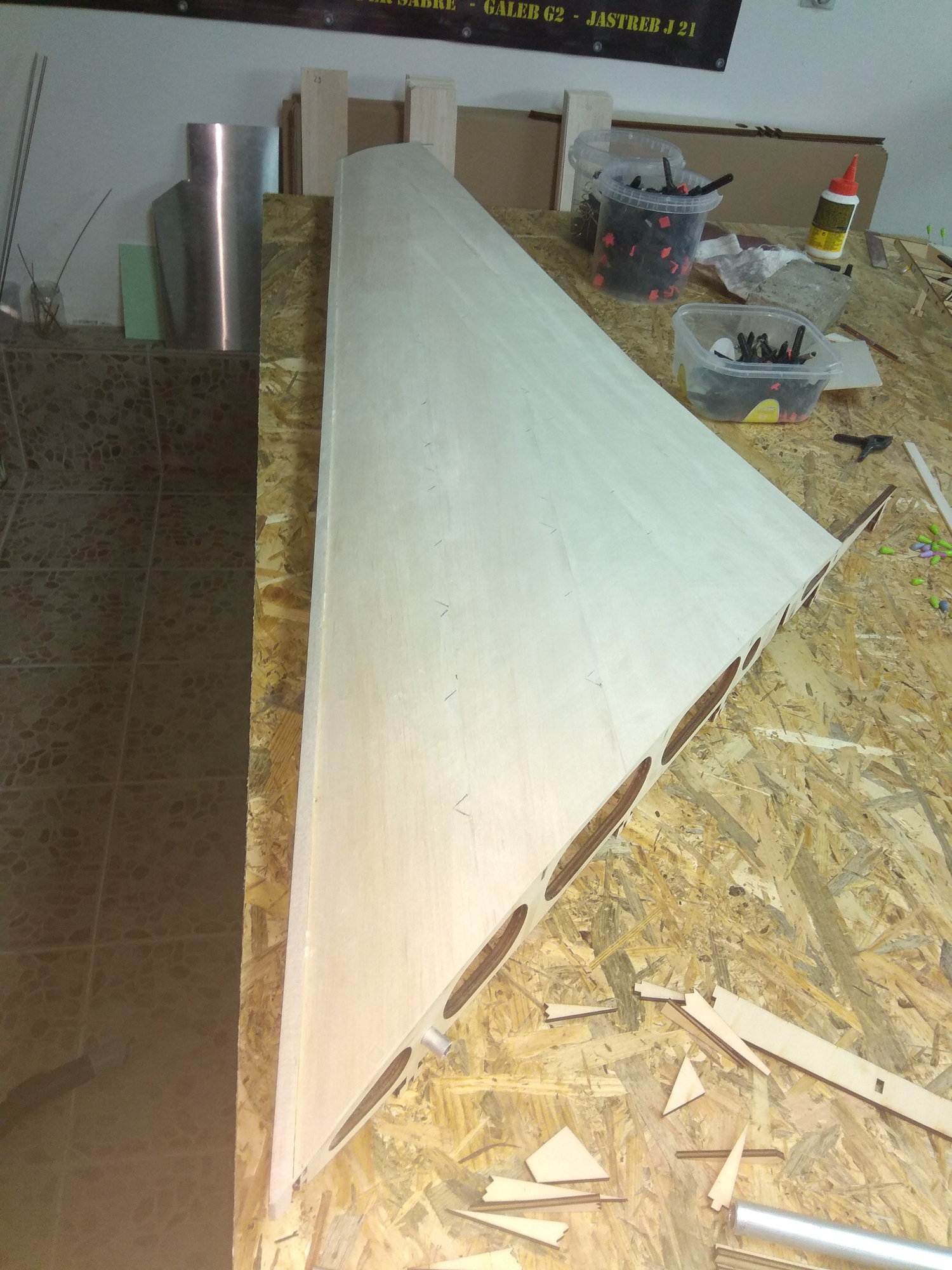
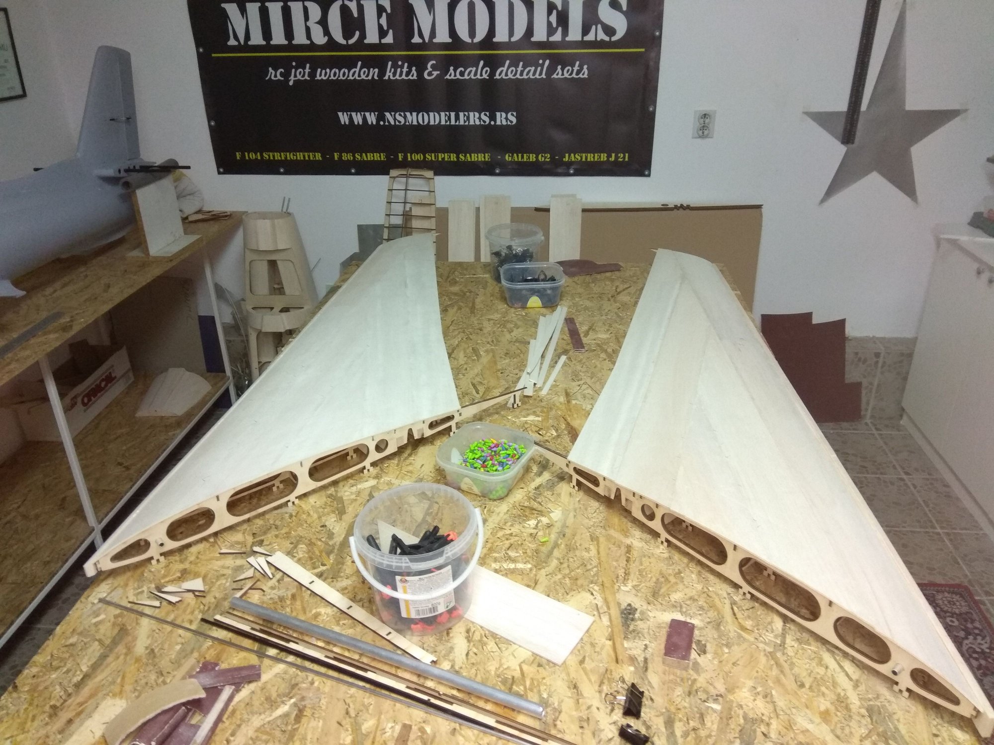
Than copy - paste everything on other wing...
I try how fit landing gears. I haven't struts right now, this struts are from Jastreb J 21, my other jet model.
Struts length and wheel dimensions I'll post here later...

Regards
Mirce
First thing was to glue 10 mm balsa for leading edge. It's little higher, because the first 3 mm balsa plate is glued to it.
Now first balsa plates, near leading edge.
Next was on trailing edge and after that one in front and one behind...
Than copy - paste everything on other wing...
I try how fit landing gears. I haven't struts right now, this struts are from Jastreb J 21, my other jet model.
Struts length and wheel dimensions I'll post here later...
Regards
Mirce
Last edited by mirce; 07-06-2018 at 05:24 AM.
07-06-2018, 05:42 AM
#40

Beautiful Build, I am about to start an all wood jet build myself (Sea Vixen). Thanks to you, looks like I have another wood jet model to put in the que. Not sure if I saw the power requirement for this airframe and estimated cost. Again, beautiful build. Chic
07-06-2018, 06:46 AM
#42
Thread Starter
Redtail, more information & price about F 100 wooden kit and parts you can find on my web site. Link is below...
Kevin, that is Behotec landing gears & struts. Right dimension for F 100 I'll post here later.
Thanks for nice comments...
Regards
Mirce
Kevin, that is Behotec landing gears & struts. Right dimension for F 100 I'll post here later.
Thanks for nice comments...
Regards
Mirce
07-06-2018, 07:31 AM
#45
Join Date: Jan 2007
Location: farnborough, , UNITED KINGDOM
Posts: 3,294
Likes: 0
Received 1 Like
on
1 Post
Lovely kit Mirce, fantastic work.
Regards landing gear why don't gear manufacturers make versions of the gear with larger footprint bases, the loads imposed by these narrow plates on the mounts is crazy, wider bases and spread the load across the structure...................... not rocket science.
marcs
Regards landing gear why don't gear manufacturers make versions of the gear with larger footprint bases, the loads imposed by these narrow plates on the mounts is crazy, wider bases and spread the load across the structure...................... not rocket science.
marcs
07-06-2018, 01:53 PM
#46
Thread Starter
Kevin, right now there are no hard points for wing tanks, but before sheeting they will be install. I wait on Martin to finish complete wing tank, pylon & wing structure drawings and than to show it and prepare parts on laser cut.
Mark, thanks on kind words for model, but question about gears is for Behotec or some other gear manufacturers.
New photos soon...
Mirce
Mark, thanks on kind words for model, but question about gears is for Behotec or some other gear manufacturers.
New photos soon...
Mirce
Last edited by mirce; 07-06-2018 at 10:45 PM.
07-06-2018, 11:15 PM
#47
Thread Starter
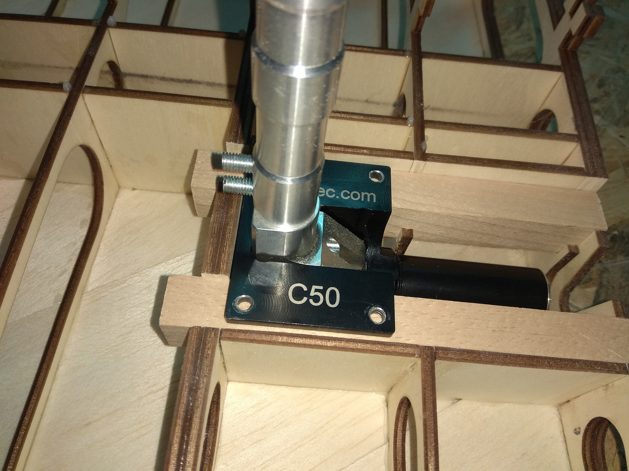
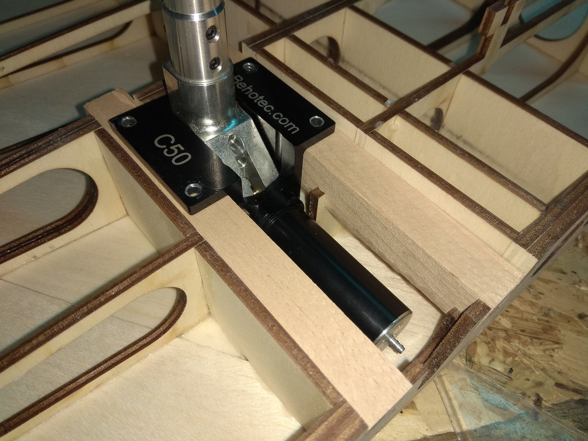
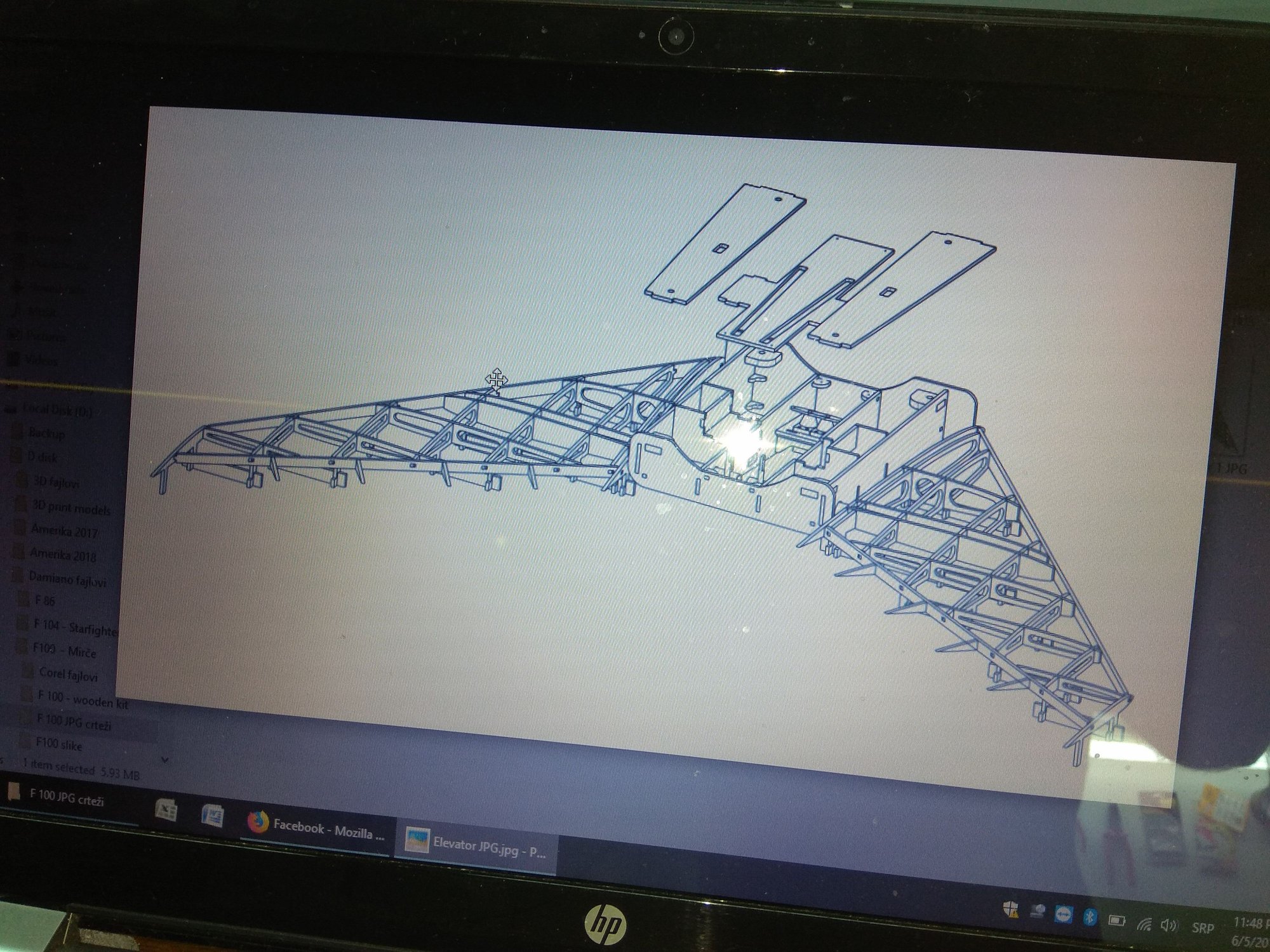
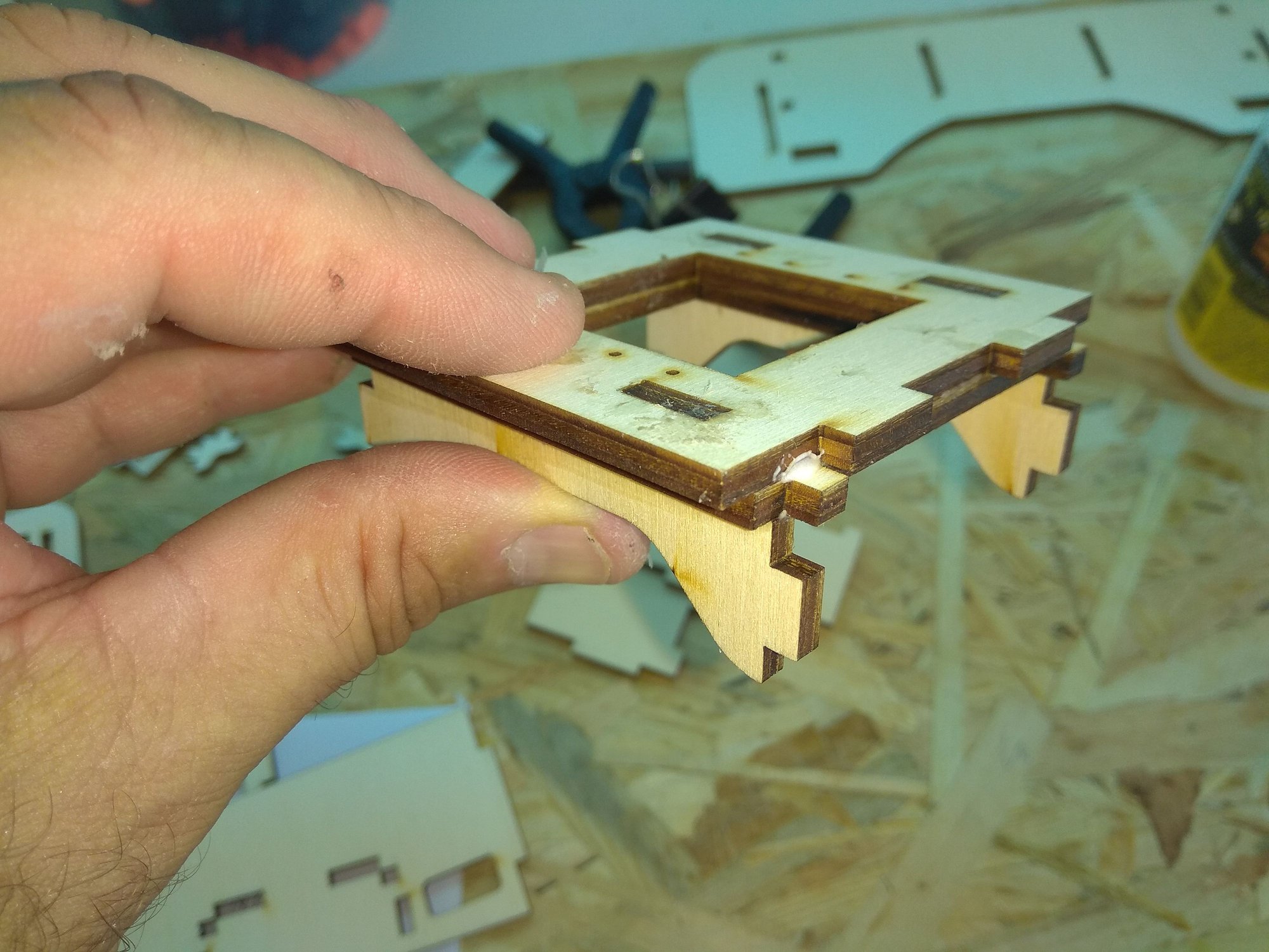
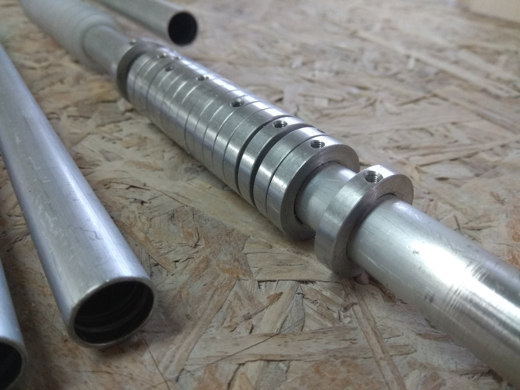
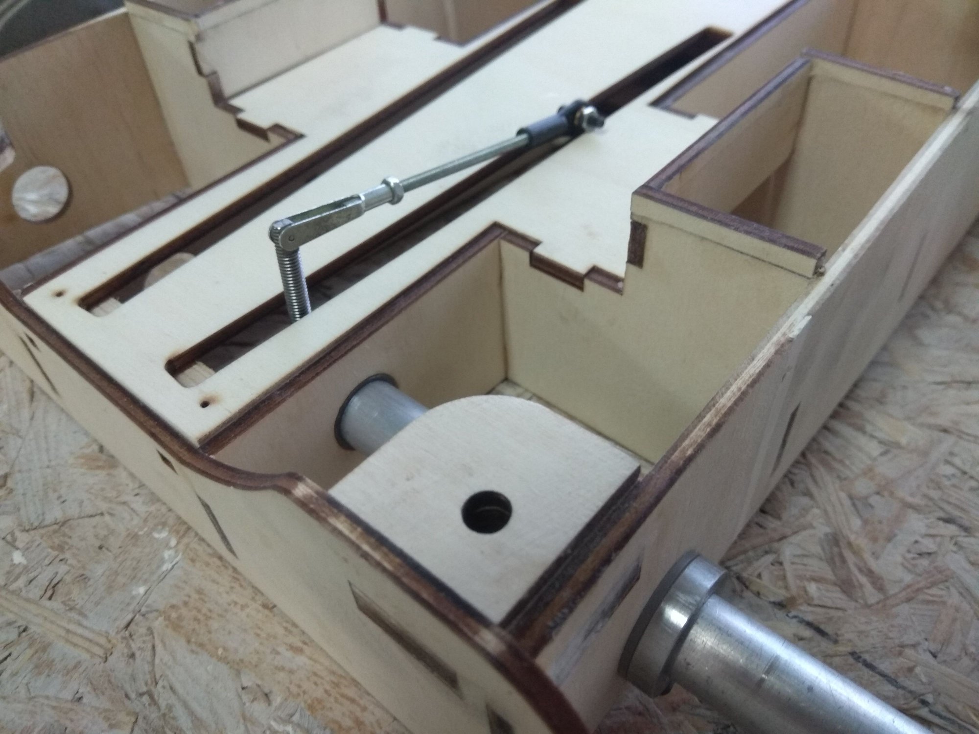
Another great Damiano's design is elevators system.
On bottom fuselage side is "box" where are servos and elevator shafts. With four screws you can remove complete system for easier transport.
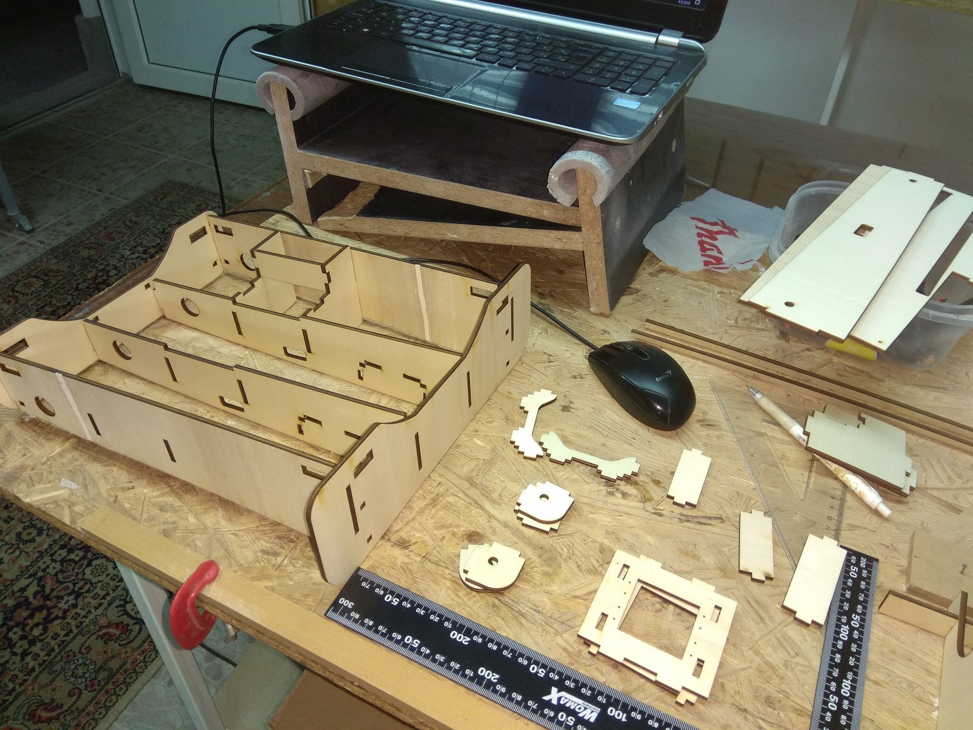
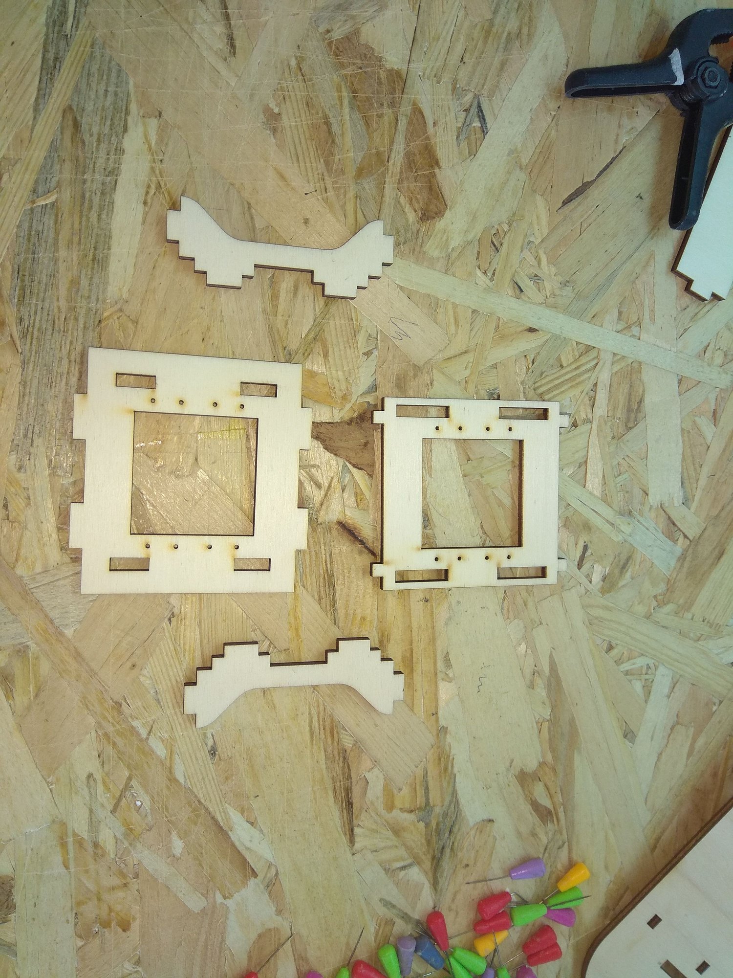


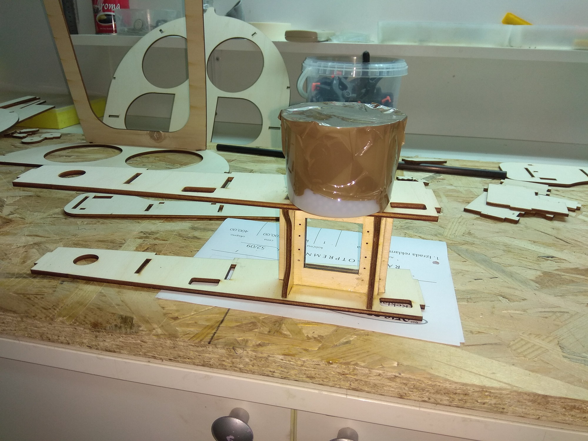
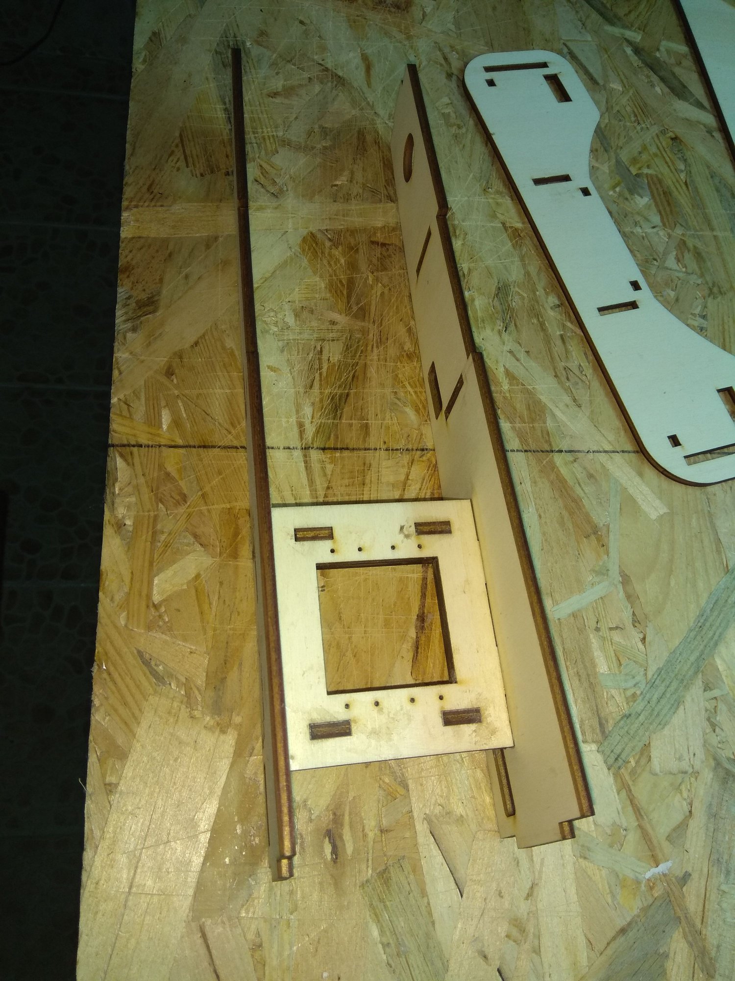


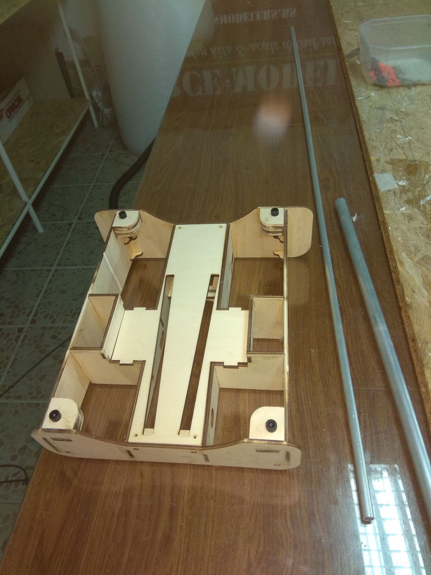
In my friends machine workshop was made all plastic & metal small parts...
On bottom fuselage side is "box" where are servos and elevator shafts. With four screws you can remove complete system for easier transport.
In my friends machine workshop was made all plastic & metal small parts...
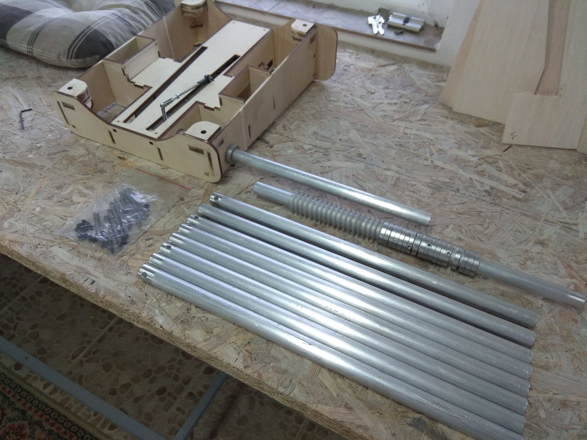
The entire assembly for one F 100 model has:
- two aluminum tubes for elevators
- two plastic plugs
- four plastic rings
- four aluminum fasteners for fixing
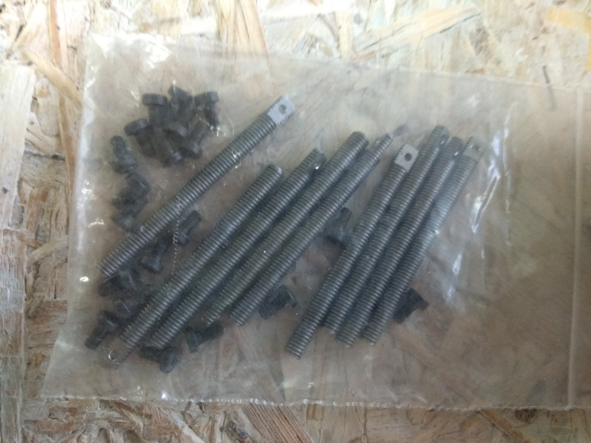
- two stainless steel thread for connection with servo
- two aluminum tubes for elevators
- two plastic plugs
- four plastic rings
- four aluminum fasteners for fixing
- two stainless steel thread for connection with servo
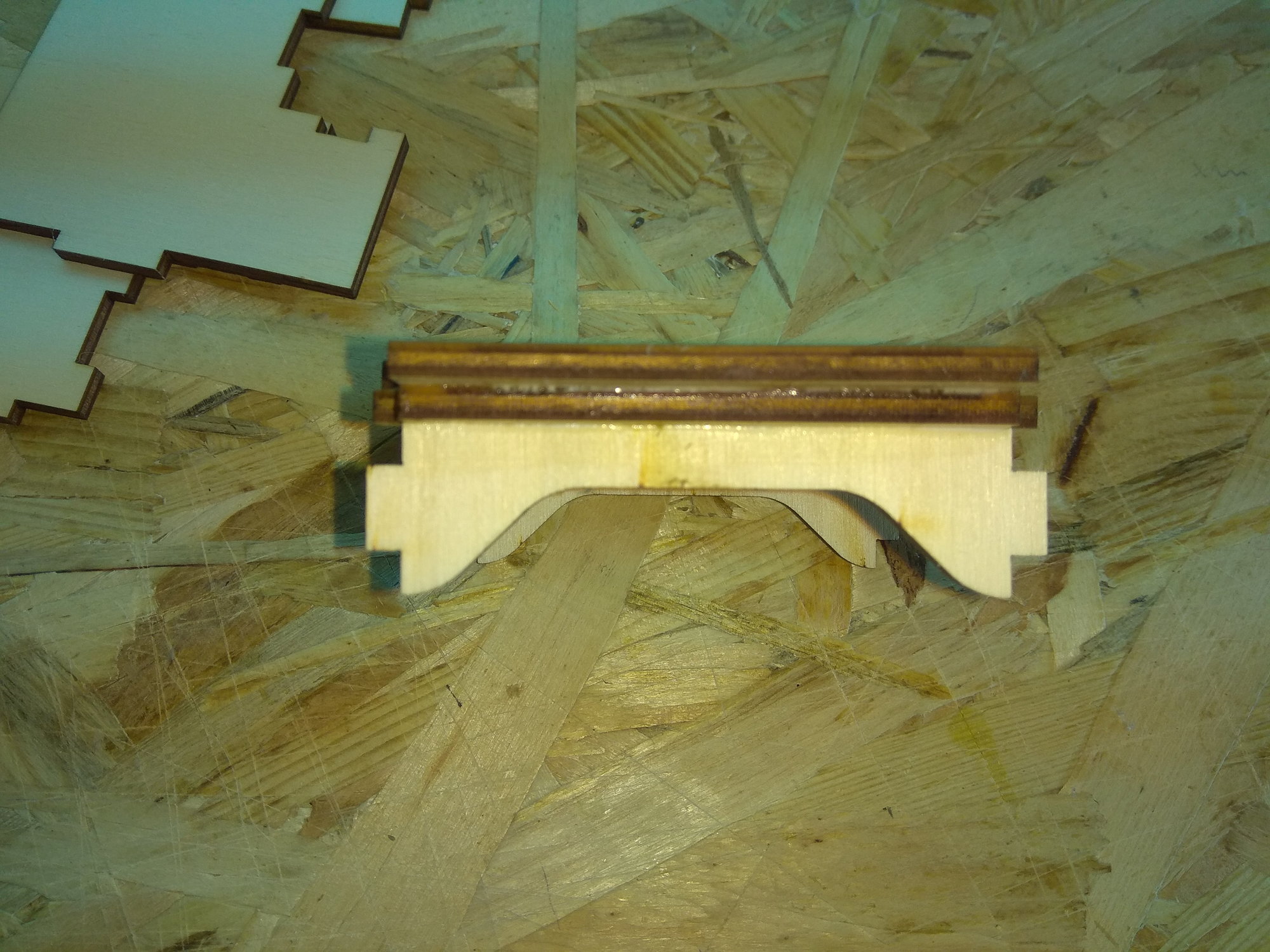
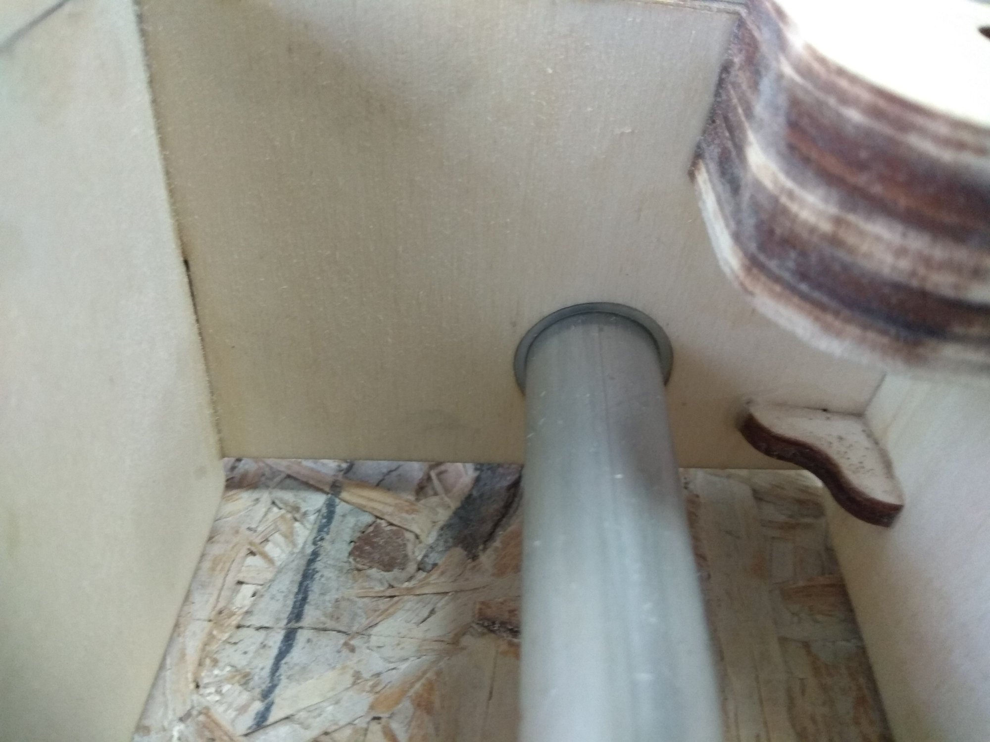
In the workshop, a plastic plug is inserted at the end of the aluminum tube and through it an opening is made, through which the stainless steel tread part passes.Aluminum rings serve not to move the tube (and elevator) to the left - to the right.
Plastic rings are glued into a wooden construction.
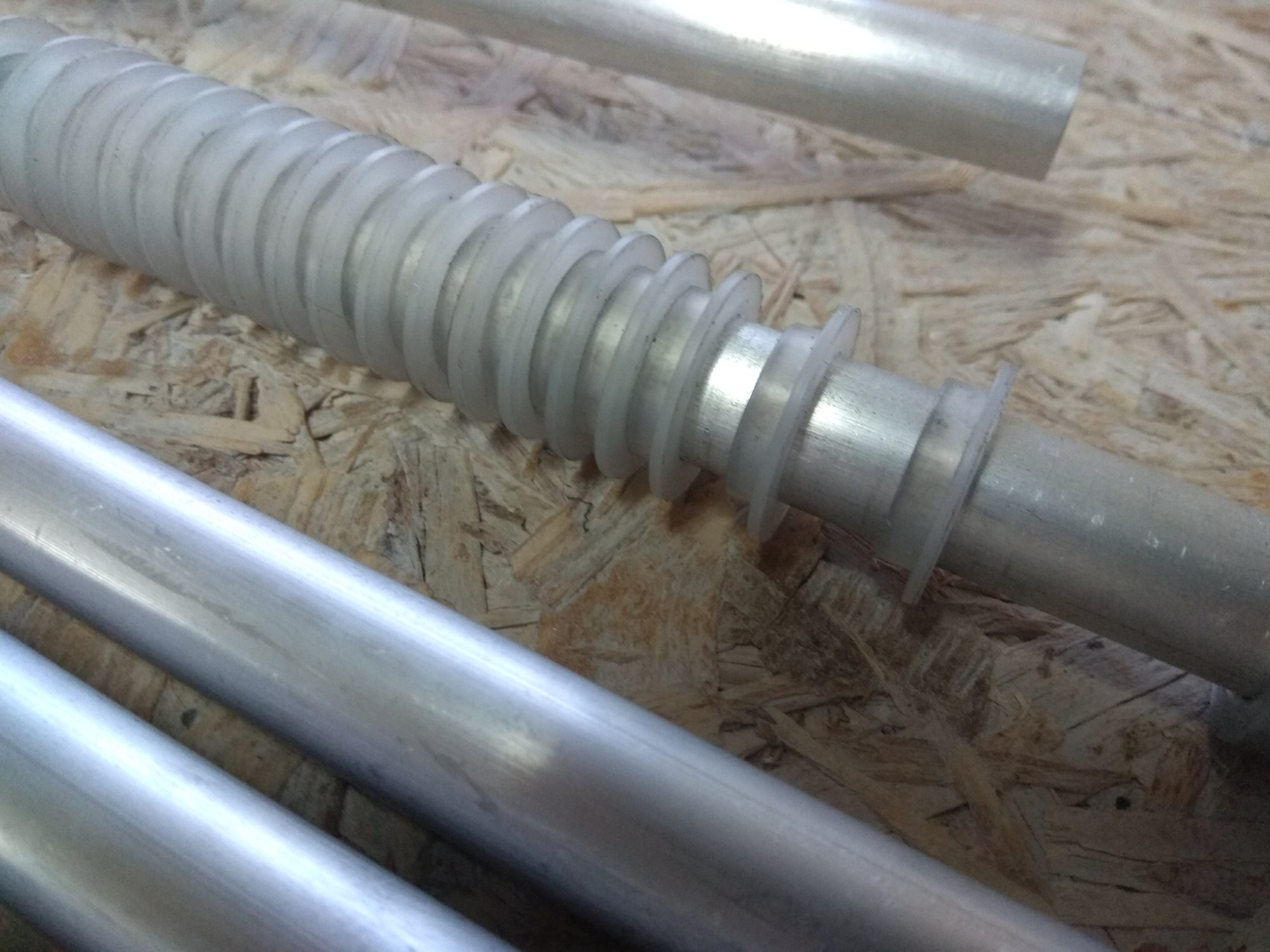

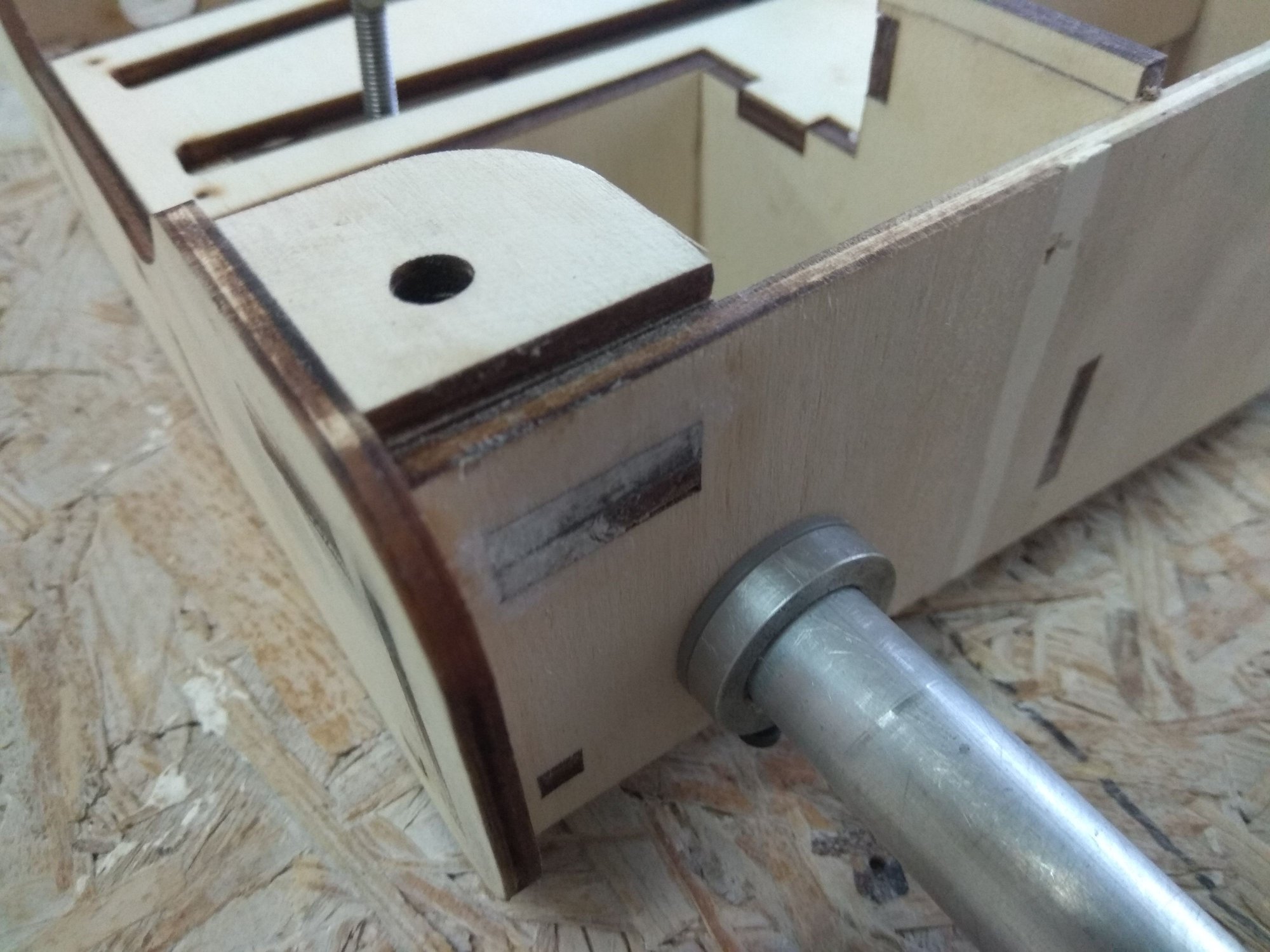

To be continued...
Plastic rings are glued into a wooden construction.
To be continued...
07-07-2018, 12:16 AM
#48
Join Date: Jan 2007
Location: farnborough, , UNITED KINGDOM
Posts: 3,294
Likes: 0
Received 1 Like
on
1 Post
Mirce, I was hoping a gear manufacturer would be watching, when I get round to building Skyfox the gear will be designed to spread loads.
Again nice design on the elevator section, your CAD friend is very good. One suggestion you have the servo tray positioned so the servos sit 'on top' and the linkages to the control horns will be angled through the throw motion, if the servos were mounted 90 degrees to where they are now, fitted into the side of the two frames the linkage would be all in line and less potential for wear or slop, just a suggestion.
marcs
07-13-2018, 10:12 AM
#49
Thread Starter
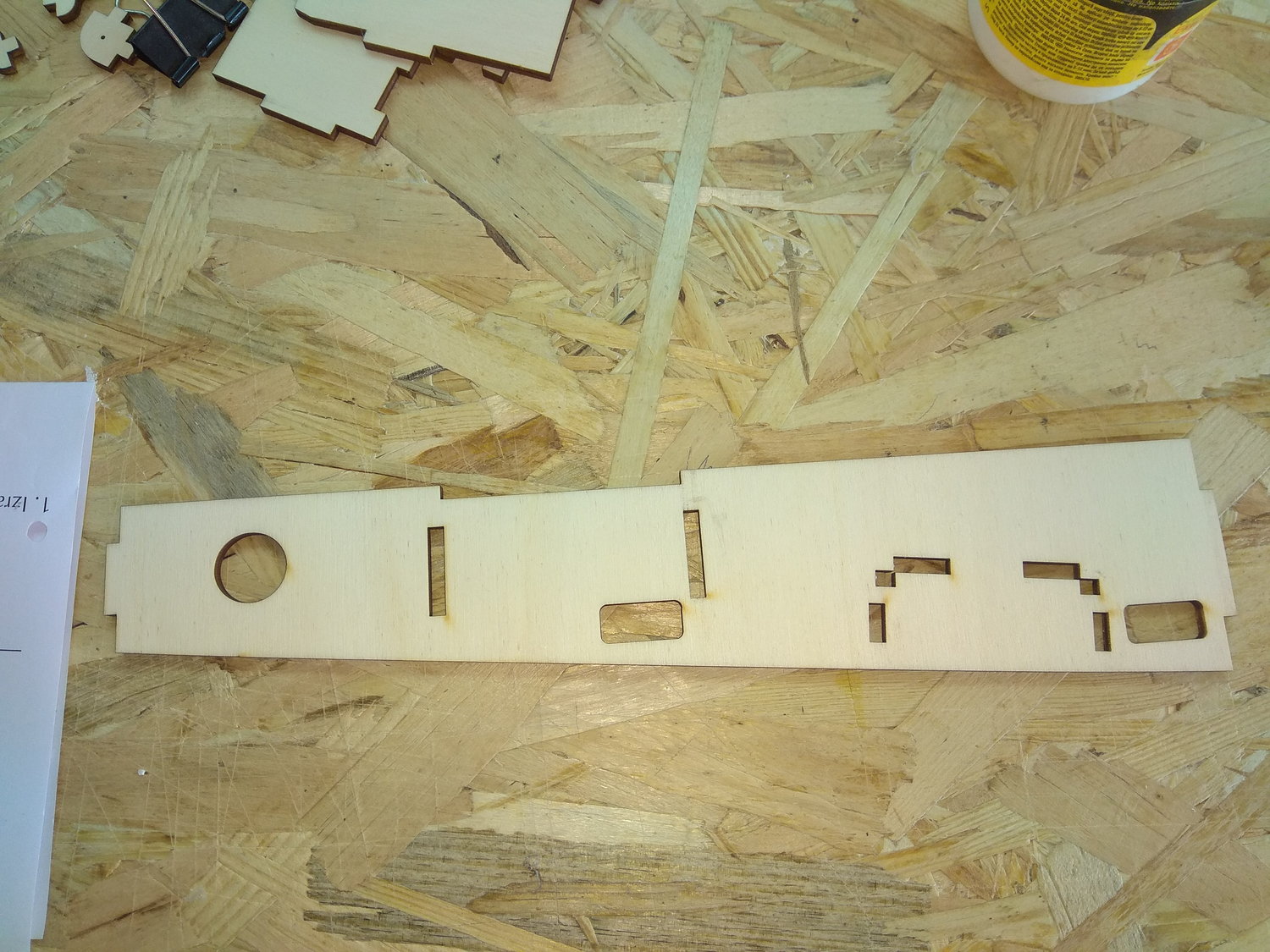
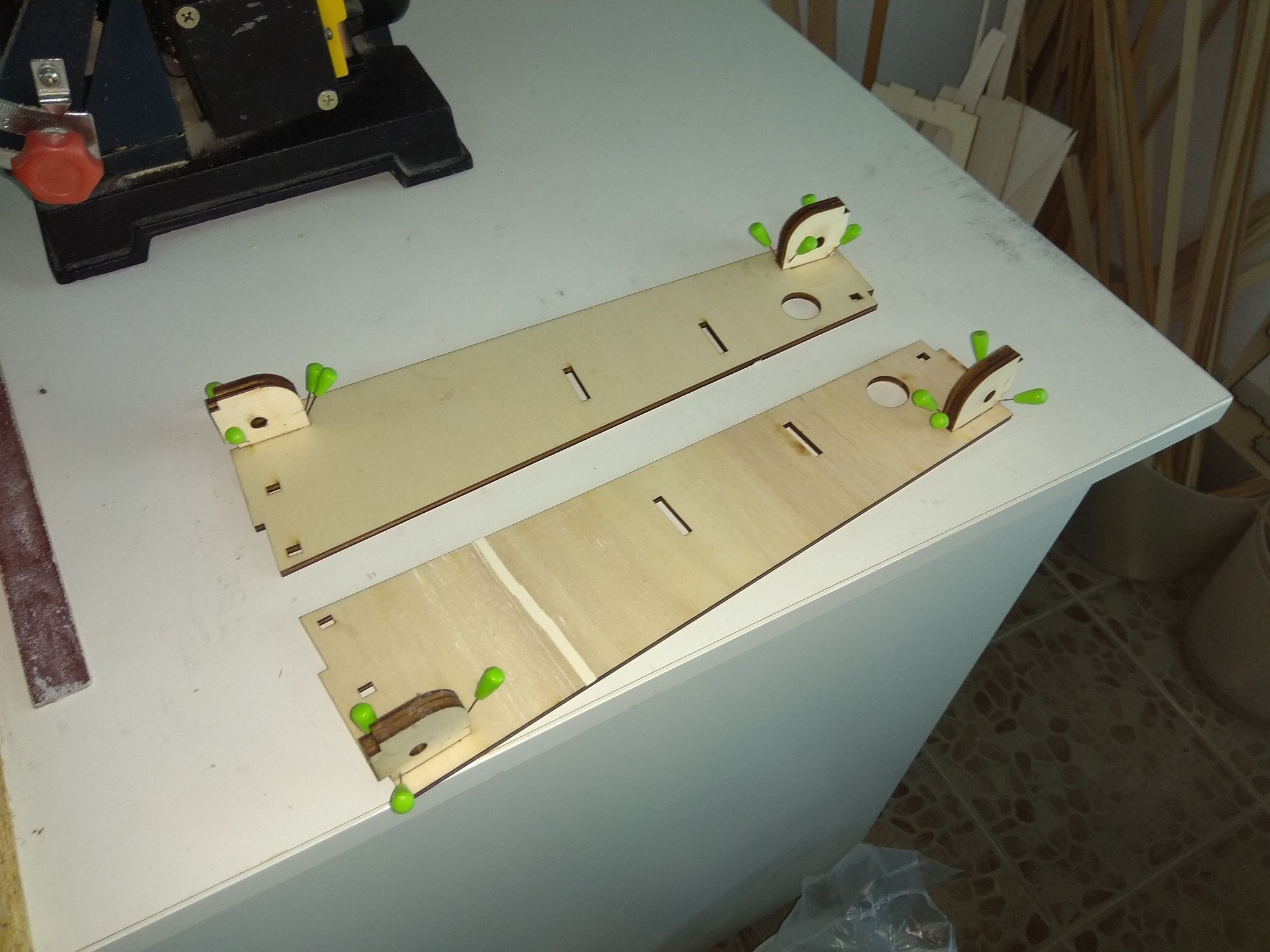
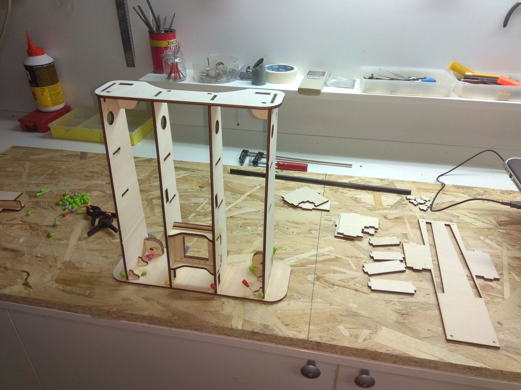
For elevators and rudder I made template for easier assembling. With this ply plates building tail section is "piece of cake"...
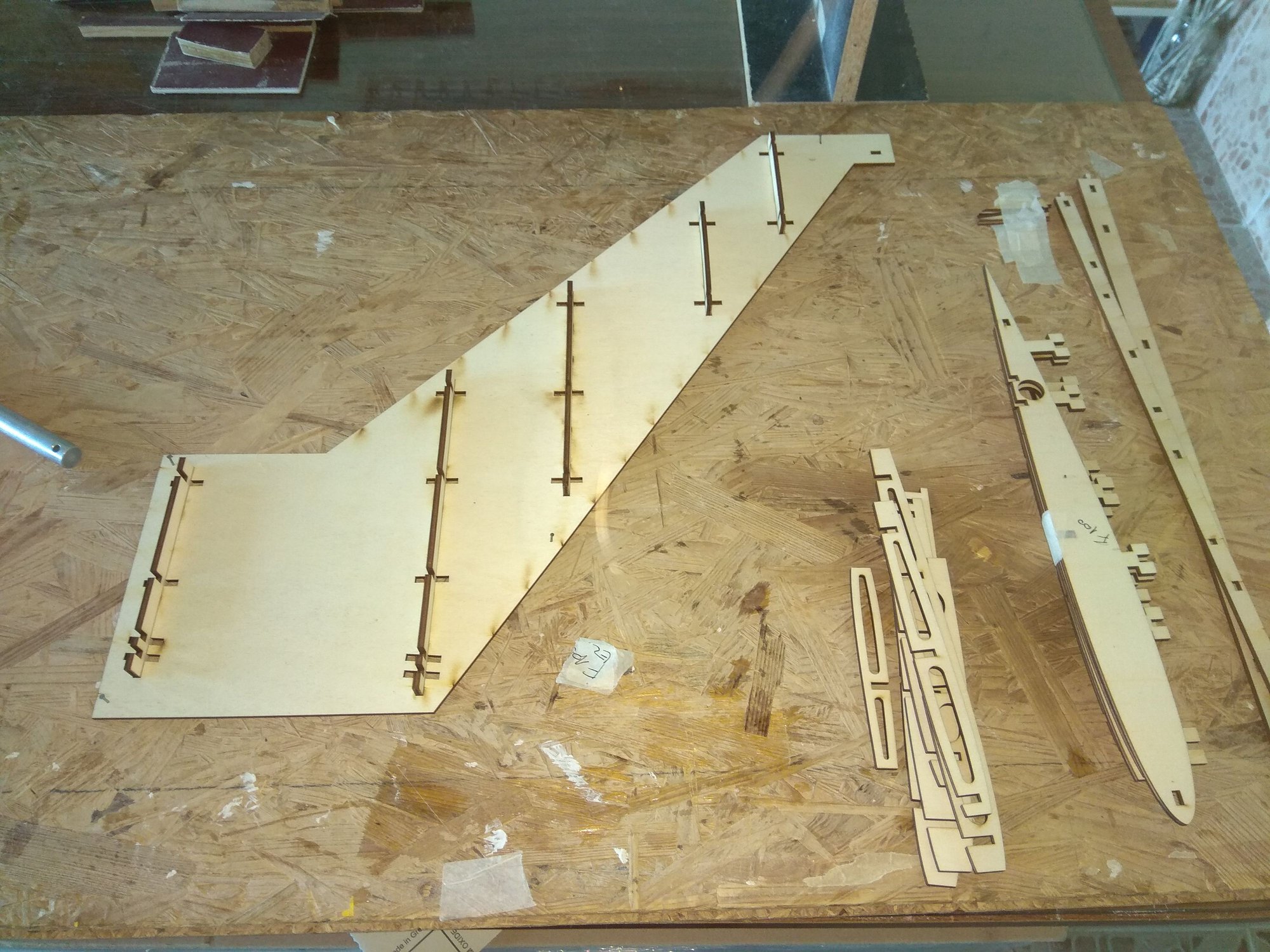
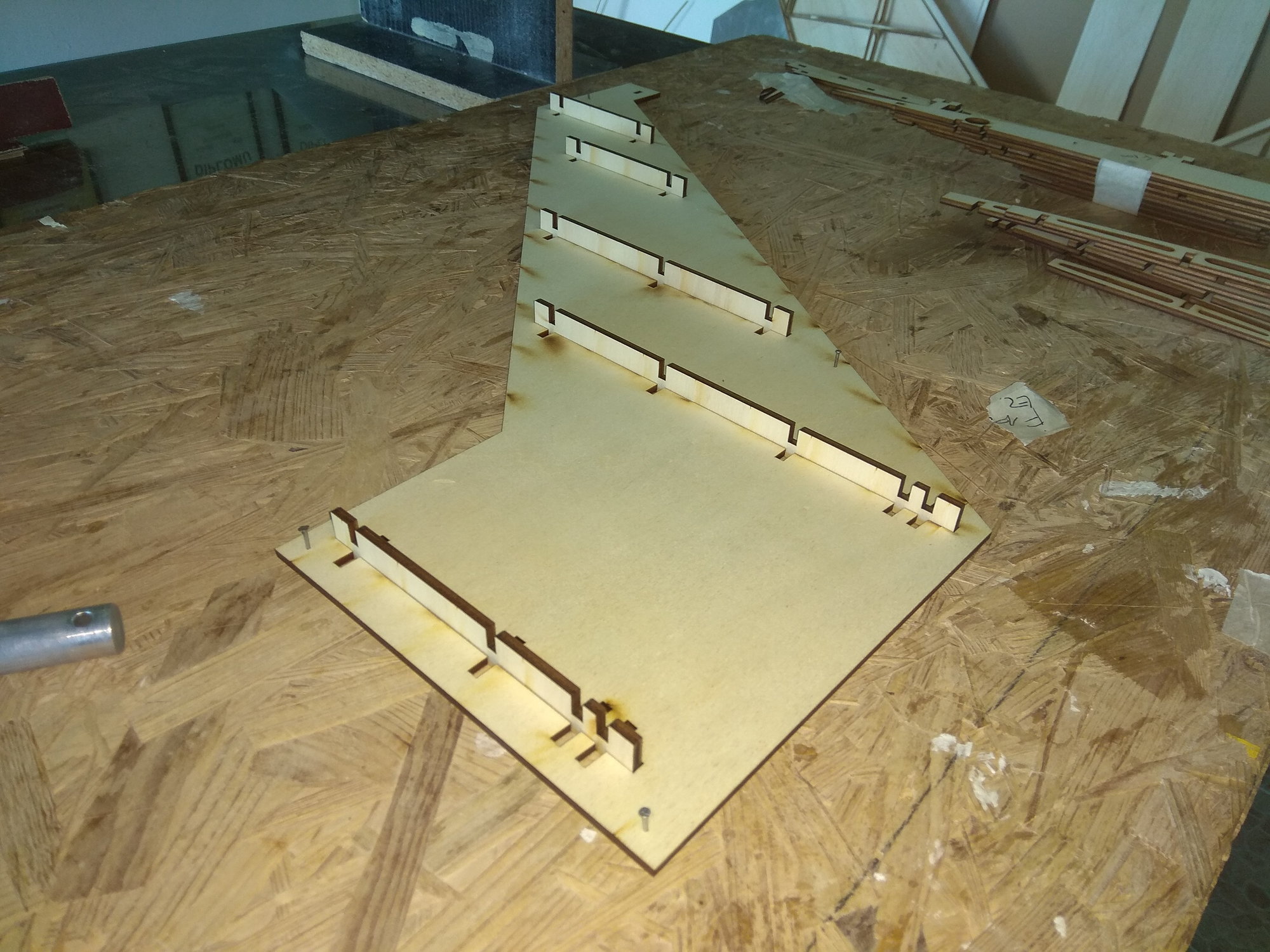


Same story is with rudder, but first, Martin fix rudder drawings, now fin is a right size...

Same story is with rudder, but first, Martin fix rudder drawings, now fin is a right size...