


1/6 F-105 Build Thread
 02-25-2019, 11:23 AM
#376

The two traditional F-105 films are "There is a Way" and "A 25 Hour Day". Both from around 1966-67 or so.
https://www.avgeekery.com/this-f-105...ance-of-thuds/
https://www.avgeekery.com/film-empha...skies-vietnam/
Rosco was still there when I passed thru in '72-'73.
https://www.avgeekery.com/this-f-105...ance-of-thuds/
https://www.avgeekery.com/film-empha...skies-vietnam/
Rosco was still there when I passed thru in '72-'73.
Last edited by Thud_Driver; 02-25-2019 at 11:27 AM.
 02-25-2019, 04:59 PM
#377

Thread Starter
My Feedback: (20)
Appowner, Thank for the compliment. Still plugging ahead.
Paul, I saw that on Amazon also. I may purchase it later.
Thud Driver, Awesome looking videos. I sampled both. Looking forward to looking at them both. I have seen parts of them before on Youtube. The 421st TFS and 388th TFW referenced in "There Is a Way" was my first fighter squadron in 1980 at Hill AFB, UT in the F-16. I was thinking of putting the 421st scheme from Korat on the model to honor the guys who flew the Thuds before my time, Ref my post #13. The videos will really help with documentation.
Not much work last week on the F-105. Too many doctor appointments, spring chores, flat tires, and short week for a local fly in made it too hard to get to it. I also ordered a Freewing 90 mm F-22 to play with so that took some time to research and select power options. Went with a JP Hobbies 8S 1400KV fan. It all came in today so I have a foam box with a chunk of foam shaped like an F-22 inside. This may be my future. Quick, easy, I can pick it up, move it around, and can buy 20 of them for the price of one large scale turbine. Gezzz, let me think...
It will be short week this week too. Going to the Southeast Model Show (giant swap meet) in Perry, GA Thursday for the weekend. Cleaning out the shop of stuff I don't use anymore. Hope to get back to it in March again.
Gary
Last edited by Viper1GJ; 02-25-2019 at 05:12 PM.
 02-25-2019, 08:25 PM
#378

I think you're being a bit hard on Bob Moore. Smooth as a baby's bum is just an expression, it's not a guarantee. What Bob produces isn't a complete kit in the same sense as what a huge company with China production might ship. And even then, there are huge defects with those big companies. FEJ had a honeycomb structure problem for a while. Their gears misplaced an o-ring groove, causing the strut to have a paper thin aluminum section which can break with even a normal landing. Airworld has a landing gear without any positive downlock causing the gear to collapse. They produce hundreds of these kits, and have every opportunity to amortize the cost of fixing defects as they go, yet many don't. Bob Moore's talent is undeniable, just check out his threads on the 16 ft Cessna Citation nearing completion. But it's not realistic, when only 5 are produced, to expect it to go together seamlessly. You're buying a very limited run, custom shell that YOU have to finish. You will be the only one of those at an event, almost guaranteed. Also, you have no idea the work it takes to make those molds, and the cost of the resin and materials that goes into the molds even before he starts to lay up the actual flight airframe. THAT'S why it costs so much. Besides, it costs $4000-$8000 usually for a jet half the size of that F105. So please ease up on Bob Moore. Believe me you are getting what you paid for.
your right.
but that doesnt excuse the fact of simple things like balsa hinge blocks not even touching both skins. Of EVERYTHING involved in doing one of these projects, that is literally the simplist task involved.
02-26-2019, 06:01 PM
#379
Thread Starter
My Feedback: (20)
Looking with interest on the "best-way-get-more-oomph-pneumatic-retracts" thread about the possible use of a hydraulic gear system in case the air wont do the job. Has anyone done that before?
02-27-2019, 06:06 PM
#380
Thread Starter
My Feedback: (20)
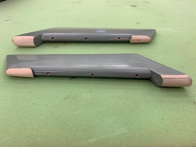
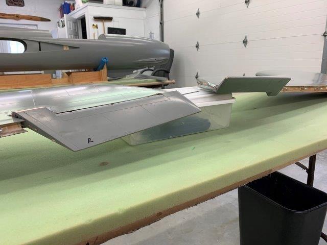
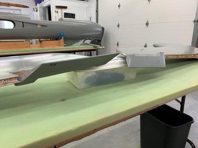
Finally got a little shop time today. Glued flap hinge covers back on flap leading edges.
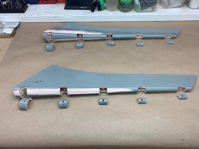
Flap hinge covers ready to glue back into position
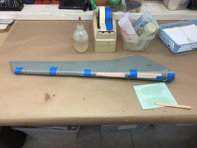
15 min epoxy used
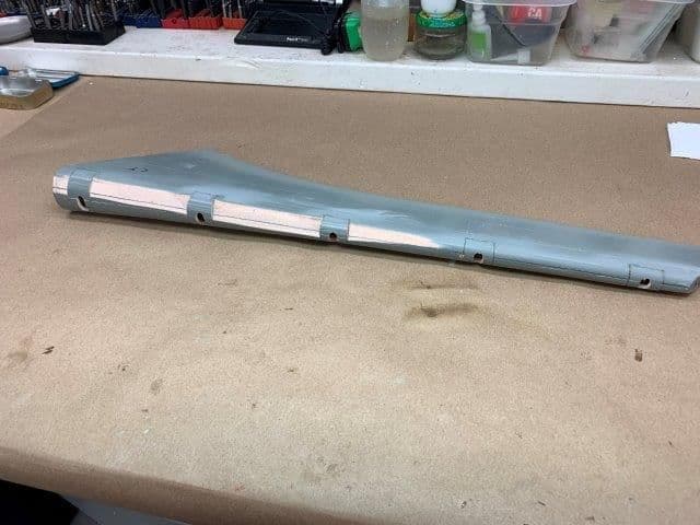
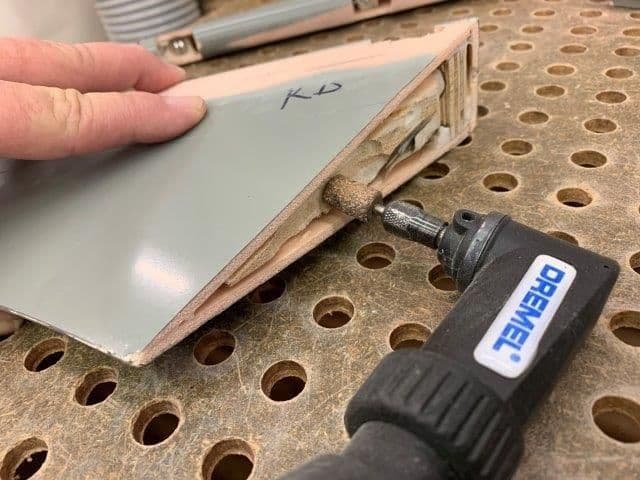
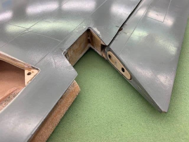
Hinge slots opened up on bottom half of flap with a perma grit dremel grinder. The slots should not show because they are hidden by the gapless hinge design

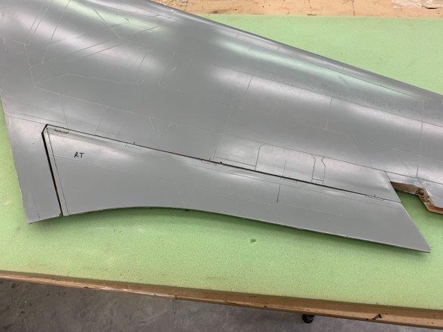
This shows about how much material was removed to make the flaps rotate in the wing trailing edge
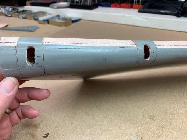
Hinge slots should be completely hidden by the wing trailing edge
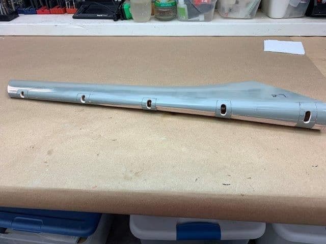
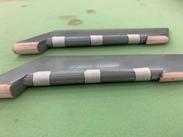
Ready to sand the hinge covers flush with the surface
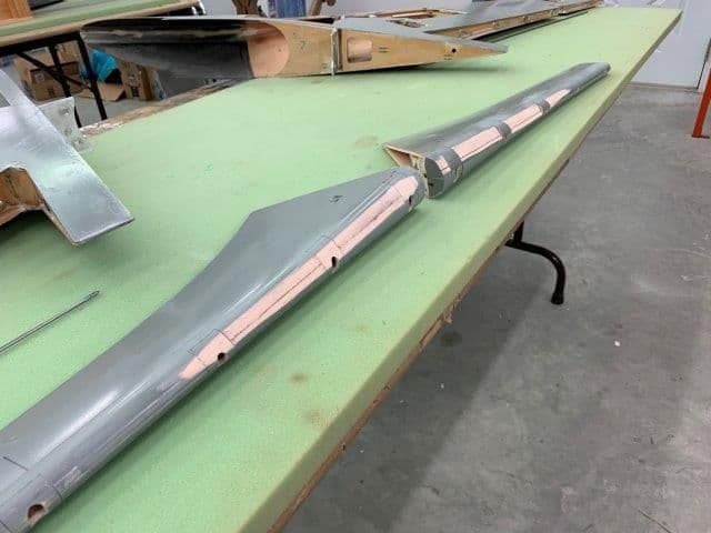
Ran out of time before I got the right flap sanded to shape. Will be next week. Leaving tomorrow for the Southeast Model Show swap meet in Perry GA.
Flap hinge covers ready to glue back into position
15 min epoxy used
Hinge slots opened up on bottom half of flap with a perma grit dremel grinder. The slots should not show because they are hidden by the gapless hinge design
This shows about how much material was removed to make the flaps rotate in the wing trailing edge
Hinge slots should be completely hidden by the wing trailing edge
Ready to sand the hinge covers flush with the surface
Ran out of time before I got the right flap sanded to shape. Will be next week. Leaving tomorrow for the Southeast Model Show swap meet in Perry GA.
03-05-2019, 05:48 PM
#381
Thread Starter
My Feedback: (20)
Had a good trip to the Perry GA swap meet. Sold everything I took and only got one thing to bring home. Got a new Freewing 90mm T-45 EDF foamy for 40% of new price.
Finally got back into shop this week and got started again. Finished flap end caps.
Ground out a recess in flap root end to glue in a screw plate
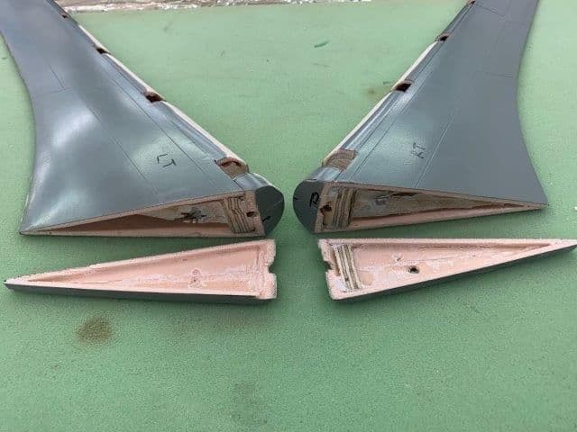
End caps also ground out to glue in a screw plate.
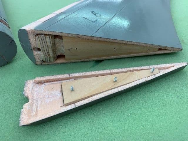
Plywood screw plates installed on both flap and end caps and drilled for servo mounting screws
Screw heads recessed below the surface level of the flap root end cap.
Finally got back into shop this week and got started again. Finished flap end caps.
Ground out a recess in flap root end to glue in a screw plate
End caps also ground out to glue in a screw plate.
Plywood screw plates installed on both flap and end caps and drilled for servo mounting screws
Screw heads recessed below the surface level of the flap root end cap.
Last edited by Viper1GJ; 03-05-2019 at 05:53 PM.
03-05-2019, 06:05 PM
#382
Thread Starter
My Feedback: (20)
Finished the flap hinge wire retainer on both flaps
Plywood insert cut and drilled for hinge wire
Hole for retainer ground out on end of flap
Flap hinge wire retainer fabricated. Screw hole drilled and countersunk with wood block inside flap to catch screw. Plywood CA glued to wire. Hysol applied to wire later.
Wire retainer tap flush with end of flap.
Dry fit before hysol applied to wire
Hysol applied to wire and plywood tabs
Final fit flush with end of flap
Flap hinging done.
03-05-2019, 06:16 PM
#383
Thread Starter
My Feedback: (20)
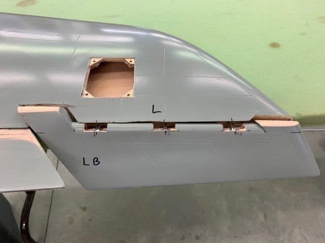
Started hinge work on ailerons
Hinge positions marked, and drilled. You have to use a dremel router bit and thin perma grit grinding shaft to open holes because a drill bit will slide off center because of the hard epoxy splooge inside the seam. I hit wood on the ends but the center missed the wood because the installed wood was not on the center. Have to install a new block for the center hinge.
Used masking tape to mark the cut outs
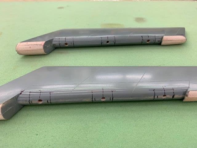
Ready to cut out hinge covers
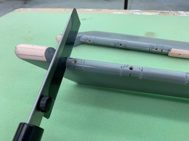
Razor saw and Xacto knife used to remove the hinge covers

Covers removed and ready to clean up the wood and install hinges
Hinge positions marked, and drilled. You have to use a dremel router bit and thin perma grit grinding shaft to open holes because a drill bit will slide off center because of the hard epoxy splooge inside the seam. I hit wood on the ends but the center missed the wood because the installed wood was not on the center. Have to install a new block for the center hinge.
Used masking tape to mark the cut outs
Ready to cut out hinge covers
Razor saw and Xacto knife used to remove the hinge covers
Covers removed and ready to clean up the wood and install hinges
Last edited by Viper1GJ; 03-05-2019 at 06:18 PM.
03-06-2019, 06:08 PM
#384
Thread Starter
My Feedback: (20)
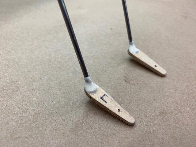
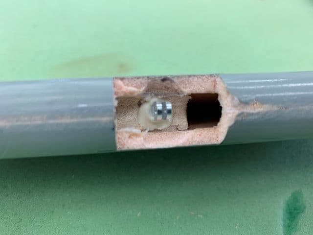
Installed hinge pins in ailerons
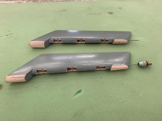
Aileron hinge wire dry fit before hysol applied to hinge pins. I use the finger drill chuck to help turn the wire when inserting and removing for dry fit. I used the same process as before to install the hinge pins in the ailerons. Grinding out a recess deep enough in the wood mounts to allow the wire to go through and not foul the hinge with hysol when glued in. Took about 3 hours of cut, grind, test fit, cut grind, test fit...but it's done.
Hysol applied to holes and hinge pins. Pins inserted and then wire run through them. Adjust for alignment and let it cure.
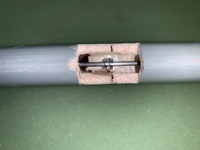
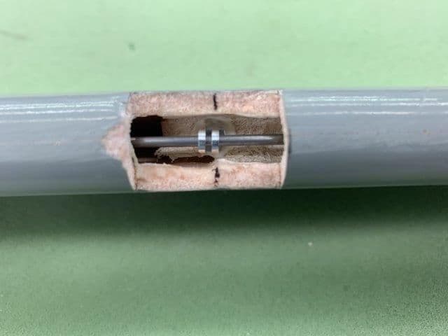
Typical hinge mount, wire, and hysol
Aileron hinge wire dry fit before hysol applied to hinge pins. I use the finger drill chuck to help turn the wire when inserting and removing for dry fit. I used the same process as before to install the hinge pins in the ailerons. Grinding out a recess deep enough in the wood mounts to allow the wire to go through and not foul the hinge with hysol when glued in. Took about 3 hours of cut, grind, test fit, cut grind, test fit...but it's done.
Hysol applied to holes and hinge pins. Pins inserted and then wire run through them. Adjust for alignment and let it cure.
Typical hinge mount, wire, and hysol
03-06-2019, 06:27 PM
#385
Thread Starter
My Feedback: (20)
Moved to rudder control horn while waiting for hysol to cure on aileron hinge pins.
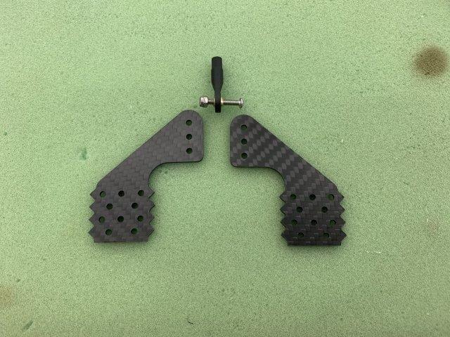
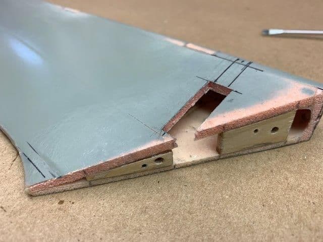
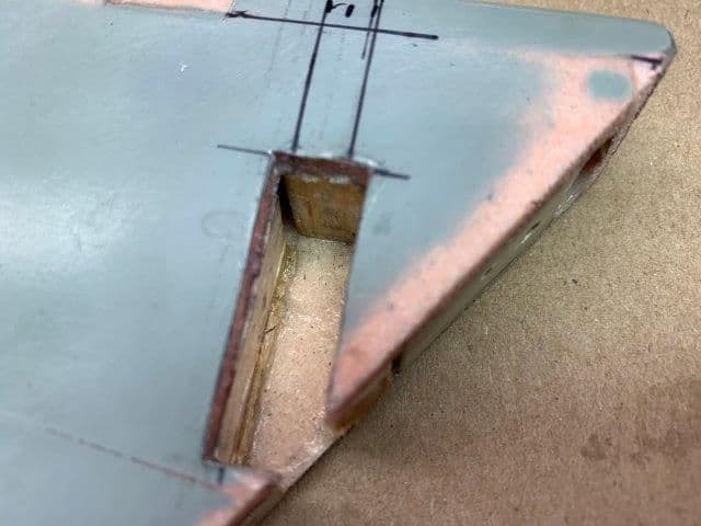
Elected to use these large CF dual horns from Booma RC for all the surfaces. Comes with ball link and bolt. I computed the servo torque requirements for the rudder using a 1.5" control horn. Spent some time to figure how to cut the bottom to get the correct position and distance over the hinge line.

Plotting location of control horn hole in rudder
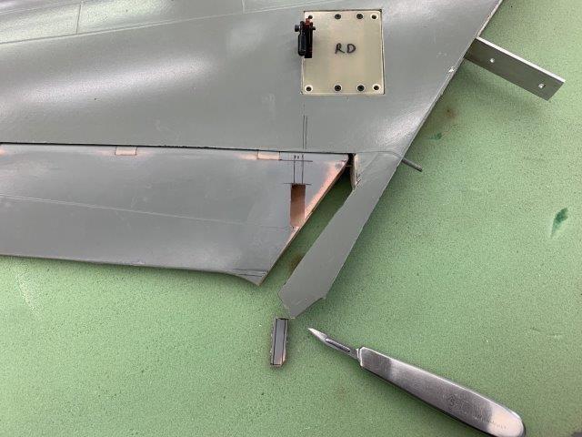
Hole cut with scalpel blade.

CF horns cut to shape with dremel cut off wheel and dust collector to keep dust under control. You have to hold on to the horn after cutting or guess where it goes! Ask me how I know. Lucky it got stuck in hose and did not go through the impeller fan.
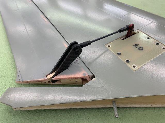
Dry fit test mock up using a plastic cotton swap stick and 3/16" balsa between the horn arms.

Rear view.
Elected to use these large CF dual horns from Booma RC for all the surfaces. Comes with ball link and bolt. I computed the servo torque requirements for the rudder using a 1.5" control horn. Spent some time to figure how to cut the bottom to get the correct position and distance over the hinge line.
Plotting location of control horn hole in rudder
Hole cut with scalpel blade.
CF horns cut to shape with dremel cut off wheel and dust collector to keep dust under control. You have to hold on to the horn after cutting or guess where it goes! Ask me how I know. Lucky it got stuck in hose and did not go through the impeller fan.
Dry fit test mock up using a plastic cotton swap stick and 3/16" balsa between the horn arms.
Rear view.
Last edited by Viper1GJ; 03-06-2019 at 06:46 PM.
03-06-2019, 06:39 PM
#386
Thread Starter
My Feedback: (20)
Gluing rudder horn into rudder
Rudder has no wood block to mount horn into so I reversed engineered a wood box to glue the horn into.
Used 1/4"balsa to line the hole to give the horns something to grip to.
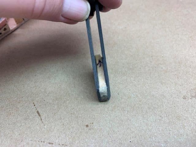
3/16" balsa CA glued inside horn halves.
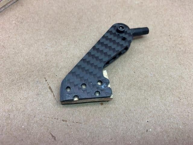
CA penetrated holes in the CF and balsa and turned the whole assemble to a very ridged control horn
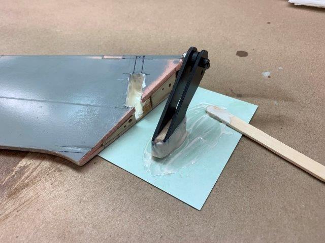
Hysol applied to all parts. I used the stick to force the hysol into all the cracks and voids

Final position after clean up of hysol squeeze out. A weighted Phillips screwdriver used to hold the horn in place during cure.

Rudder control horn done.
Rudder has no wood block to mount horn into so I reversed engineered a wood box to glue the horn into.
Used 1/4"balsa to line the hole to give the horns something to grip to.
3/16" balsa CA glued inside horn halves.
CA penetrated holes in the CF and balsa and turned the whole assemble to a very ridged control horn
Hysol applied to all parts. I used the stick to force the hysol into all the cracks and voids
Final position after clean up of hysol squeeze out. A weighted Phillips screwdriver used to hold the horn in place during cure.
Rudder control horn done.
Last edited by Viper1GJ; 03-07-2019 at 05:13 PM.
03-07-2019, 05:44 PM
#387
Thread Starter
My Feedback: (20)
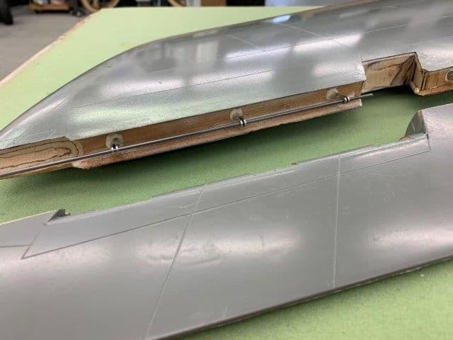
Aileron hinges glued into wings
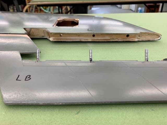
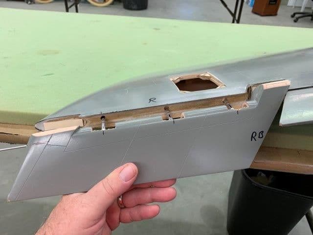
Spent several hours setting up aileron hinge pins for the wings. I started by marking and drilling the holes in the wing trailing edge. The hinge pins were cut shorter to make install possible. With the full hinge pin length it was impossible to get them in the holes. Only about 3/8" is actually in contact with the trailing edge anyway. The holes had to be reamed and shaped several times to make the hinges not bind.
After getting the pins to go in the wing I realized each hinge opening had to have the airex foam ground away around the hinge pin to allow full aileron travel.
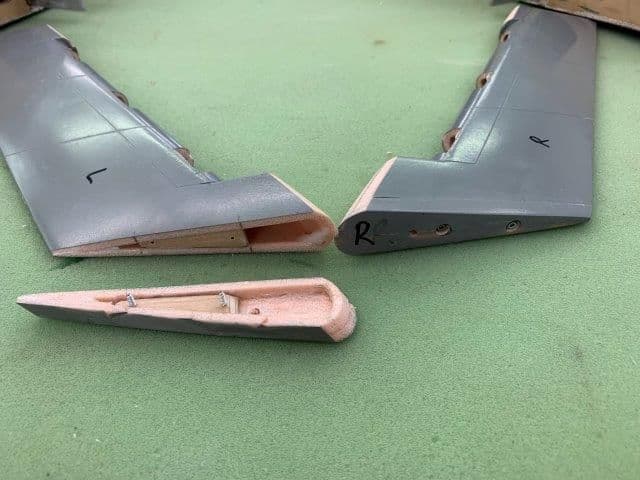
I was hoping not to have to cut the root end off to get the ailerons on and off the hinges but there was no way. The aileron must move out about 5mm to disengage the hinge pin forks after the wire is removed. This was impossible with out cutting off the root end of the ailerons. After trying for an hour every possible angle and dangle to get them on and off, I finally gave in and made the cuts.
After finally removing the root end of the aileron it was easy to fit. Here I'm rehearsing the moves needed to install the hinge pins in the wing before the hysol was applied. After lining everything up it was possible to insert the hinge pins all together and push them in while rotating the aileron up to the level position. I installed some spacers on the wing trailing edge to keep from pushing the hinges in too far.
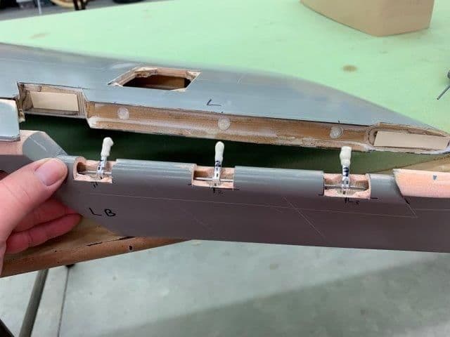
The moment of truth. You get one chance to do this right or it becomes a mess. I got lucky on both ailerons.
Both ailerons installed and hysol curing. Hopefully they will move tomorrow. The flaps didn't. We will see.
Spent several hours setting up aileron hinge pins for the wings. I started by marking and drilling the holes in the wing trailing edge. The hinge pins were cut shorter to make install possible. With the full hinge pin length it was impossible to get them in the holes. Only about 3/8" is actually in contact with the trailing edge anyway. The holes had to be reamed and shaped several times to make the hinges not bind.
After getting the pins to go in the wing I realized each hinge opening had to have the airex foam ground away around the hinge pin to allow full aileron travel.
I was hoping not to have to cut the root end off to get the ailerons on and off the hinges but there was no way. The aileron must move out about 5mm to disengage the hinge pin forks after the wire is removed. This was impossible with out cutting off the root end of the ailerons. After trying for an hour every possible angle and dangle to get them on and off, I finally gave in and made the cuts.
After finally removing the root end of the aileron it was easy to fit. Here I'm rehearsing the moves needed to install the hinge pins in the wing before the hysol was applied. After lining everything up it was possible to insert the hinge pins all together and push them in while rotating the aileron up to the level position. I installed some spacers on the wing trailing edge to keep from pushing the hinges in too far.
The moment of truth. You get one chance to do this right or it becomes a mess. I got lucky on both ailerons.
Both ailerons installed and hysol curing. Hopefully they will move tomorrow. The flaps didn't. We will see.
03-08-2019, 06:29 PM
#388
Thread Starter
My Feedback: (20)
Well the next morning... the ailerons moved but just barely.
Hinge pins were all well glued in and no hysol was on hinges but ailerons were very stiff. There was no rubbing on the wing like the flaps so the problem was the hinges.
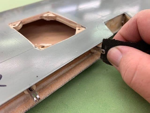
The hinges have a very tight tolerance between the slots and any offset caused binding. I had to open the slots up slightly with some sand paper. This took a while.
I also reamed out the holes with the wire technique used on the flaps. I had to open up the counter weight cut out in the trailing edge of the wing to get full deflection of the aileron.
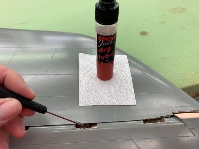
The last step was to use a drop of BVM dry lube on the hinges and now there is almost no friction when moving the aileron.
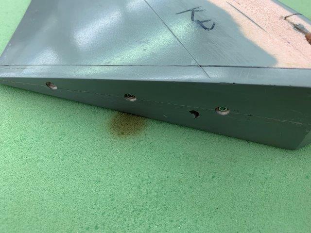
The end caps were installed like the flaps using some plywood mounts and servo screws recessed below the surface.
We now have full aileron deflection with very little friction.
And the opposite direction.
Hinge pins were all well glued in and no hysol was on hinges but ailerons were very stiff. There was no rubbing on the wing like the flaps so the problem was the hinges.
The hinges have a very tight tolerance between the slots and any offset caused binding. I had to open the slots up slightly with some sand paper. This took a while.
I also reamed out the holes with the wire technique used on the flaps. I had to open up the counter weight cut out in the trailing edge of the wing to get full deflection of the aileron.
The last step was to use a drop of BVM dry lube on the hinges and now there is almost no friction when moving the aileron.
The end caps were installed like the flaps using some plywood mounts and servo screws recessed below the surface.
We now have full aileron deflection with very little friction.
And the opposite direction.
03-08-2019, 06:50 PM
#389
Thread Starter
My Feedback: (20)
Aileron final fitting.
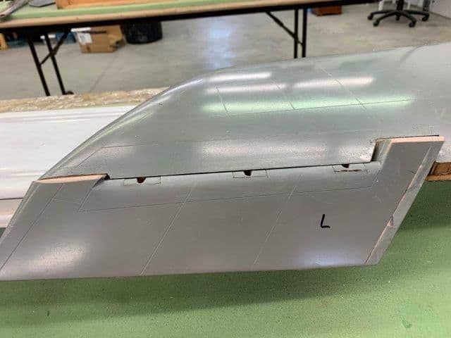
The hinge caps were glued back on the leading edge and sanded smooth. The hinge slots were enlarged to allow full movement up and down.
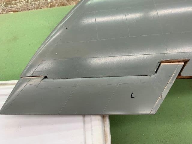
The hinge slots are not visible when aileron is at neutral. The dents and sanding on the end cap was an OOPS. When fitting the plywood screw mounts I accidentally allowed the cap to slip into the dust collector hose and bang...it went thru the impeller and into the hopper bag. I dug it out (a real sawdust mess) and repaired the dents. It will need some more work.
The aileron was about 3/16" shorter than the wing tip. I added a balsa strip and sanded to rough shape.
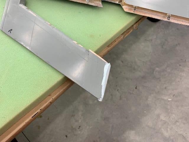
Icing light weight body filler curing waiting to sand.
I elected to do this body work now because I need the aileron tip the correct size so I can fabricate the hinge wire retainer on the end of the aileron.
The hinge caps were glued back on the leading edge and sanded smooth. The hinge slots were enlarged to allow full movement up and down.
The hinge slots are not visible when aileron is at neutral. The dents and sanding on the end cap was an OOPS. When fitting the plywood screw mounts I accidentally allowed the cap to slip into the dust collector hose and bang...it went thru the impeller and into the hopper bag. I dug it out (a real sawdust mess) and repaired the dents. It will need some more work.
The aileron was about 3/16" shorter than the wing tip. I added a balsa strip and sanded to rough shape.
Icing light weight body filler curing waiting to sand.
I elected to do this body work now because I need the aileron tip the correct size so I can fabricate the hinge wire retainer on the end of the aileron.
03-11-2019, 05:42 PM
#390
Thread Starter
My Feedback: (20)
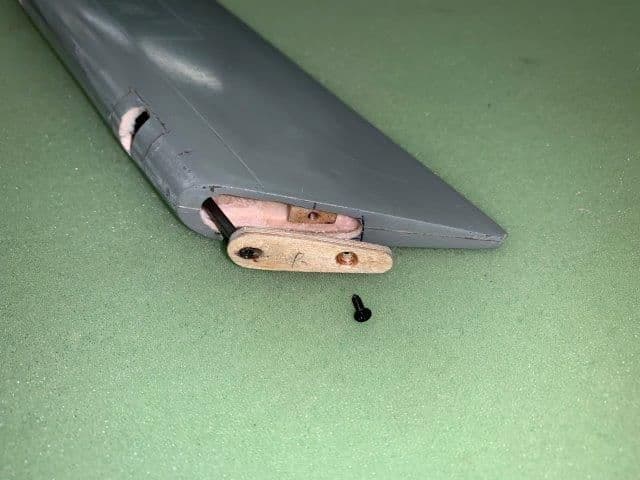
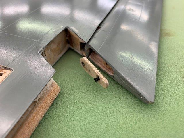
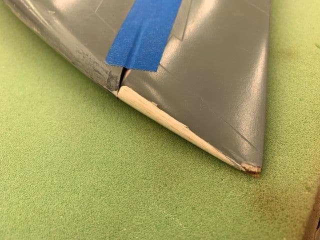
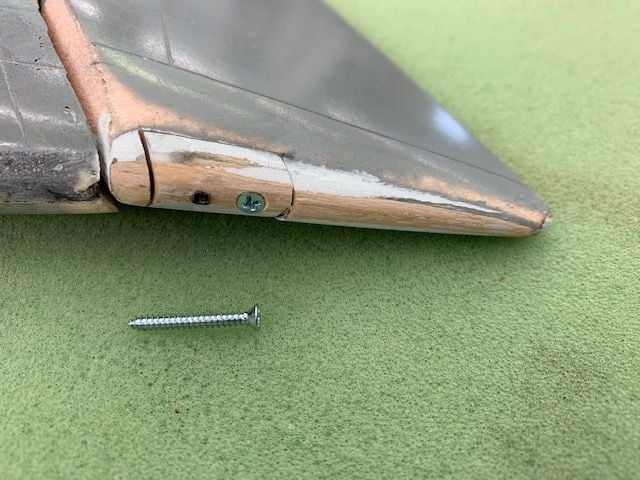
Aileron hinging finished!
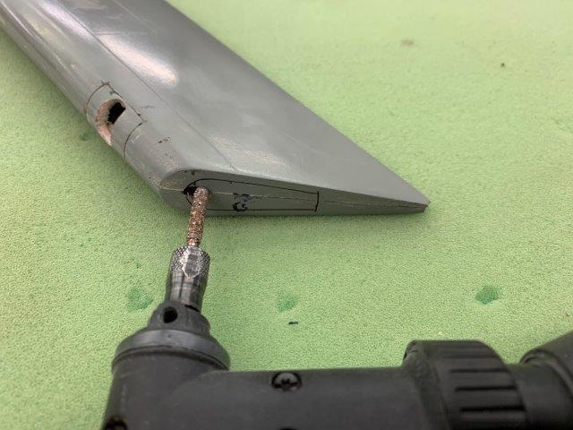
Aileron tips extended to match the wing tips and sanded to shape.
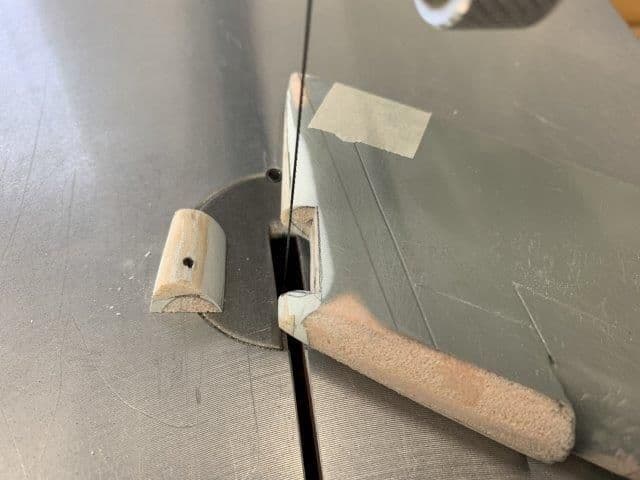
Small cut out made with scroll saw to attach the hinge wire.
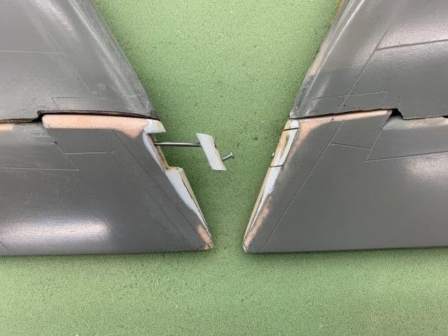
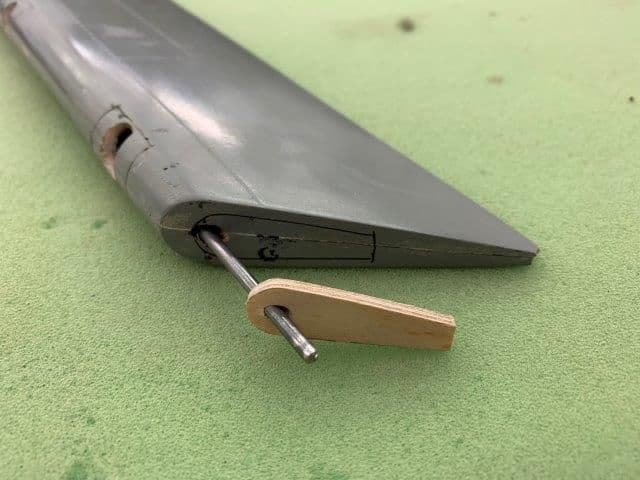
Hinge wire glued into the block and screw used to secure the block to aileron tip.
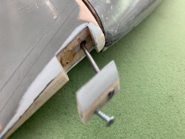
A small block of wood was glued inside the aileron to catch the screw.
Aileron hinge wire secured to aileron tip. Button head screw is a temp. I will countersink the screw head flush with the tip when I get the proper #2 x 3/4" flat head screws and then sand the tip to final shape.
Aileron tips extended to match the wing tips and sanded to shape.
Small cut out made with scroll saw to attach the hinge wire.
Hinge wire glued into the block and screw used to secure the block to aileron tip.
A small block of wood was glued inside the aileron to catch the screw.
Aileron hinge wire secured to aileron tip. Button head screw is a temp. I will countersink the screw head flush with the tip when I get the proper #2 x 3/4" flat head screws and then sand the tip to final shape.
Last edited by Viper1GJ; 03-11-2019 at 05:45 PM.
03-11-2019, 05:57 PM
#391
Thread Starter
My Feedback: (20)
Felt some relief today.
I felt like I finally turned a corner in the F-105 build today by finishing the flight control hinging. This is the last process I think that has to be engineered or re-engineered to to figure out how it will work. The rest of the project has several tedious tasks left like gear doors, canopy, engine hatch, fuel tank, pitot tube, etc but this is just normal model airplane work. There is no mystery or unknowns, just have to plug thru it. I think we have solved most of the "how do I do this now" stuff and the rest of the build will be just normal jet stuff. So far I,m happy with how it seems to be going.
Thank you again for all help and suggestions from everybody getting it this far.
More to come,
Gary
03-18-2019, 04:23 PM
#392
Thread Starter
My Feedback: (20)
Took last week off from F-105 work to get ready for the Jason Jordan Jet Jam in Piedmont, SC.
I had previously ordered a Freewing F-22 90 mm EDF which was still in the box. Also I picked up a barely used Feewing T-45 90 mm EDF at the swap meet in Perry, GA. So I got the foamie fleet ready to go last week. Got the camper woke up from winter nap today and packing tomorrow. Departing for the jet meet Wednesday for the weekend.
Hope to get back to the F-105 next week. Looking forward to getting back to it after having some time to think through how proceed next.
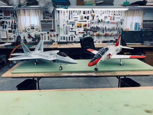
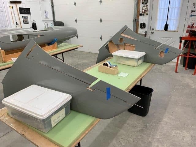
Foamie fleet ready to fly!
I had previously ordered a Freewing F-22 90 mm EDF which was still in the box. Also I picked up a barely used Feewing T-45 90 mm EDF at the swap meet in Perry, GA. So I got the foamie fleet ready to go last week. Got the camper woke up from winter nap today and packing tomorrow. Departing for the jet meet Wednesday for the weekend.
Hope to get back to the F-105 next week. Looking forward to getting back to it after having some time to think through how proceed next.
Foamie fleet ready to fly!
03-26-2019, 05:44 PM
#393
Thread Starter
My Feedback: (20)
The Jason Jordan Jet Jam was a great meet. Great weather and good friends. A fitting memorial ceremony for Jason Jordon was held Friday night with a proper fighter squadron piano burning. No shop time this week due to spring chores and family visit through the weekend.
I got a drag chute from my friend Frank Alvarez and now I'm looking for a drag chute deployment system for the F-105 like the AutoChute from Details 4 Scale. Does anybody know if these systems are available now and where to get one.
Thanks,
Gary
I got a drag chute from my friend Frank Alvarez and now I'm looking for a drag chute deployment system for the F-105 like the AutoChute from Details 4 Scale. Does anybody know if these systems are available now and where to get one.
Thanks,
Gary
04-18-2019, 03:57 PM
#394
Thread Starter
My Feedback: (20)
Well I finally got back to the F-105 today. Spring chores, flying season, and family trips took up the last 5 weeks and the project sat in the corner. Last week was the Carolina Jet Fest in Scranton, SC, and even with the rain and wind was a fun time. Mostly caught up on house and yard chores now so I started at it again today.
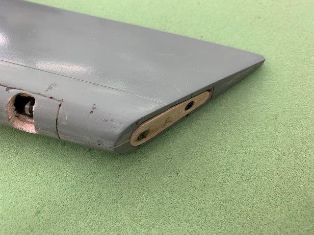
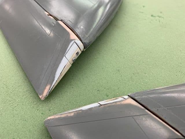
Finally got the flat head screws to secure aileron hinge wires into the wing tips. Countersunk the holes and screws are flush now.
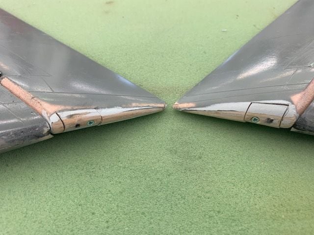
Tip of both ailerons.
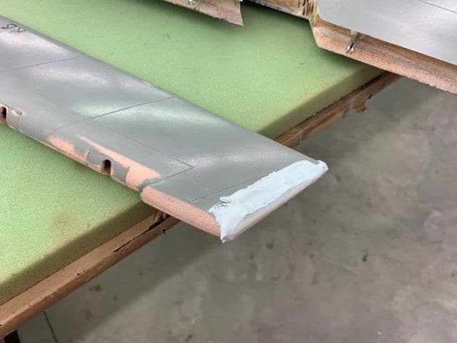
Applied light weight body putty to the sanded areas of the flaps and ailerons. I plan to sand smooth and apply lightweight glass to the sanded areas and reprime.
Finally got the flat head screws to secure aileron hinge wires into the wing tips. Countersunk the holes and screws are flush now.
Tip of both ailerons.
Applied light weight body putty to the sanded areas of the flaps and ailerons. I plan to sand smooth and apply lightweight glass to the sanded areas and reprime.
Last edited by Viper1GJ; 04-18-2019 at 04:01 PM.
04-19-2019, 02:42 AM
#395
Join Date: Sep 2013
Posts: 631
Likes: 0
Received 0 Likes
on
0 Posts
Well I finally got back to the F-105 today. Spring chores, flying season, and family trips took up the last 5 weeks and the project sat in the corner. Last week was the Carolina Jet Fest in Scranton, SC, and even with the rain and wind was a fun time. Mostly caught up on house and yard chores now so I started at it again today.
Finally got the flat head screws to secure aileron hinge wires into the wing tips. Countersunk the holes and screws are flush now.
Tip of both ailerons.
Applied light weight body putty to the sanded areas of the flaps and ailerons. I plan to sand smooth and apply lightweight glass to the sanded areas and reprime.
The pink foam look like normal foam not airex! is strong enough?! 😊
04-19-2019, 04:17 AM
#396

Amazing project and kudos to you Gary for an epic level of documenting and photographing your progress on this thread. It is seriously like a professional caliber manual for this jet. Amazing!!
04-19-2019, 04:31 PM
#397
Thread Starter
My Feedback: (20)
Mugu, I don't know what the pink material is. It may not be airex, that is just what I called it. It is some kind of composite core material. You can see Bob lay it up in his videos. It seems to be quite stiff and strong as a core material between the two fiberglass skins. It sands easily and holds its shape well and the parts are very strong using it.
Flyloose, thanks for the compliment. Its just part of the fun for me to take the pics and post stuff. Not sure how many are reading but I have received lots of valuable help from some on the forum. Many thanks again to all who have helped and suggested.
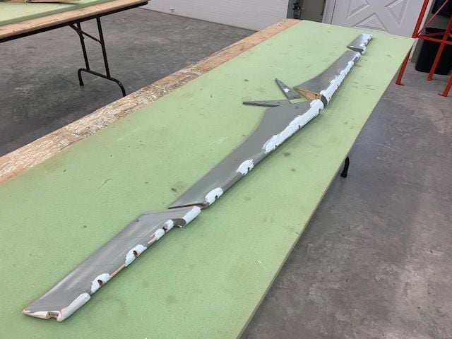
I wanted to get the sanding of the flight controls done and install control horns today. Mother nature had different ideas. I just got the sanding done and then a squall line of thunderstorms rolled through South Carolina and took out the power. So much for shop time to day. Its still off now even as I write this. I've got my flight line generator running the refrigerator, TV, and computer. Hopefully better luck tomorrow.
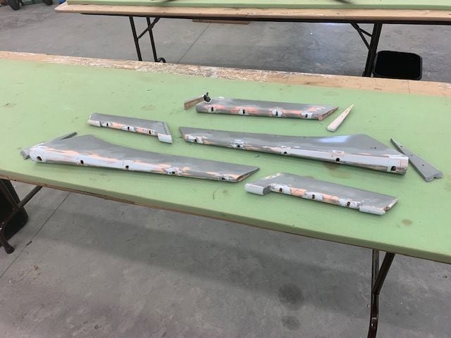
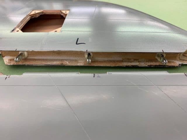
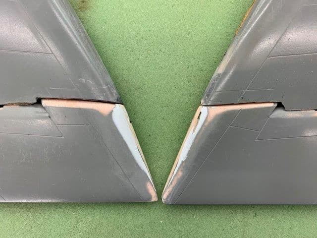
This is as far as I got before the power failed after three hours of sanding. I don't think I will need to glass the parts again. Everything looks good and has a hard surface so I think a good coat of 2K primer will be ok. Most of the sanded areas will be hidden inside the gapless hinge area of the wing anyway.
Next step is to install control horns. The ailerons will be straight forward with the servos mounted on the servo well hatch. That is bad geometry for the flaps as it puts all the flap air loads into the servo when extended. I want to look at lowering the servo into the wing to get the servo arm nearly inline with the flap pushrod when flaps are fully extended. That will require redesigning the flap servo mount. We will see.
Flyloose, thanks for the compliment. Its just part of the fun for me to take the pics and post stuff. Not sure how many are reading but I have received lots of valuable help from some on the forum. Many thanks again to all who have helped and suggested.
I wanted to get the sanding of the flight controls done and install control horns today. Mother nature had different ideas. I just got the sanding done and then a squall line of thunderstorms rolled through South Carolina and took out the power. So much for shop time to day. Its still off now even as I write this. I've got my flight line generator running the refrigerator, TV, and computer. Hopefully better luck tomorrow.
This is as far as I got before the power failed after three hours of sanding. I don't think I will need to glass the parts again. Everything looks good and has a hard surface so I think a good coat of 2K primer will be ok. Most of the sanded areas will be hidden inside the gapless hinge area of the wing anyway.
Next step is to install control horns. The ailerons will be straight forward with the servos mounted on the servo well hatch. That is bad geometry for the flaps as it puts all the flap air loads into the servo when extended. I want to look at lowering the servo into the wing to get the servo arm nearly inline with the flap pushrod when flaps are fully extended. That will require redesigning the flap servo mount. We will see.
04-20-2019, 04:52 PM
#400
Thread Starter
My Feedback: (20)
How is your T-38 coming along?
Gary
Last edited by Viper1GJ; 04-20-2019 at 04:56 PM.