


1/6 F-105 Build Thread
 09-22-2019, 06:25 AM
#476

Thread Starter
My Feedback: (20)
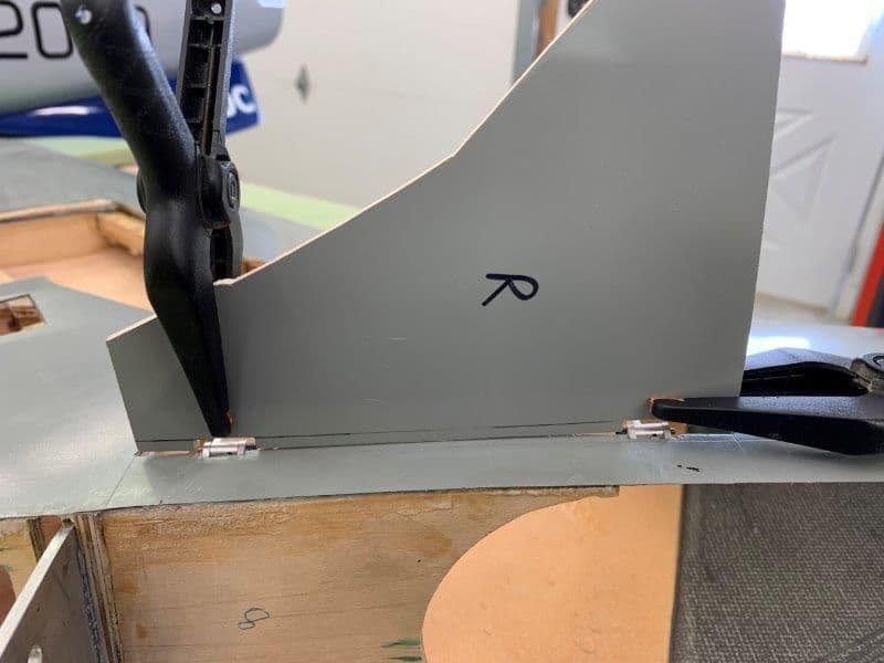
HInge install
After playing around with the hinges I did not trust the set screw to hold the hinge pins in so I drilled them out for a 2-56 screw
Other half drilled
2-56 screws in hinges
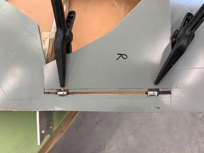
Hinges tacked in with Digipoxy MMA and held in place by hand for the 3 min set time, then tape in for 10 min cure
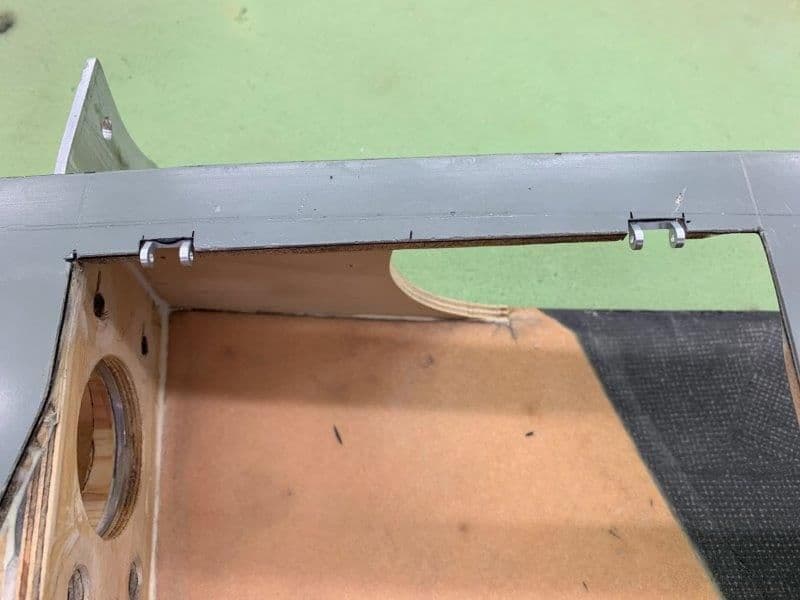
I use medium CA to reinforce the MMA. I will cover all glue joints with hysol after everything is working
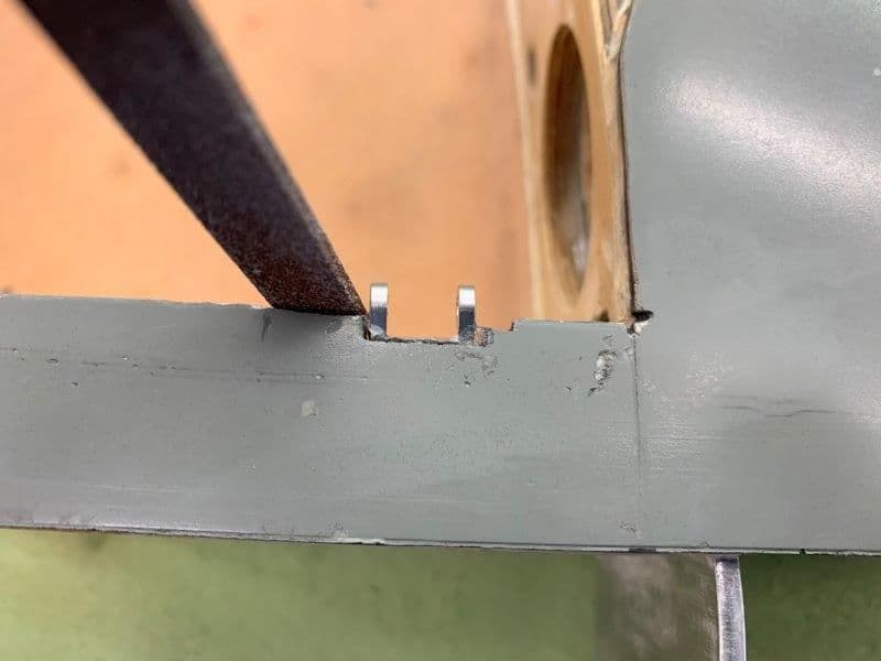
Material removed to give hinge bolt head clearance
2-56 screws were cut to proper length
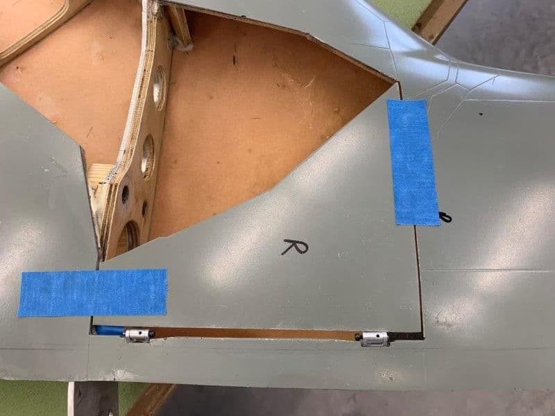
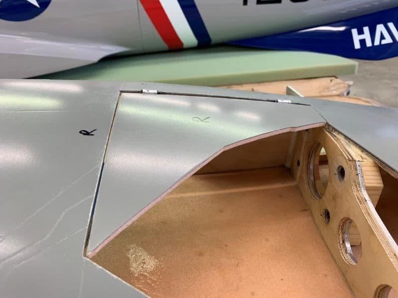
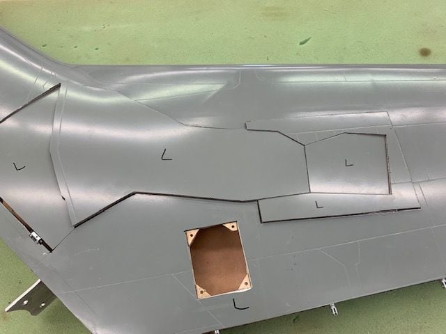
Door location dry fit
Door hinge relief cuts marked
Door hinge cut out done
After playing around with the hinges I did not trust the set screw to hold the hinge pins in so I drilled them out for a 2-56 screw
Other half drilled
2-56 screws in hinges
Hinges tacked in with Digipoxy MMA and held in place by hand for the 3 min set time, then tape in for 10 min cure
I use medium CA to reinforce the MMA. I will cover all glue joints with hysol after everything is working
Material removed to give hinge bolt head clearance
2-56 screws were cut to proper length
Door location dry fit
Door hinge relief cuts marked
Door hinge cut out done
 09-22-2019, 10:27 AM
#477
Thread Starter
My Feedback: (20)
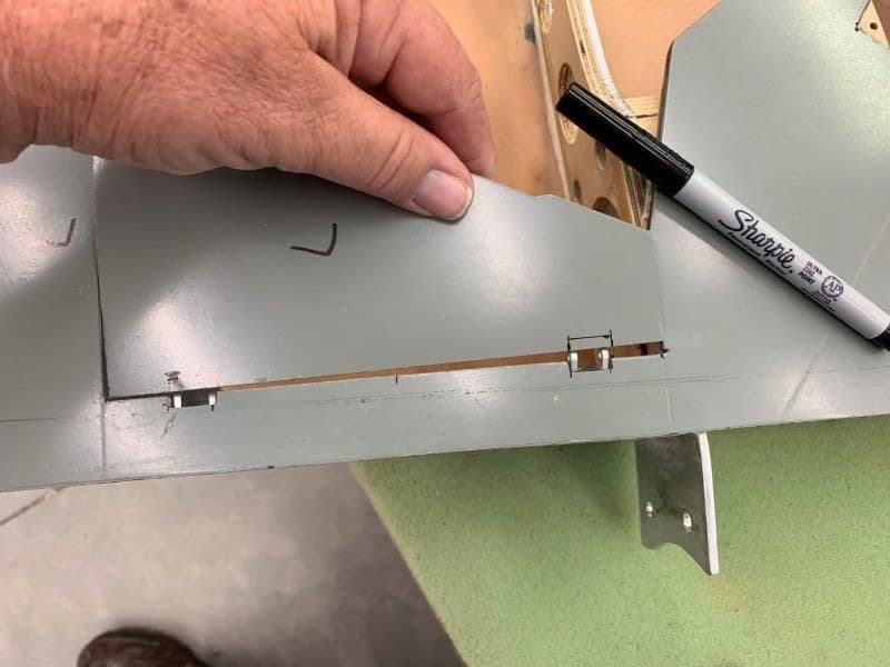
Mounting door to hinges
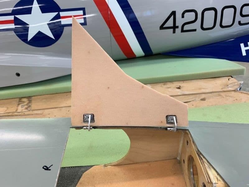
Door taped in place for dry fit
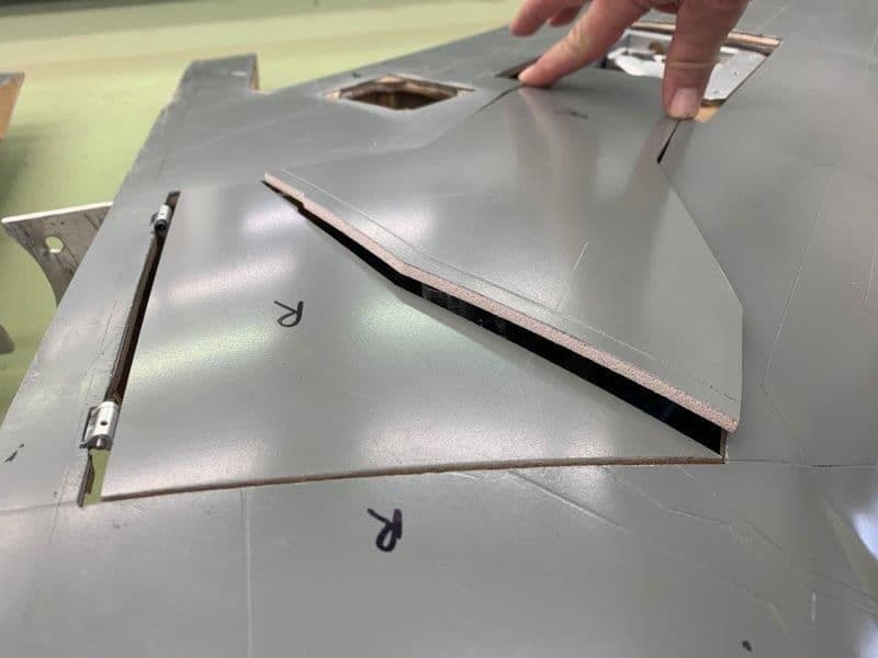
Door in open position contacts wing skin and binds when swinging open if clamped to hinges. Couldn't figure out how to make it work right.
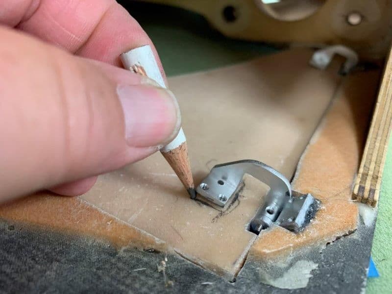
I marked hinge positions on back side of door with a short pencil
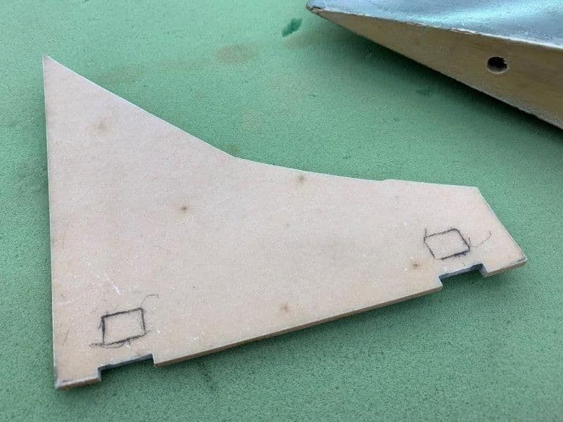
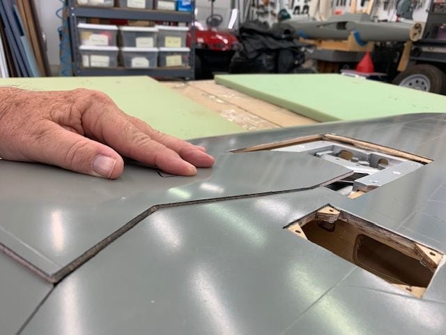
Door hinge position marked
Material removed down to outer skin to allow the door to sit flush with wing skin

Dry fit in closed position
Dry fit in open position had to have a gap to clear the curve. Here I spent about 4 hours trying to figure out how to make it work without a gap
I finally figured because of the curve of the wing surface I would have to trim the edge off the door and fill in the wing side to make it work. I couldn't just move the door away from he wing because then it would not fit the outer door on the strut.
So...I marked and cut off the edge of the door
Now the hinges were happy and worked but I have fill the gap. Another one I did not see coming.
Door taped in place for dry fit
Door in open position contacts wing skin and binds when swinging open if clamped to hinges. Couldn't figure out how to make it work right.
I marked hinge positions on back side of door with a short pencil
Door hinge position marked
Material removed down to outer skin to allow the door to sit flush with wing skin
Dry fit in closed position
Dry fit in open position had to have a gap to clear the curve. Here I spent about 4 hours trying to figure out how to make it work without a gap
I finally figured because of the curve of the wing surface I would have to trim the edge off the door and fill in the wing side to make it work. I couldn't just move the door away from he wing because then it would not fit the outer door on the strut.
So...I marked and cut off the edge of the door
Now the hinges were happy and worked but I have fill the gap. Another one I did not see coming.
09-22-2019, 10:49 AM
#478
Thread Starter
My Feedback: (20)
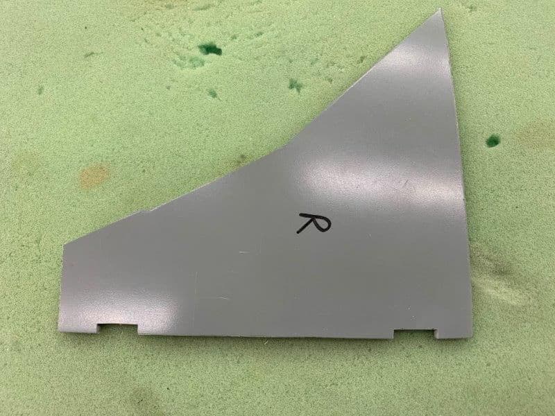
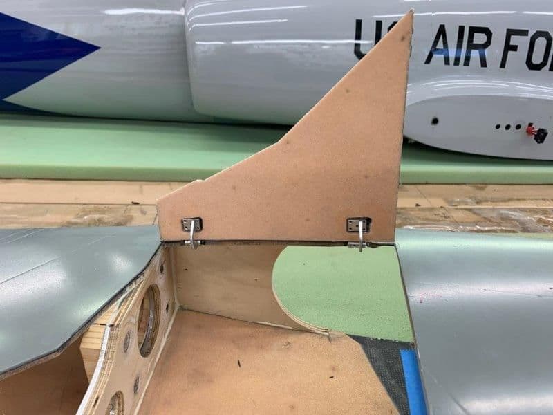
Doors attached to hinges and door horns
RIght side open after tack gluing to hinges with medium CA
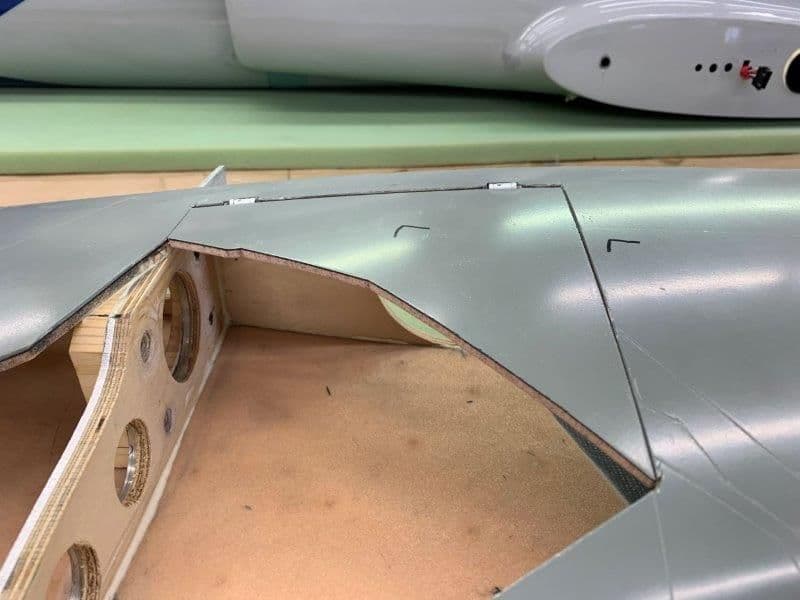
RIght side closed, flush with wing skin, and aligned with the lines for the main strut door
Same for the left side
Ditto on left side...
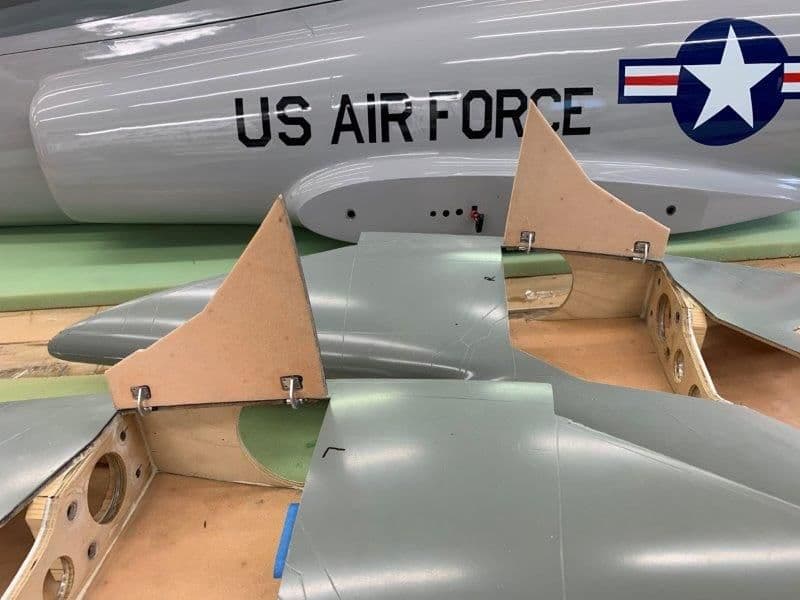
Both doors posing for photos. Getting the first one on the right took about 5 hours and 45 min on the left side, but it's done.
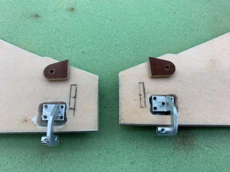
I found some old phenolic horns in the parts box left over from a Kangaroo kit I built about 20 years ago. I cut them off and they worked perfect for the gear door horns
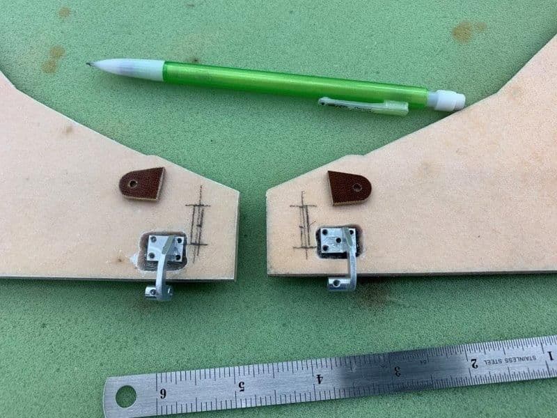
Center lines marked

Slots cut
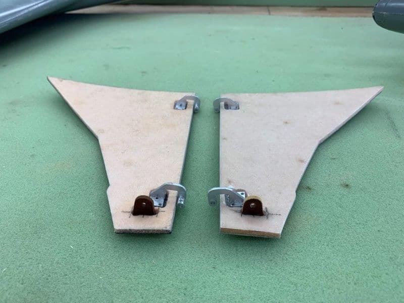
Horns glued in with medium CA. Holes are about 25mm from hinge line approximately equal to holes in servo arms
RIght side open after tack gluing to hinges with medium CA
RIght side closed, flush with wing skin, and aligned with the lines for the main strut door
Same for the left side
Ditto on left side...
Both doors posing for photos. Getting the first one on the right took about 5 hours and 45 min on the left side, but it's done.
I found some old phenolic horns in the parts box left over from a Kangaroo kit I built about 20 years ago. I cut them off and they worked perfect for the gear door horns
Center lines marked
Slots cut
Horns glued in with medium CA. Holes are about 25mm from hinge line approximately equal to holes in servo arms
Last edited by Viper1GJ; 09-22-2019 at 10:52 AM.
09-22-2019, 11:35 AM
#479
Thread Starter
My Feedback: (20)
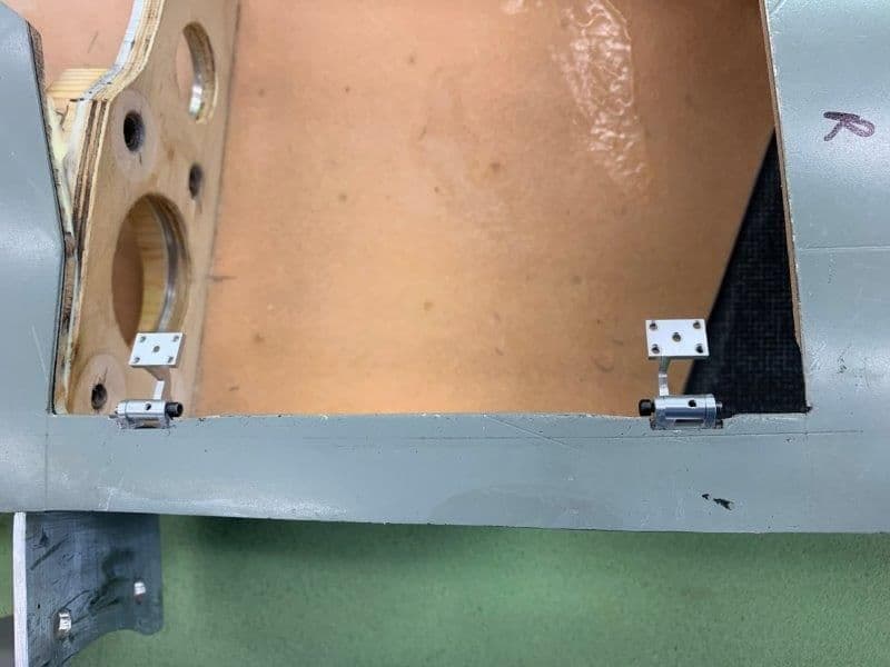
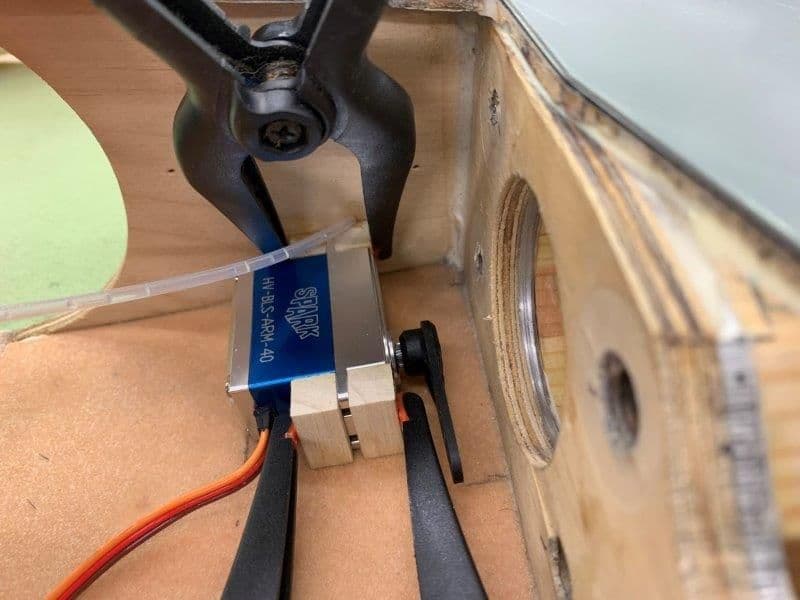
Installing inner gear door servos and linkage
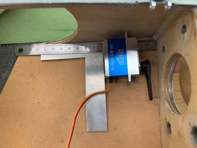
I needed about 12mm clearance from the servo arm to plywood wing spar for the 4-40 ball link. This translated to about 60 mm from the spar at the bottom of the servo.
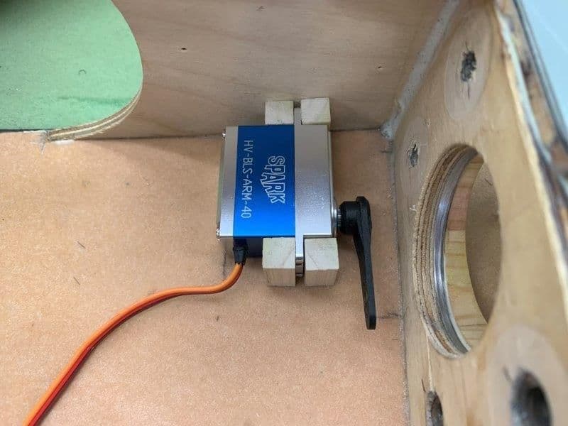
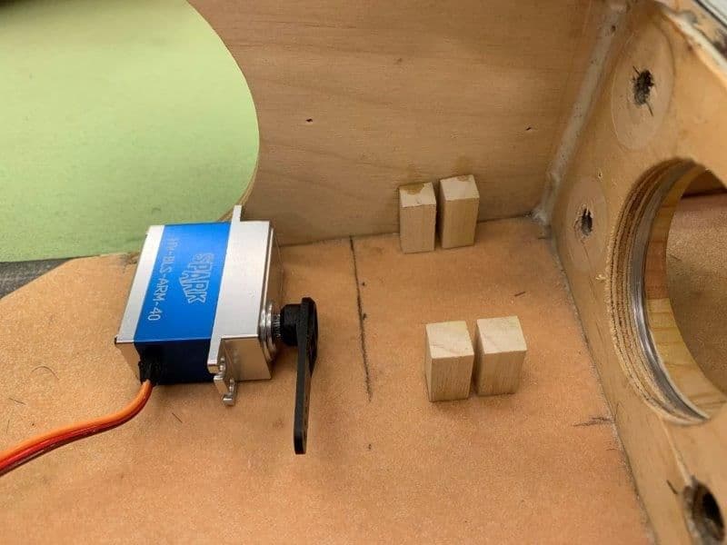
Servo mount dry fit. The servo needed to be as low as possible to clear the wheel. I decided to make a clamp style mount so I could access all screws from the wheel well. 3/8 x 3/8" poplar was used for the servo mounts.
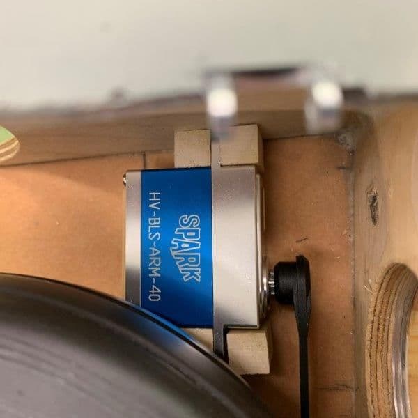
Clearance check with wheel in retracted positon
Clear of wheel
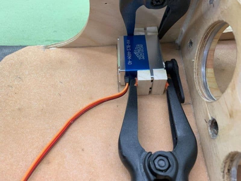
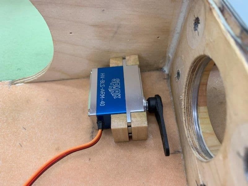
Wood mounts clamped to servo and servo in position on line
Mounts tack glued in with thin CA.
Servo removed for saturation gluing with thin CA
Tops of wood mounts saturated with thin CA to harden the wood for the servo screw threads. I go around all the joints with hysol after everything is installed and working.
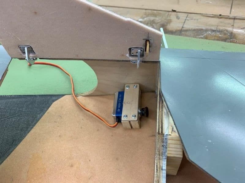
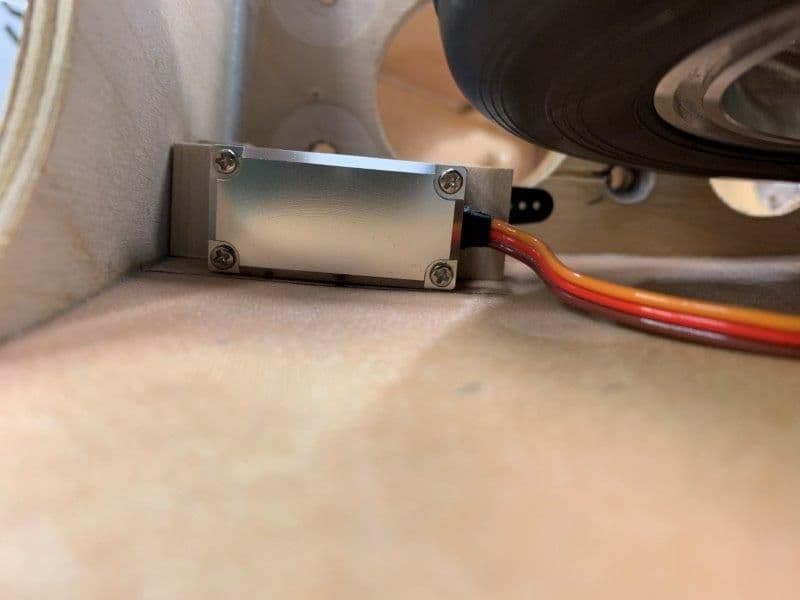
Plywood clamp screwed into positon. Now servo is easily removed through the wheel well opening

4-40 ball links and threaded rods attached and adjusted for proper movement.
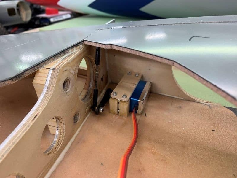
I was able to use the two 50mm 4-40 threaded rods I had cut for the nose gear doors but could not use. Rather be lucky than good any day!
I needed about 12mm clearance from the servo arm to plywood wing spar for the 4-40 ball link. This translated to about 60 mm from the spar at the bottom of the servo.
Servo mount dry fit. The servo needed to be as low as possible to clear the wheel. I decided to make a clamp style mount so I could access all screws from the wheel well. 3/8 x 3/8" poplar was used for the servo mounts.
Clearance check with wheel in retracted positon
Clear of wheel
Wood mounts clamped to servo and servo in position on line
Mounts tack glued in with thin CA.
Servo removed for saturation gluing with thin CA
Tops of wood mounts saturated with thin CA to harden the wood for the servo screw threads. I go around all the joints with hysol after everything is installed and working.
Plywood clamp screwed into positon. Now servo is easily removed through the wheel well opening
4-40 ball links and threaded rods attached and adjusted for proper movement.
I was able to use the two 50mm 4-40 threaded rods I had cut for the nose gear doors but could not use. Rather be lucky than good any day!
Last edited by Viper1GJ; 09-22-2019 at 11:38 AM.
 09-23-2019, 05:29 PM
#481
Thread Starter
My Feedback: (20)
Rav, I got it from Danny at Aeropanda.com.
Digipoxy 5Min MMA is very different than Hysol. It mixes very easy and is very sticky almost stringing when you pull the mixing stick away. So it sticks to the surface you apply it to very well and easy to spread. But is harder to get a smooth surface. It does not self level like Hysol. I guess because it sets up in about 3-4 min. It is firm in about 10 min and cured in 30 min. It has a smell also. So you have to have the parts ready since there is very little working time. I like to use it for things that can be done fast and easy or to tack parts on that may not have a good mating surface and glue later with CA or Hysol. It worked great on the hinges since they were off a little in contacting the gluing surface and there was a gap to fill. The MMA filled the small gaps and cured with the hinges in the correct spot.
Hysol has a much longer working time and it is easier to get a smooth surface on the glue since it somewhat self levels. Also it is much easier to get Hysol off areas that you don't want it on. I use lots of Qtips to clean up the hysol joints if necessary. That is really not possible with the MMA
Anybody else have experience with it feel free to chime in. I don't know much about the tech specs but it sure is handy.
Gary
Last edited by Viper1GJ; 09-23-2019 at 05:39 PM.
09-23-2019, 06:02 PM
#482
Thread Starter
My Feedback: (20)
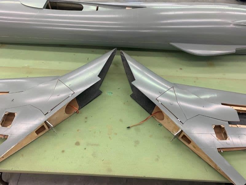
Main landing gear middle and outer doors
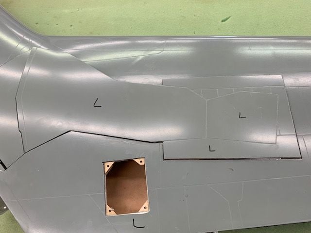
The gear doors before cutting middle door from outside door
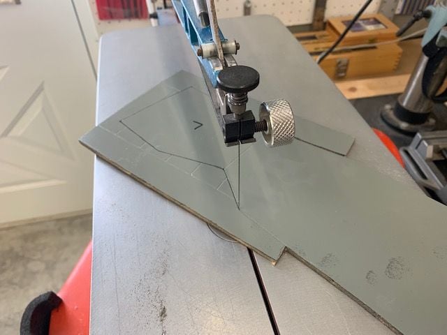
Doors cut apart on scroll saw. Used a couple of blades cutting through the glass and carbon fiber layers
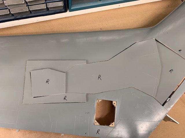
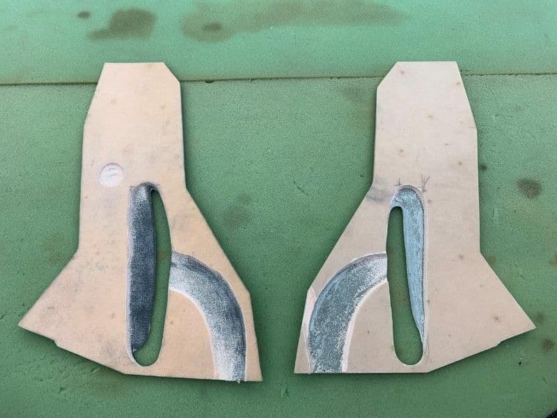
Right side done
Left side done
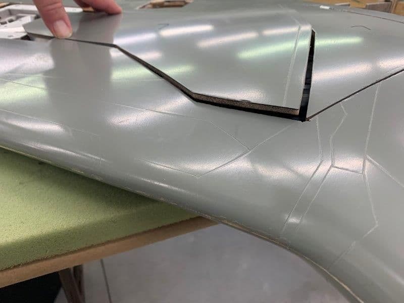
Looking and pondering how to do the doors. Looks like they may actually fit flush with some of the foam backing removed in the right places
If material removed on back of door it should fit flush here also
Ditto
Trying to figure a way to attach door so it is removeable and not drilling into the strut. Thinking about making two sheet metal brackets that would clamp the door to the strut with bolts and nuts. The brackets have to leave room for the chute RPM sensor and magnets also.
The door has to rotate with the lower strut when it is retracted and extended. It also has to be mounted on the strut so it is flush with the surface when retracted. So I will have to figure out hot to set the proper gap which is not the same on either edge or end. Not sure how now, but thinking waxing the strut and then making a bed of epoxy putty and pressing the door on to the strut till it is flush and let it cure. Then remove the door from the strut and clean up the squeeze out to make a custom door mount for each side. Any ideas or suggestions appreciated.

What is clear is that each door will have to be custom fit. No fast way to do it.
This will wrap up work this week. Spent most of the day packing the camper to go to Super Jets South in Georgia. Leaving tomorrow and back next week hopefully.
Gary
The gear doors before cutting middle door from outside door
Doors cut apart on scroll saw. Used a couple of blades cutting through the glass and carbon fiber layers
Right side done
Left side done
Looking and pondering how to do the doors. Looks like they may actually fit flush with some of the foam backing removed in the right places
If material removed on back of door it should fit flush here also
Ditto
Trying to figure a way to attach door so it is removeable and not drilling into the strut. Thinking about making two sheet metal brackets that would clamp the door to the strut with bolts and nuts. The brackets have to leave room for the chute RPM sensor and magnets also.
The door has to rotate with the lower strut when it is retracted and extended. It also has to be mounted on the strut so it is flush with the surface when retracted. So I will have to figure out hot to set the proper gap which is not the same on either edge or end. Not sure how now, but thinking waxing the strut and then making a bed of epoxy putty and pressing the door on to the strut till it is flush and let it cure. Then remove the door from the strut and clean up the squeeze out to make a custom door mount for each side. Any ideas or suggestions appreciated.
What is clear is that each door will have to be custom fit. No fast way to do it.
This will wrap up work this week. Spent most of the day packing the camper to go to Super Jets South in Georgia. Leaving tomorrow and back next week hopefully.
Gary
 09-25-2019, 06:04 PM
#485
Thread Starter
My Feedback: (20)
Hi Paul,
I spoke to Dave to day at SJS in Georgia about just that. I think I will make a wood mock up and some measurements and send it to him and he will be able to make some 3D printed brackets.
Love your thread and progress in the Bucc.
Thanks,
Gary
I spoke to Dave to day at SJS in Georgia about just that. I think I will make a wood mock up and some measurements and send it to him and he will be able to make some 3D printed brackets.
Love your thread and progress in the Bucc.
Thanks,
Gary
09-26-2019, 05:51 PM
#486
Thread Starter
My Feedback: (20)
Congratulations to Bob Rullie for a successful flight on his F-105!
Shortly after I arrived at SJS 2019 in Georgia I got an email from Bob Rullie who I mentioned in post #1 and #2. Bob took 4 years to build his plane and flew a successful flight on his F-105 in 2017 but it was quite tail heavy. After a two year delay and some turbine issues he got in a good flight last week in NY. I corresponded with him by email and he said it flew well and he was planning on flying again but he found a small crack in fuse where the air intake connects to the fuse and wanted to investigate before flying again.
Here is a video link of his flight:
Congrats Bob!
09-30-2019, 05:57 PM
#487
Thread Starter
My Feedback: (20)
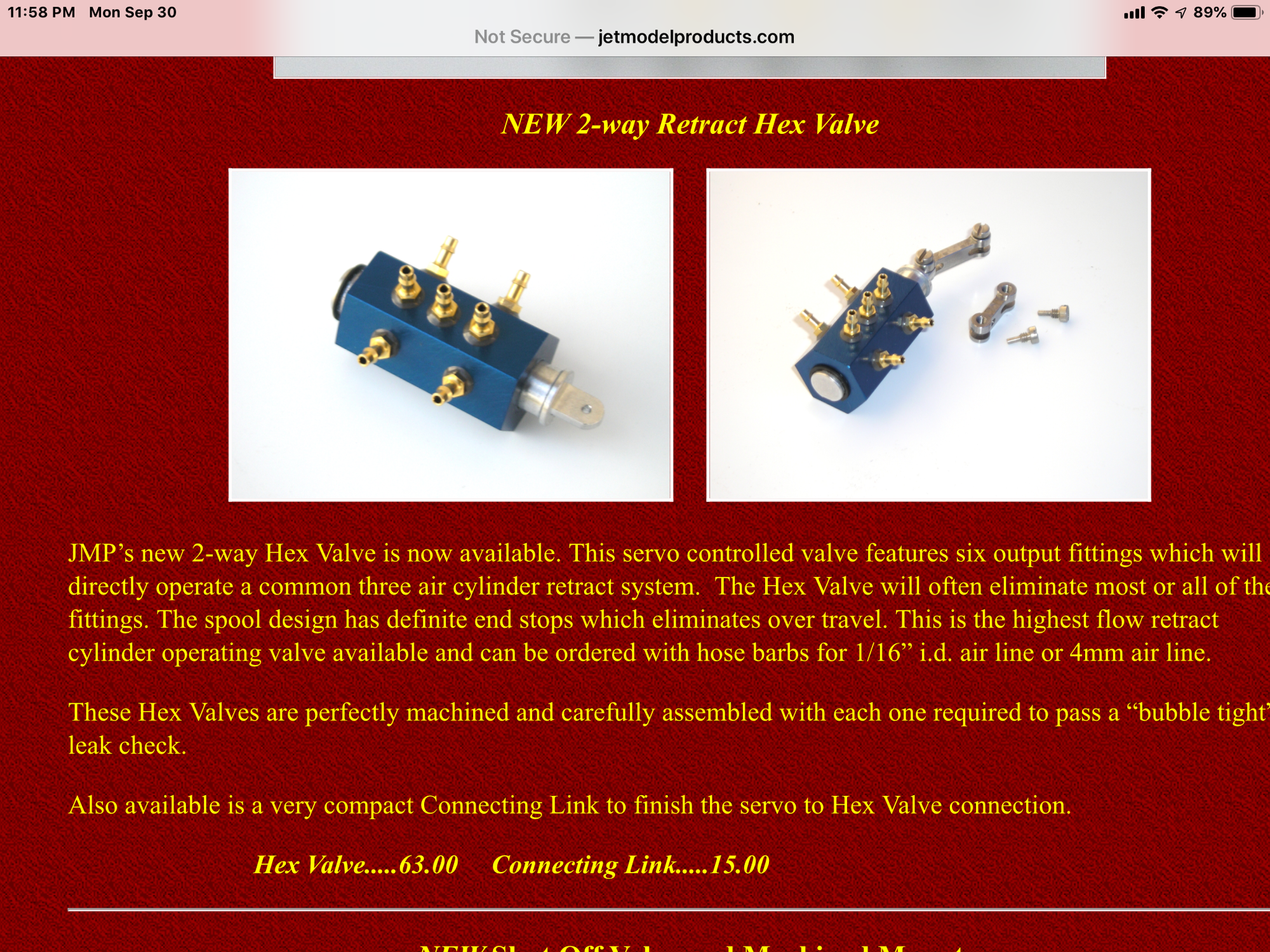
I want to test the main landing gear retract power on air to see if the two cylinders on each gear can lift the long struts and big wheels.
Can you guys advise me on the best high flow retract valves to use so I don't get stuck with not enough air to move the struts up. Electric or mechanical?
Should I plan one valve for each gear?
I have not ever tried to move gear this big and heavy gear on air before so I'm looking for advice before I buy a bunch of useless hardware. I am also thinking about hydraulics if air will not hack it.
Thanks,
Gary
Last edited by Viper1GJ; 09-30-2019 at 06:00 PM.

 12-05-2019, 05:55 AM
#490

Congratulations to Bob Rullie for a successful flight on his F-105!
Shortly after I arrived at SJS 2019 in Georgia I got an email from Bob Rullie who I mentioned in post #1 and #2. Bob took 4 years to build his plane and flew a successful flight on his F-105 in 2017 but it was quite tail heavy. After a two year delay and some turbine issues he got in a good flight last week in NY. I corresponded with him by email and he said it flew well and he was planning on flying again but he found a small crack in fuse where the air intake connects to the fuse and wanted to investigate before flying again.
Here is a video link of his flight:
https://www.youtube.com/watch?v=fIseF7d_Js4&app=desktop
Congrats Bob!
 12-05-2019, 01:41 PM
#491
Thread Starter
My Feedback: (20)
Gary
01-23-2020, 06:33 PM
#492
Thread Starter
My Feedback: (20)
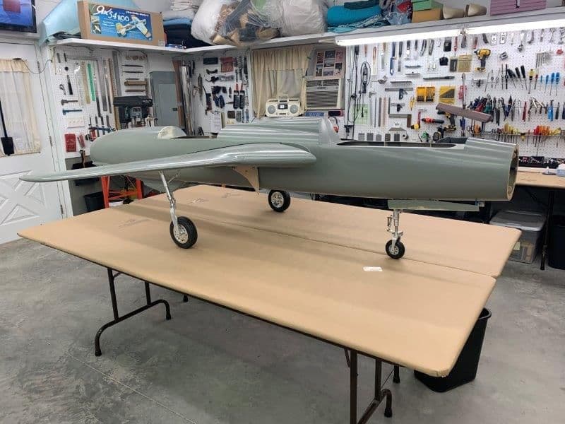
I finally got back to work on the F-105 today after a long break since last SEP. During that time I completed turbine conversions on my Freewing F-22 and F-4 EDF foamy models. Both now have K-45G3 turbines installed. The F-22 flies great and is much more fun than with EDF. It has been too cold to fly the F-4 since I completed it last week so I'm hoping it will be the same. We will see.
I finally got the work tables cleaned off and shop reorganized after the Christmas and New Years break after multiple grandkids played in the shop. The task I was working on last SEP when I stopped was main gear doors. It didn't take long to determine the fit of the main gear doors was not going to be easy. What's new with this model. However the work break has allowed me to approach the project with a "just get it done approach" and I'm not going to worry much about how It will look or what I have to do to get it done. I just want it done. So here we go...
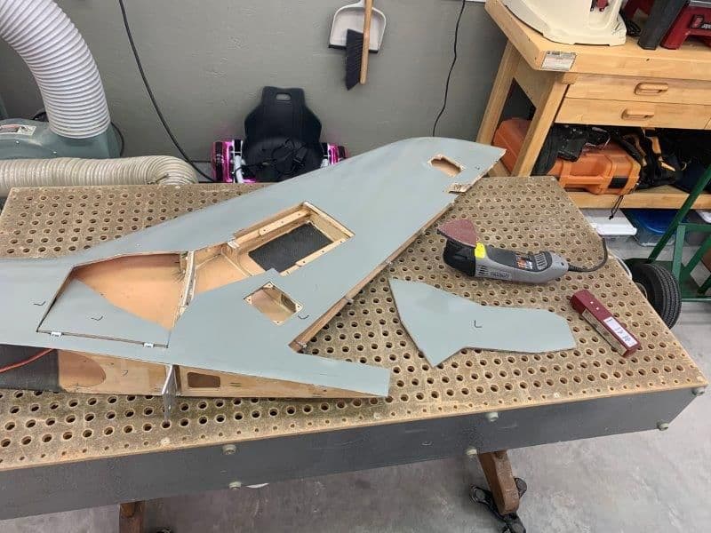
The first task was to trim the doors to fit into the gear well opening. I did this on the down draft sanding table to catch the carbon fiber dust.
The aluminum spars were too high and had to be cut down to allow the door to fit over them.
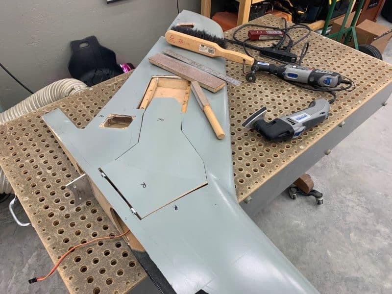
Several tools were used to shape the edges of the doors to fit the gear well opening. After about an hour I got both doors to fit ok with some clearance around the edges.
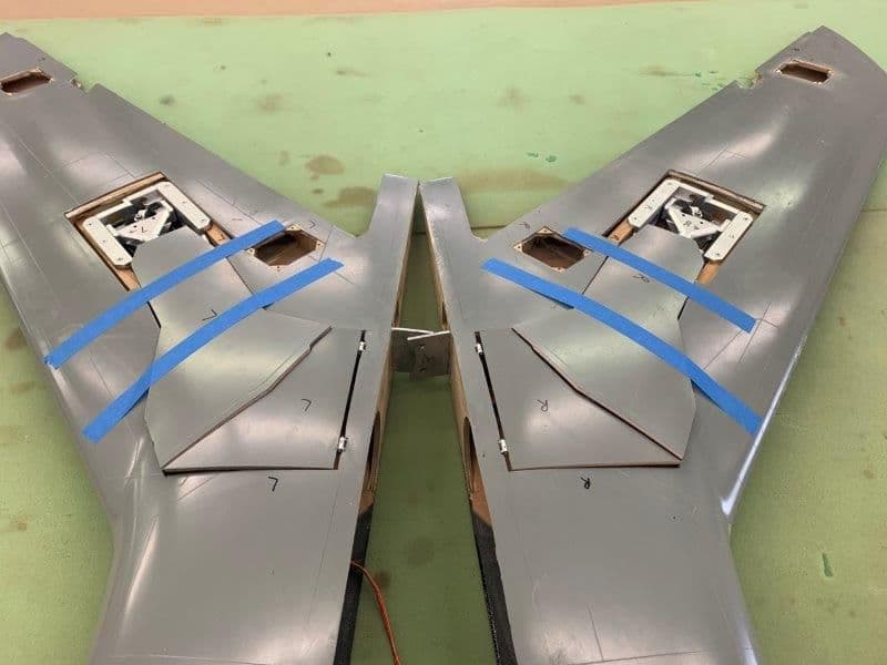
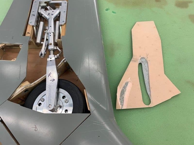
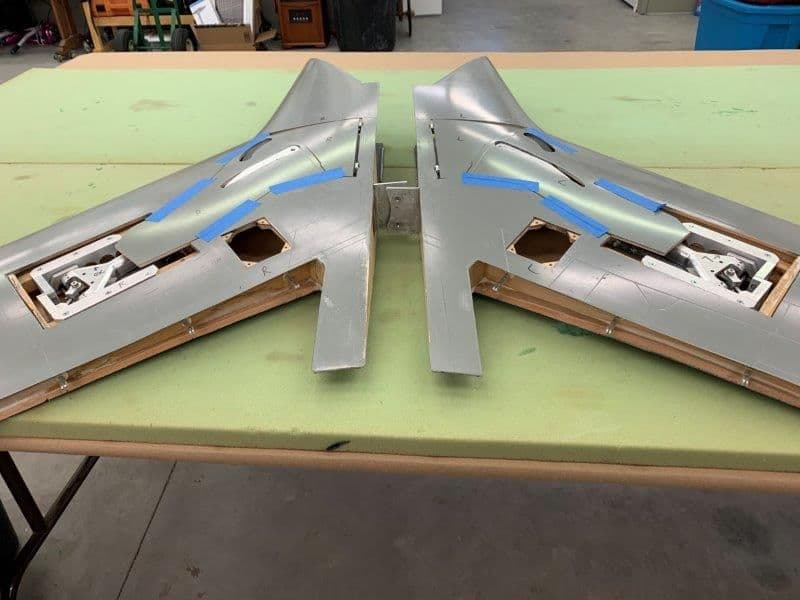
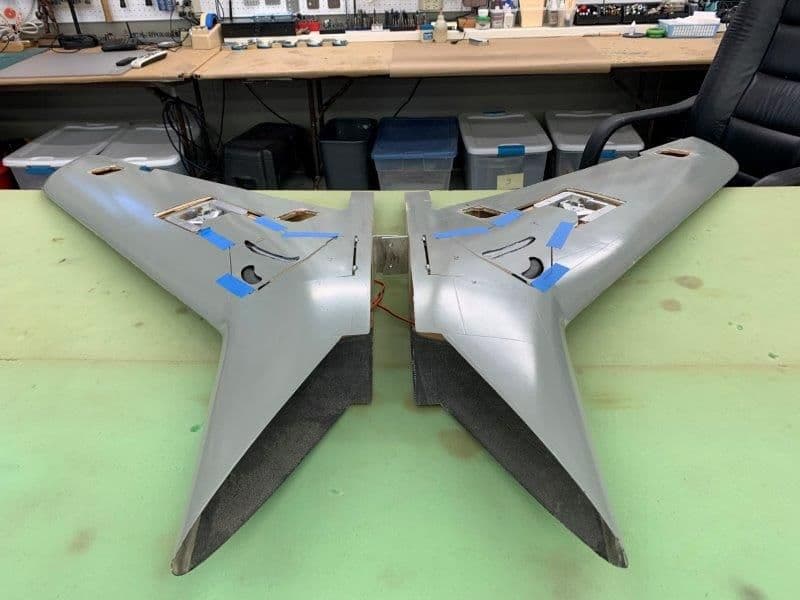
After door fitting I installed the main gears in each wing to check the fit on the gear struts. This photo was before I installed the gear.
I knew it would be bad, but I did not expect this much gap. The problem is when the proper tow angle is set on the wheel when the gear is extended, it rotates when retracted and does not lay flat in the gear well. This causes the dear door not to fit flush with the wing skin. If the outer end of the door is held flush with the wing skin, the inside edge sticks out about 5-6mm over the wing skin because the gear strut sticks out too far.
It's worse on the right side. After thinking how to fix it, I decided I would have to carve out the bottom of the gear door and even cut through the outer skin to get them to fit flush with the wing skin. In the worst area the strut will stick out of the door skin slightly. I will have to lay glass over the strut and then build up a slight mound on the doors to hide the strut. I can then feather it to the door edges with Icing putty and it wont look too bad. At this point its the best I can do.
So the next task was to set both main gear struts tow angle so the tires are parallel to the fuse centerline. This required mounting the wings and then setting the proper tow angle for each strut. Then I can mark the set screw positions on the strut pin and grind flat spots on the pin to keep the strut from rotating on the pin. Once I get the proper tow angle set I can then go back and figure out how to mount the gear doors.
I finally got the work tables cleaned off and shop reorganized after the Christmas and New Years break after multiple grandkids played in the shop. The task I was working on last SEP when I stopped was main gear doors. It didn't take long to determine the fit of the main gear doors was not going to be easy. What's new with this model. However the work break has allowed me to approach the project with a "just get it done approach" and I'm not going to worry much about how It will look or what I have to do to get it done. I just want it done. So here we go...
The first task was to trim the doors to fit into the gear well opening. I did this on the down draft sanding table to catch the carbon fiber dust.
The aluminum spars were too high and had to be cut down to allow the door to fit over them.
Several tools were used to shape the edges of the doors to fit the gear well opening. After about an hour I got both doors to fit ok with some clearance around the edges.
After door fitting I installed the main gears in each wing to check the fit on the gear struts. This photo was before I installed the gear.
I knew it would be bad, but I did not expect this much gap. The problem is when the proper tow angle is set on the wheel when the gear is extended, it rotates when retracted and does not lay flat in the gear well. This causes the dear door not to fit flush with the wing skin. If the outer end of the door is held flush with the wing skin, the inside edge sticks out about 5-6mm over the wing skin because the gear strut sticks out too far.
It's worse on the right side. After thinking how to fix it, I decided I would have to carve out the bottom of the gear door and even cut through the outer skin to get them to fit flush with the wing skin. In the worst area the strut will stick out of the door skin slightly. I will have to lay glass over the strut and then build up a slight mound on the doors to hide the strut. I can then feather it to the door edges with Icing putty and it wont look too bad. At this point its the best I can do.
So the next task was to set both main gear struts tow angle so the tires are parallel to the fuse centerline. This required mounting the wings and then setting the proper tow angle for each strut. Then I can mark the set screw positions on the strut pin and grind flat spots on the pin to keep the strut from rotating on the pin. Once I get the proper tow angle set I can then go back and figure out how to mount the gear doors.
01-25-2020, 06:59 PM
#493
Thread Starter
My Feedback: (20)
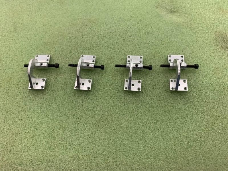
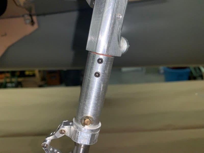
The mod I had Mitch at Down and Locked make was replaced 2 roll pins through the MLG strut pin for 4 set screws.
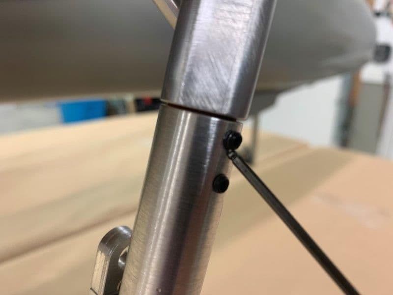
This mod allows me to set the tow angle of each MLG strut by loosening the set screws and rotating the lower strut.
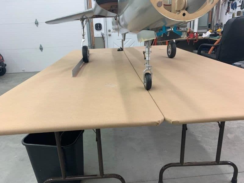
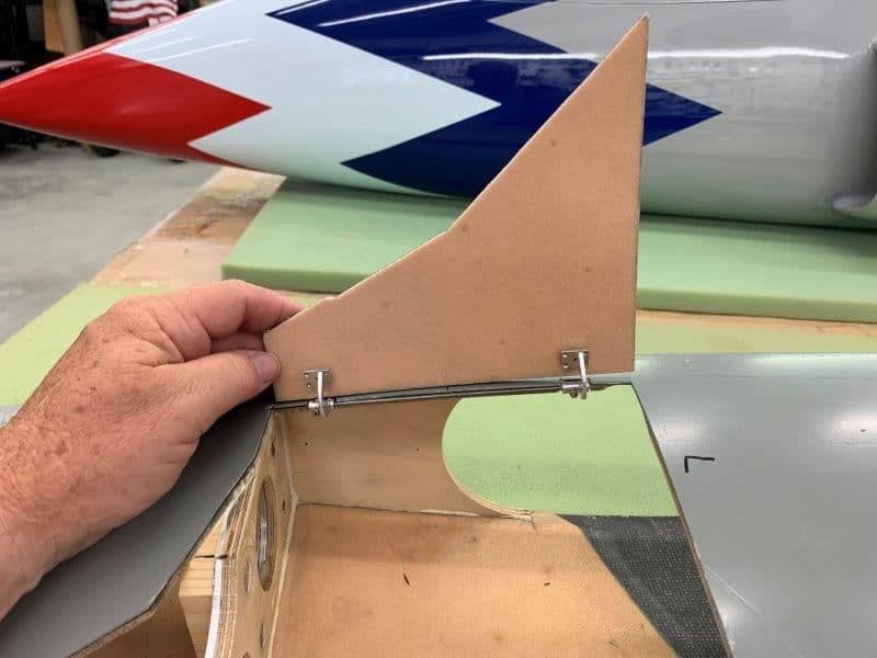
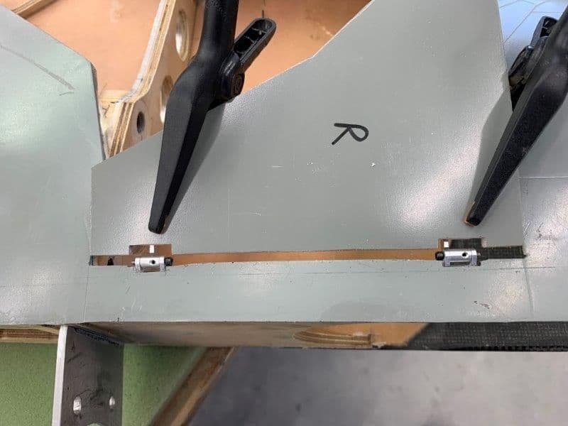
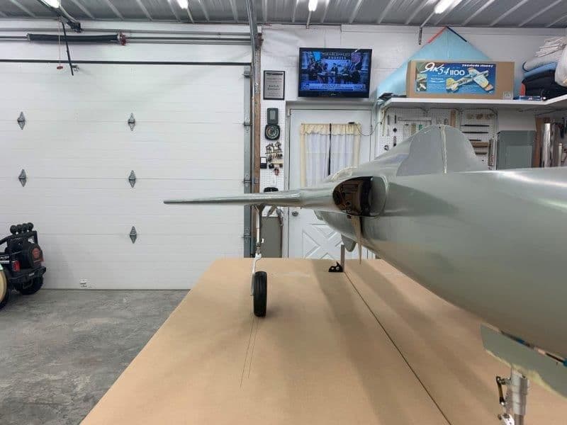
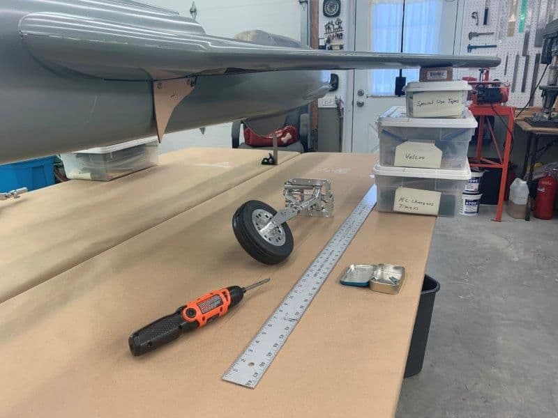
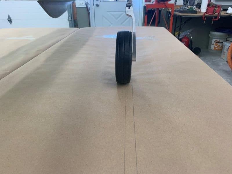
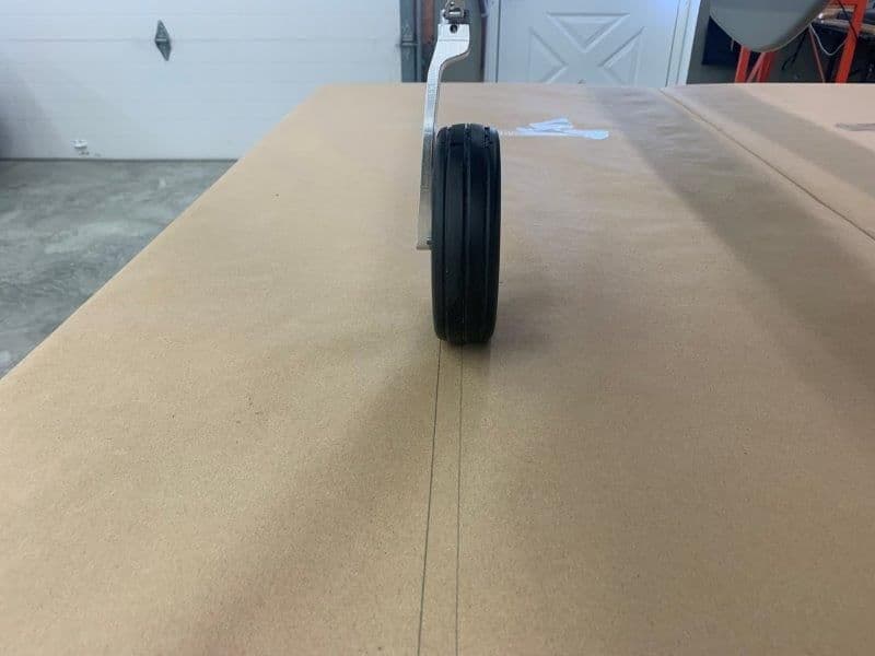
The jet was set on the table and the tail fin aligned with a square. Then parallel lines were drawn on the table under each tire.
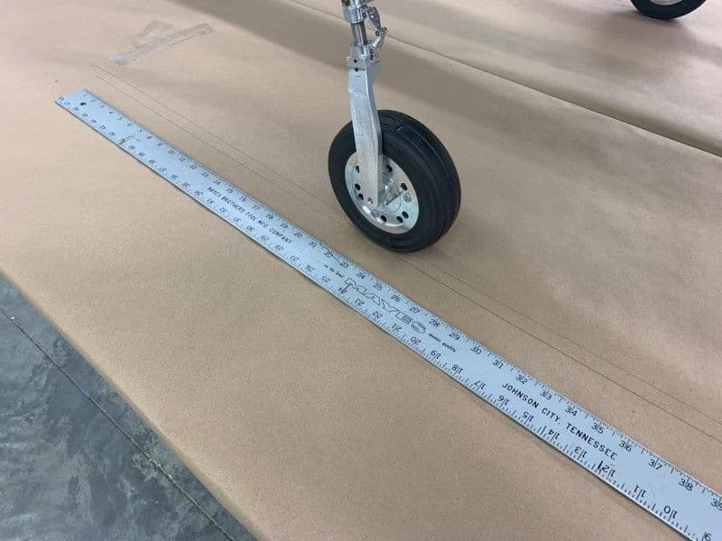
The proper alignment was set on each strut by using the aluminum straight edge against the tire.
Right side done
Left side done.
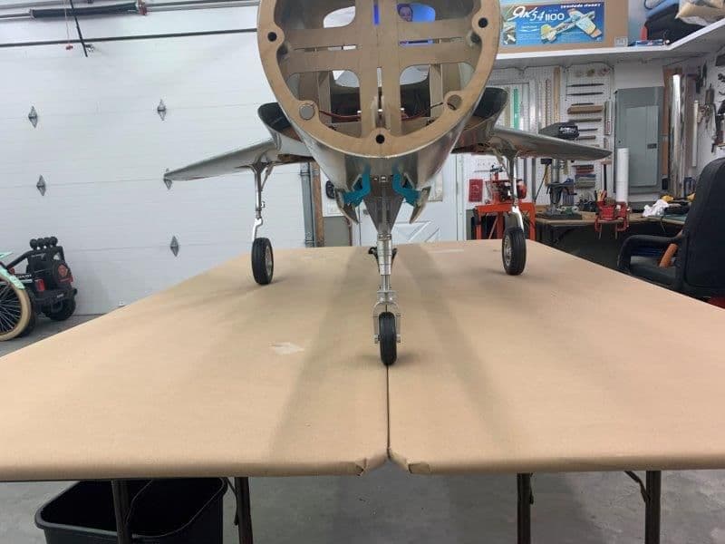
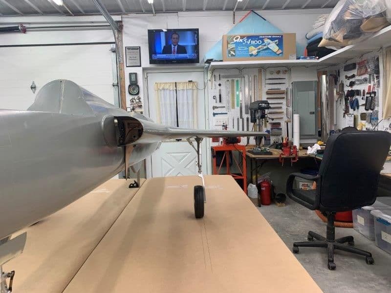
View from the front
All set screws tightened after double checking the alignment.
This mod allows me to set the tow angle of each MLG strut by loosening the set screws and rotating the lower strut.
The jet was set on the table and the tail fin aligned with a square. Then parallel lines were drawn on the table under each tire.
The proper alignment was set on each strut by using the aluminum straight edge against the tire.
Right side done
Left side done.
View from the front
All set screws tightened after double checking the alignment.
01-25-2020, 07:09 PM
#494
Thread Starter
My Feedback: (20)
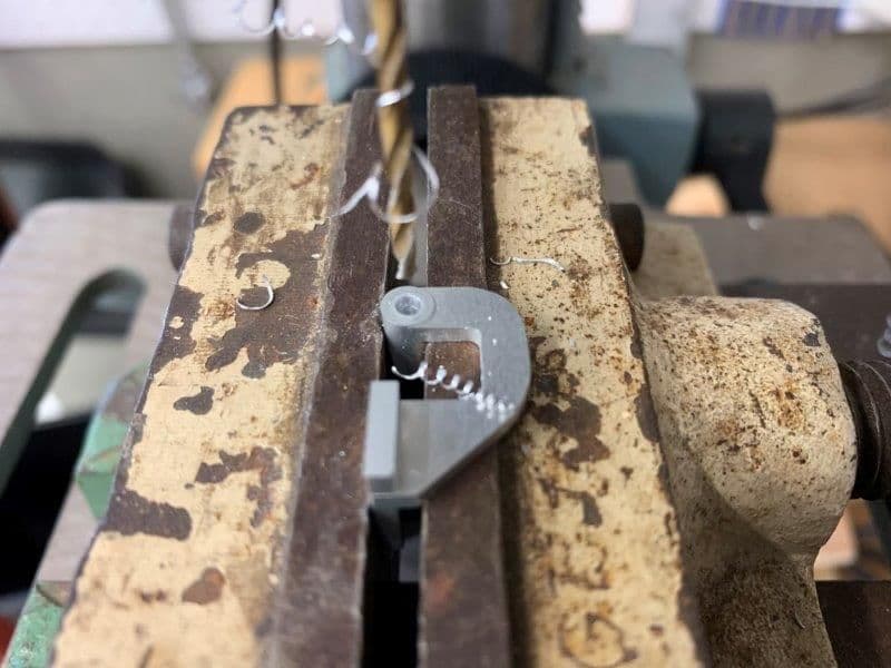
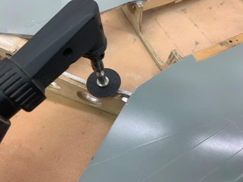
Next steps were to grind flats under the set screws so the lower strut will not twist under stress.
Jet jacked up with plastic boxes and MLG removed

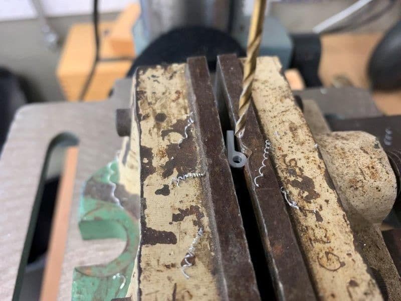
One set screw at a time was removed and a small rotary tool bit use to mark the set screw position on the strut pin

Tool marks on the pin
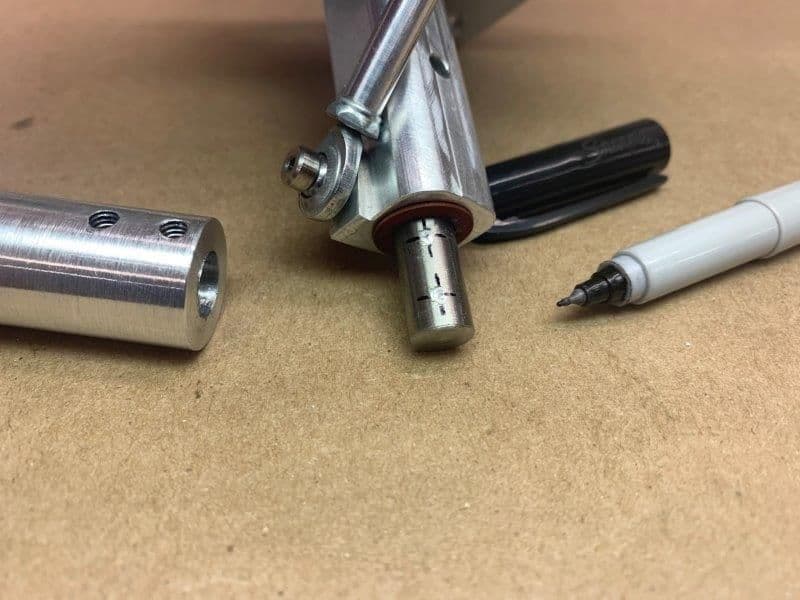
Center lines marked with a Sharpie pen to keep center located when using grinding wheel.
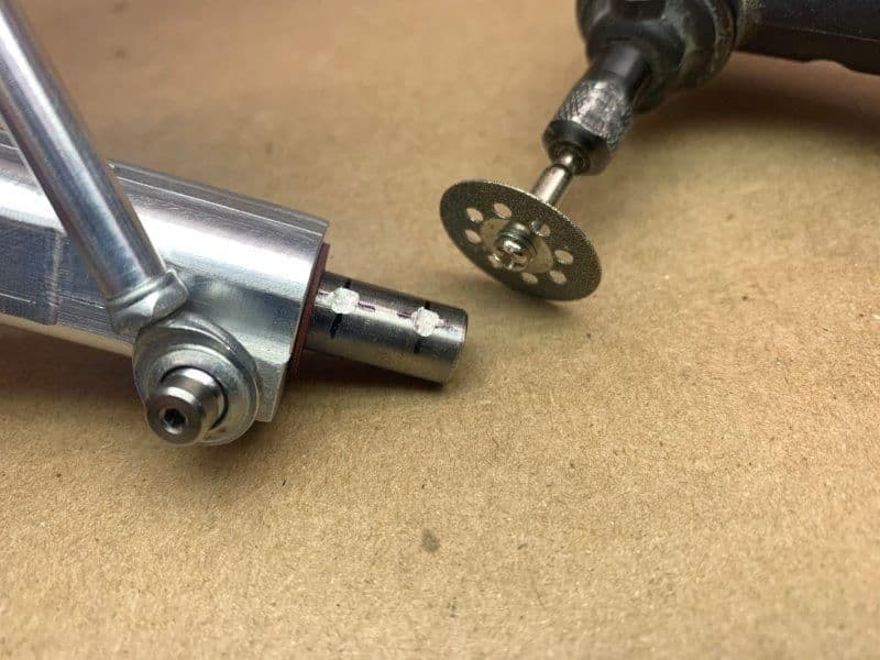
A diamond rotary disc was used to grind flats on the titanium pins. All set screws replaced and MLG re-installed into the wing.
Alignment rechecked on left side
Checked on right side
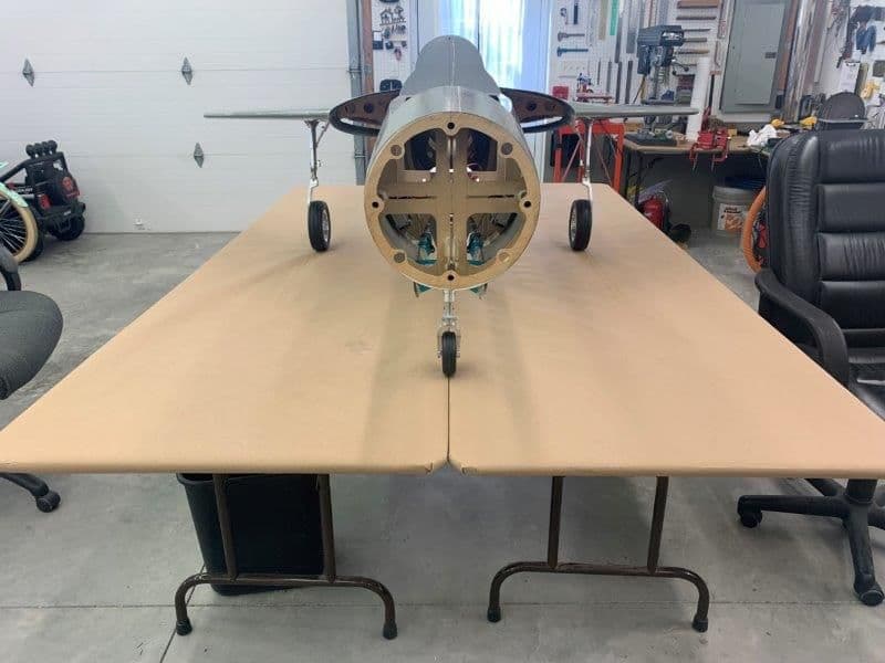
Done!
Jet jacked up with plastic boxes and MLG removed
One set screw at a time was removed and a small rotary tool bit use to mark the set screw position on the strut pin
Tool marks on the pin
Center lines marked with a Sharpie pen to keep center located when using grinding wheel.
A diamond rotary disc was used to grind flats on the titanium pins. All set screws replaced and MLG re-installed into the wing.
Alignment rechecked on left side
Checked on right side
Done!
Last edited by Viper1GJ; 01-25-2020 at 07:12 PM.
 01-25-2020, 07:33 PM
#496
Thread Starter
My Feedback: (20)
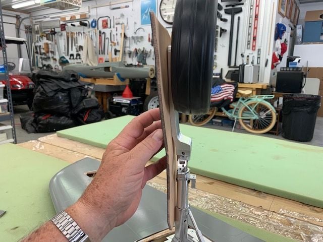
The problem with the gear is that it is not designed to correctly rotate when retracting or extending. If you set the proper ground alignment, the alignment is incorrect inside the wheel well. The strut and tire stick through the gear door if the gear door is flush with the wing skin. Since I have no ability to redesign and and fabricate new gear parts, I elected to fix the problem by cutting the gear doors to fit. This will require a small bump on the outside of the gear doors when finished but it is not as bad as I thought it would be at first. So in the spirit of "Git er done"...let the grinding begin...

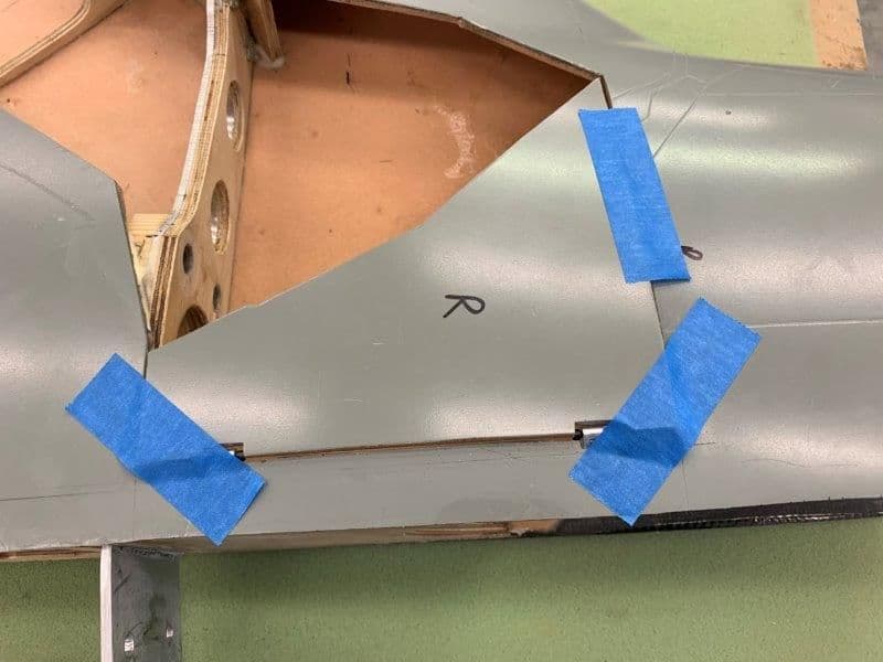
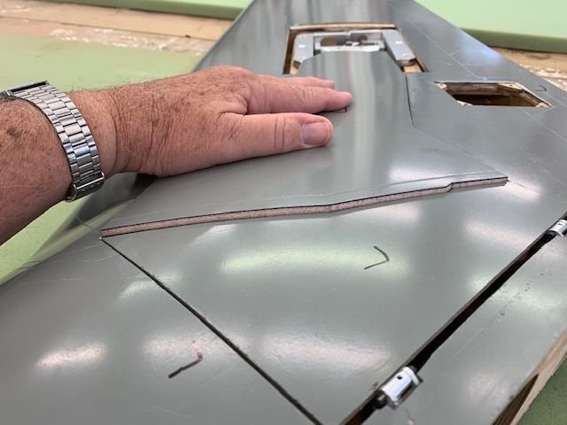
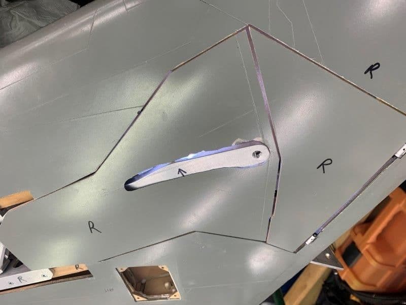
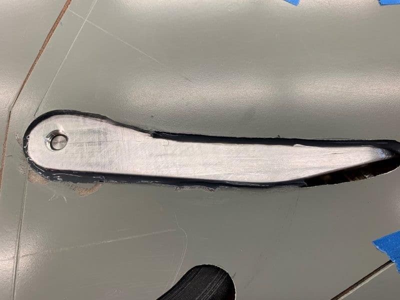
First step was to remove the wheels to fit the gear doors to each strut and flush with the wing skin
Doors taped in place for marking strut locations
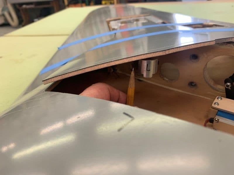
A sort pencil used to mark the position of the struts on the inside of the doors

Doors marked
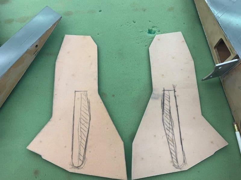
First guess of where to start removing material. As it turned out I had to cut it all out.
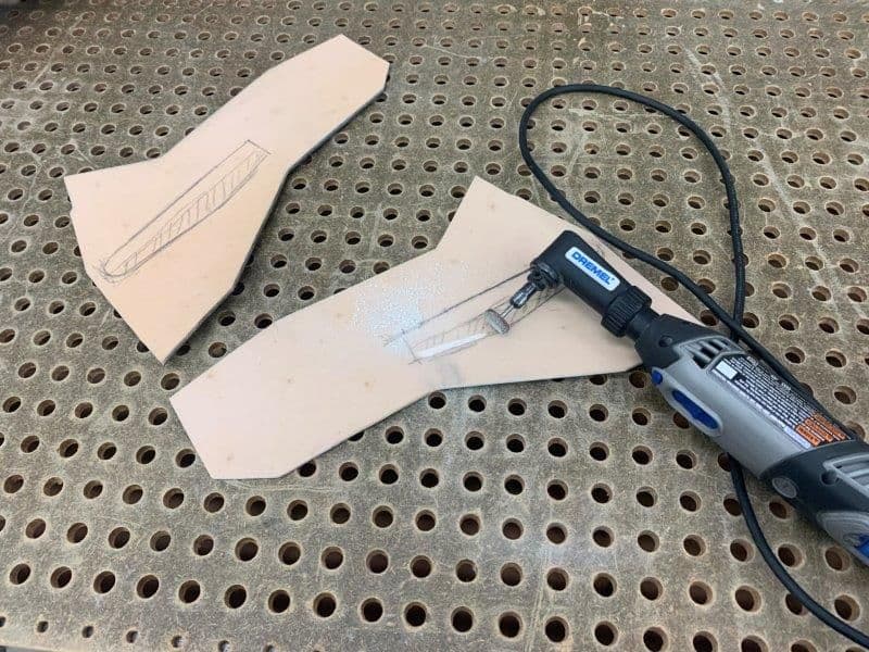
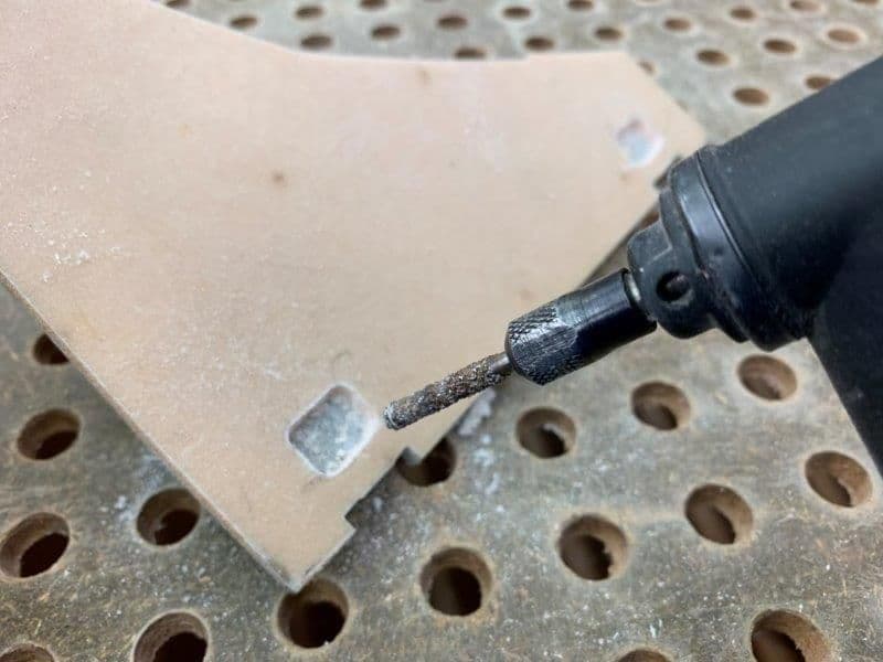
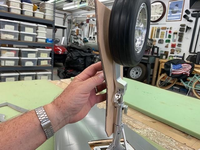
Perma grit wheel used to remove material on inside of gear doors
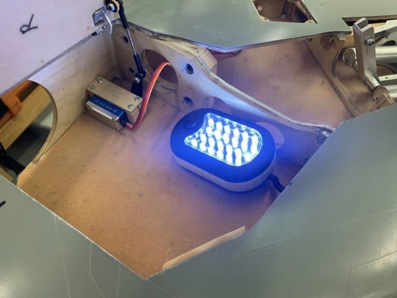
An led light inside the gear well help see where the strut was touching the door keeping it up from the wing skin
Final cut on the right side strut
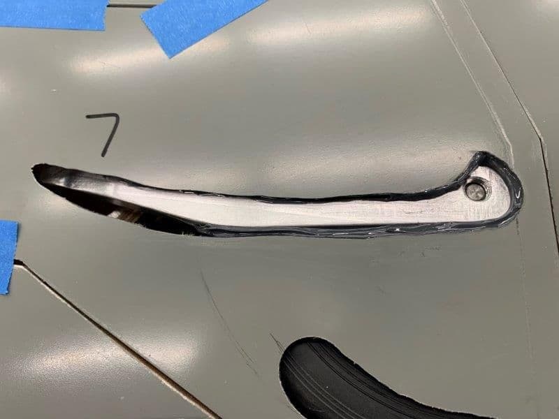
Next issue was tire clearance from the doors. Initial cuts here, but eventually had to cut a whole in each side.
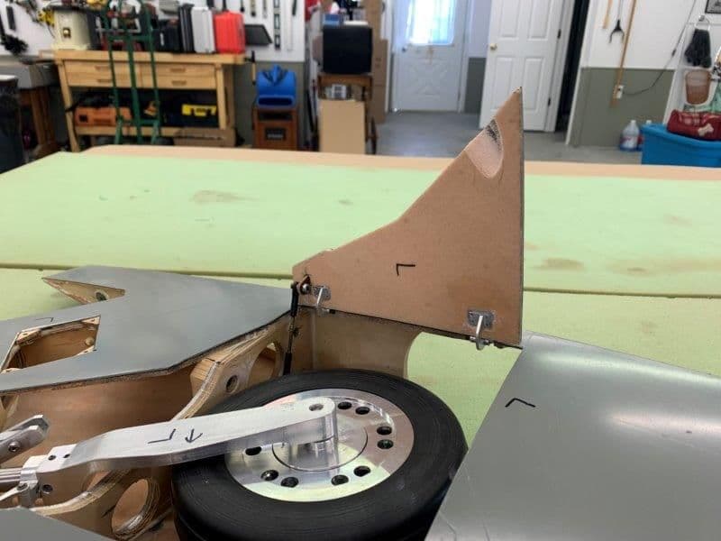
Tire relief cut in inner doors
Almost done but I eventually had to cut through the door skin to get tire clearance.
First step was to remove the wheels to fit the gear doors to each strut and flush with the wing skin
Doors taped in place for marking strut locations
A sort pencil used to mark the position of the struts on the inside of the doors
Doors marked
First guess of where to start removing material. As it turned out I had to cut it all out.
Perma grit wheel used to remove material on inside of gear doors
An led light inside the gear well help see where the strut was touching the door keeping it up from the wing skin
Final cut on the right side strut
Next issue was tire clearance from the doors. Initial cuts here, but eventually had to cut a whole in each side.
Tire relief cut in inner doors
Almost done but I eventually had to cut through the door skin to get tire clearance.
01-25-2020, 07:47 PM
#497
Thread Starter
My Feedback: (20)
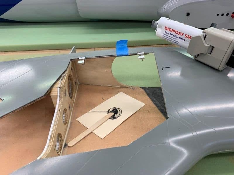
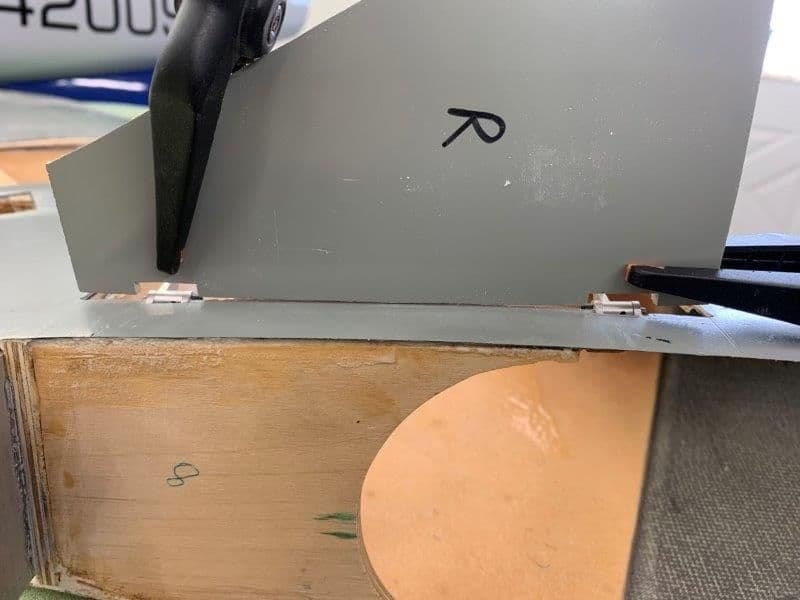
Setting gear doors on struts
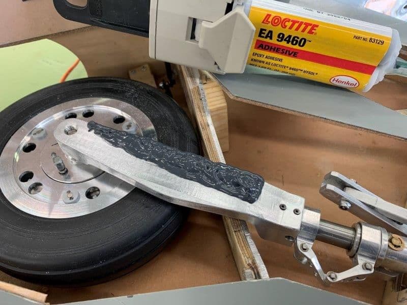
I gave each strut a full coat of Vaseline as a release agent. Then I used a bed of hysol epoxy to set the gear doors onto the struts at the correct angle to be flush with the wing skin.
I filled in the gaps from the outside with hysol.
Once the epoxy cures I can pop the doors off the struts and start to fill and finish the inside of the doors. Once the inside of the doors are done I will glass and fill the outside of the doors leaving clearance for the tire to rotate. Then I can figure out how to attach the doors to the strut that will allow removal for maintenance.
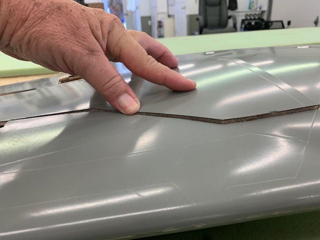
Doors are now flush with wing skins
It won't be as bad as I first thought after the outside of the doors are filled and feathered to the edges. The worst will be the angle of the door when gear is extended as the doors will be slightly towed in in relation to the strut. Its the best I can do at this point. At least the gross tow in angle of the original gear design is now fixed.
I gave each strut a full coat of Vaseline as a release agent. Then I used a bed of hysol epoxy to set the gear doors onto the struts at the correct angle to be flush with the wing skin.
I filled in the gaps from the outside with hysol.
Once the epoxy cures I can pop the doors off the struts and start to fill and finish the inside of the doors. Once the inside of the doors are done I will glass and fill the outside of the doors leaving clearance for the tire to rotate. Then I can figure out how to attach the doors to the strut that will allow removal for maintenance.
Doors are now flush with wing skins
It won't be as bad as I first thought after the outside of the doors are filled and feathered to the edges. The worst will be the angle of the door when gear is extended as the doors will be slightly towed in in relation to the strut. Its the best I can do at this point. At least the gross tow in angle of the original gear design is now fixed.
 01-26-2020, 07:59 AM
#499

Great work fixing a design issue (lemons to lemonade). One tip, when I do stuff like this I make sure to pre load the gear in the up position. I put a block of wood under the tire in the wheel bay. I have found that if I don't, just the act flipping the wrong over, (gravity) will pull the wheel out some (ruining the careful door fit) due to the slop in the gear mechanism. Maybe your gear don't do this. Great work in any case