


Ultimate Jets projects for 2019

 09-23-2018, 05:56 AM
#27

Thread Starter

Too bad we were too busy to catch up for dinner.
Maybe at Top Gun or Florida Jets?
09-23-2018, 06:01 AM
#28
Thread Starter
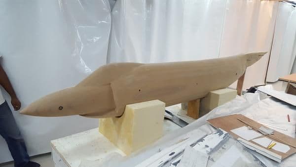
Here is a picture of the Demon fuselage plug.
The canopy is a rough cut and is being re-done at the moment. The one shown here is too small and has a wrong transition at the top.
The canopy is a rough cut and is being re-done at the moment. The one shown here is too small and has a wrong transition at the top.
09-23-2018, 10:54 AM
#30

My Feedback: (23)
Your comment is stupid. Specifically the inbred part. Kind of flying Nazi emblem aircraft at events. You just don't see it. Glad I got rid of mine. To each their own but I won't look at any of them and that's my choice.
Last edited by ledd4u; 09-23-2018 at 11:11 AM.
 09-23-2018, 03:51 PM
#34
look whats the 2nd photo... a FW190 with a swastika.. gasp!
https://photos.google.com/share/AF1Q...VVRXlrbXdtMmxB
 09-27-2018, 02:09 PM
#36
My Feedback: (23)
im sorry your blind.
look whats the 2nd photo... a FW190 with a swastika.. gasp!
https://photos.google.com/share/AF1Q...VVRXlrbXdtMmxB
09-29-2018, 04:38 AM
#37
Thread Starter
I am moving a bit backwards into the Demon genesis story.
Here are some more CAD rendering from Siemens NX12 and some explanations.
The plane will be very easy to ship and transport.
The fuselage will be split in 3 parts. Wings, fin, stabilizers will be removable.
The fuselage will break into: nose section, cut at the main panel line in front of the wing, middle section excluding the beaver tail, and rear section ( essentially the beaverr tail itself ). The rear section will split just at the tailpipe.
The wing will have two 30 mm carbon tubes. The rear main tube will be a single 3 foot piece ( that passes just below the thrust tube ). The carbon sleeve will be ceramic coated and aluminum shielded to avoid heat transfer.
The front wing tube will stop at the engine bypass section.
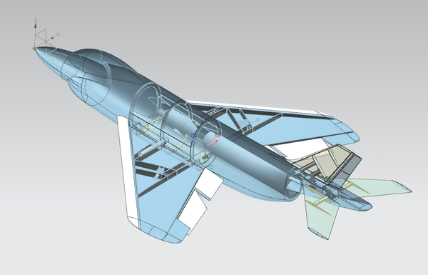
The engine and fuel tank will be located exactly on the CG.
The plane is designed for a 120-140 class powerplant and is designed for 15 g load at 16 kgs takeoff weight.
Tank size will be 5 liters. A smaller/ lighter plasma bag option will be available for 13.5 kg class scale competition.
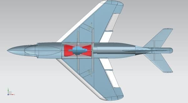
The flight controls are:
2 stabilizers, 1 rudder, 2 slats, 2 flaps, 2 ailerons, 1 steering. or 10 servos.
The flaps, ailerons and slats will be live hinged, like our Crusader, with our Gorillahinge system ( a polymer infused fabric that sustains 200 kg.cm of tear force ). They will include an aerodynamic seal surface, like the Crusader.
All control links will be hidden.
The tail section ( beaver tail ) will be removable and include the fin support, stabilizer support and fin/ stabilizers servos.
A large hatch will be located at the top of the beaver tail to give access to the 3 servos.
The stabilizer and rudder controls links will be hidden.
The rudder will be controlled with a torque rod system that slides in a slot at the bottom of the surface.

The tail section will connect to the center section with 4 screws and 3 carbon tubes to ensure perfect rigidity and pitch/ yaw precision.
Al large bearing system will be set this section, between two carbon fiber bulkhead.
The two stabilizer servos will be relatively close to the shafts.
The rudder servo will located at the center, in front of the stabilizer servos.

The stabilizer shafts will be made of Alcoa Al 2028 12 mm rods. The will have a key system to permanently lock the arms.
The control arms will be keyed/ clamped with a M3 socket head screw.
The shafts will be supported by two ultra high tolerance 12 mm needle bearings each. These sustain 500 lbs each.
The bearing block is a billet milled Al 7075 unit that is sandwiched between two carbon fiber bulkheads.
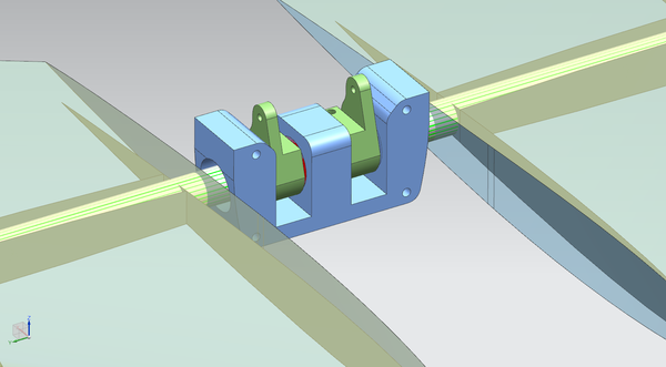
This assembly is exactly the same as for our 1/7 scale Crusader and has proven to be absolutely bullet proof.
Here are some more CAD rendering from Siemens NX12 and some explanations.
The plane will be very easy to ship and transport.
The fuselage will be split in 3 parts. Wings, fin, stabilizers will be removable.
The fuselage will break into: nose section, cut at the main panel line in front of the wing, middle section excluding the beaver tail, and rear section ( essentially the beaverr tail itself ). The rear section will split just at the tailpipe.
The wing will have two 30 mm carbon tubes. The rear main tube will be a single 3 foot piece ( that passes just below the thrust tube ). The carbon sleeve will be ceramic coated and aluminum shielded to avoid heat transfer.
The front wing tube will stop at the engine bypass section.
The engine and fuel tank will be located exactly on the CG.
The plane is designed for a 120-140 class powerplant and is designed for 15 g load at 16 kgs takeoff weight.
Tank size will be 5 liters. A smaller/ lighter plasma bag option will be available for 13.5 kg class scale competition.
The flight controls are:
2 stabilizers, 1 rudder, 2 slats, 2 flaps, 2 ailerons, 1 steering. or 10 servos.
The flaps, ailerons and slats will be live hinged, like our Crusader, with our Gorillahinge system ( a polymer infused fabric that sustains 200 kg.cm of tear force ). They will include an aerodynamic seal surface, like the Crusader.
All control links will be hidden.
The tail section ( beaver tail ) will be removable and include the fin support, stabilizer support and fin/ stabilizers servos.
A large hatch will be located at the top of the beaver tail to give access to the 3 servos.
The stabilizer and rudder controls links will be hidden.
The rudder will be controlled with a torque rod system that slides in a slot at the bottom of the surface.
The tail section will connect to the center section with 4 screws and 3 carbon tubes to ensure perfect rigidity and pitch/ yaw precision.
Al large bearing system will be set this section, between two carbon fiber bulkhead.
The two stabilizer servos will be relatively close to the shafts.
The rudder servo will located at the center, in front of the stabilizer servos.
The stabilizer shafts will be made of Alcoa Al 2028 12 mm rods. The will have a key system to permanently lock the arms.
The control arms will be keyed/ clamped with a M3 socket head screw.
The shafts will be supported by two ultra high tolerance 12 mm needle bearings each. These sustain 500 lbs each.
The bearing block is a billet milled Al 7075 unit that is sandwiched between two carbon fiber bulkheads.
This assembly is exactly the same as for our 1/7 scale Crusader and has proven to be absolutely bullet proof.
Last edited by olnico; 09-29-2018 at 04:41 AM.
10-11-2018, 10:42 PM
#39
Thread Starter
Here are a few pictures of the raw plug cutting process before surface finish.
Plates of milling material are aligned on our fast processing router, vacuum clamped and cut in slices that will be glued together at a later stage.

Here is an example showing the female plug wing mold. The hollow shape allows for a reduction of material cost, mold weight and cutting time of about 30%.
For the flying surfaces, we process negative molds to make a composite positive plug. This allows us to work safely on thin trailing edges without braking them, as we have an extensive surface work going on with these parts.

Here are the negative molds completely cut out of the Kuka robot.

Another shot of the male fuselage plug shape being milled on the Kuka. These are the half beaver tail parts. These specific parts are milled from two faces. The negative exhaust radius has too much angle for the water cooled 30 KW exo bearing milling monster head to do its job in one setting without collisions.

We have two Kuka milling robots at the factory. One two ton KR240 on a fixed base and one 4 ton KR320 on a 30 meter long rail. We exclusively use the KR240 at Enata Aerospace as it allows a milling precision of 1/15 mm within a half sphere of 3 meters diameter.
Plates of milling material are aligned on our fast processing router, vacuum clamped and cut in slices that will be glued together at a later stage.
Here is an example showing the female plug wing mold. The hollow shape allows for a reduction of material cost, mold weight and cutting time of about 30%.
For the flying surfaces, we process negative molds to make a composite positive plug. This allows us to work safely on thin trailing edges without braking them, as we have an extensive surface work going on with these parts.
Here are the negative molds completely cut out of the Kuka robot.
Another shot of the male fuselage plug shape being milled on the Kuka. These are the half beaver tail parts. These specific parts are milled from two faces. The negative exhaust radius has too much angle for the water cooled 30 KW exo bearing milling monster head to do its job in one setting without collisions.
We have two Kuka milling robots at the factory. One two ton KR240 on a fixed base and one 4 ton KR320 on a 30 meter long rail. We exclusively use the KR240 at Enata Aerospace as it allows a milling precision of 1/15 mm within a half sphere of 3 meters diameter.
11-04-2018, 04:31 AM
#40
Thread Starter
Here is some update on the Demon tooling production, with some details on the wing plug molds production.
The tooling board is cut 0.5 mm wider than the finished shape. The mold is then pressure gun sprayed with a milling fairing compound at 1 mm thickness. After curing, the shape is finished to final dimension with thin passes.


The tooling board is cut 0.5 mm wider than the finished shape. The mold is then pressure gun sprayed with a milling fairing compound at 1 mm thickness. After curing, the shape is finished to final dimension with thin passes.
11-05-2018, 09:18 PM
#44
Thread Starter
Here is a video of a tricky part to machine: the negative angle of the Demon beaver tail.
The video shows the kuka CAM accelerated simulation, then the real life machining.
<iframe src="https://player.vimeo.com/video/298833959" width="640" height="1138" frameborder="0" webkitallowfullscreen mozallowfullscreen allowfullscreen></iframe>
The video shows the kuka CAM accelerated simulation, then the real life machining.
<iframe src="https://player.vimeo.com/video/298833959" width="640" height="1138" frameborder="0" webkitallowfullscreen mozallowfullscreen allowfullscreen></iframe>
11-06-2018, 02:38 PM
#45

https://www.centralfloridasports.com...2-oclock-high/
Kidding aside, on what level are you equating cold war era MiGs with swastikas? Or is it just any aircraft representing an adversary in a past conflict? What about a Fokker Dr.1?
11-23-2018, 11:08 PM
#47
Thread Starter
Here are some details about the F-3H Demon fuselage plug assembly.
The Fuselage plug inner core was milled with matching alignment holes. These holes allow the insertion of M10 threaded rods that serve two purposes: aligning the two halves and pressing them together at the gluing stage.
Before gluing, the halves are aligned and measurements are taken to verify the width of the plug. It is not uncommon that milling deviations create an offset in the parting plan, thickening the two halves . This is easily detected by verifying the plug width once assembled. Here are a few pictures of the plug after gluing.
Here is a view from the front that shows the alignment of the seam line.

The same view front the back, that shows the alignment of the beaver tail flat surfaces.

And a side view of the nose area. The threaded rod that presses the front halves is visible here, as well as the flatness of the canopy surface.

The Fuselage plug inner core was milled with matching alignment holes. These holes allow the insertion of M10 threaded rods that serve two purposes: aligning the two halves and pressing them together at the gluing stage.
Before gluing, the halves are aligned and measurements are taken to verify the width of the plug. It is not uncommon that milling deviations create an offset in the parting plan, thickening the two halves . This is easily detected by verifying the plug width once assembled. Here are a few pictures of the plug after gluing.
Here is a view from the front that shows the alignment of the seam line.
The same view front the back, that shows the alignment of the beaver tail flat surfaces.
And a side view of the nose area. The threaded rod that presses the front halves is visible here, as well as the flatness of the canopy surface.
11-24-2018, 06:29 AM
#49
Thread Starter
It is a weird looking airplane, indeed. But it has grown on me tremendously. I actually find it very impressive and I really like the old fashion shape. Like the F-4D Skyray...
12-30-2018, 03:13 AM
#50
Thread Starter
Here are a couple of pictures of the wing plugs manufacture.
1. The wing plug molds buffed and ready to laminate

The lamination process:

And the wing plugs released:

1. The wing plug molds buffed and ready to laminate
The lamination process:
And the wing plugs released: