1/7 Scale Blackburn Buccaneer All Composite Scratch Build
 08-24-2019, 09:37 AM
#301

Dave,
No, I haven't as of yet, but I think I probably could. I have enough parts complete and the fuselage internal design is fairly mature to generate an initial estimate.
I will probably start a weight & balance estimate to see how bad it might be.
Paul
No, I haven't as of yet, but I think I probably could. I have enough parts complete and the fuselage internal design is fairly mature to generate an initial estimate.
I will probably start a weight & balance estimate to see how bad it might be.
Paul
 08-30-2019, 11:02 AM
#302
At Dave's suggestion I have started to build a Weight & Balance spreadsheet. It's just over 100 lines long so far with each component listed along with estimated weights and individual c.g. locations. As I have the final parts I am replacing the estimates with actual weights.
The biggest uncertainty right now is in the weight of the main fuselage sections. My WAG entries for those total almost 20lb, but I feel that I can significantly improve on those weights.
The overall good news is that I'm tracking to my original 50lb dry target, and it is currently looking like I will need around 1lb of nose ballast. I'm sure the c.g. will follow the habit of racing towards the tail as time progresses........
I'm using the full-scale c.g. range from the maintenance manual, which gives me a 36mm spread (1294-1330mm from the tip of radome). I will double check the location and maybe make a foam chuck-glider as a further validation that the c.g. is in the approximately correct location.
Paul
08-30-2019, 06:14 PM
#304
Exactly - fingers crossed.
In reality I expect some significant nose ballast will have to be added. Too late to turn back now!!!
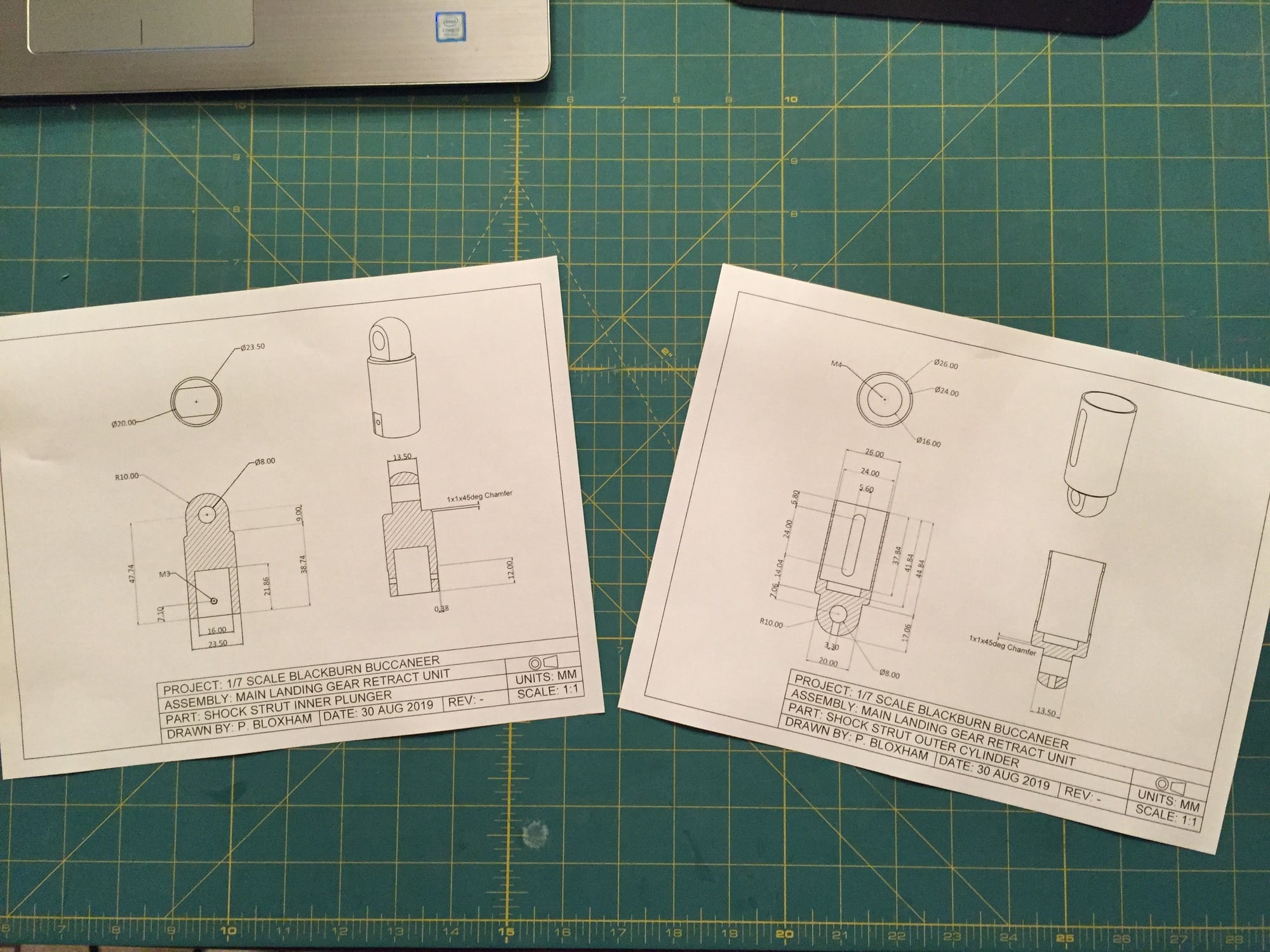
The design for the revised shock struts are complete. I have just ordered some more AL 7075 so that I can start to make them. This version gets over double the travel of the prototype shock struts.
Paul
In reality I expect some significant nose ballast will have to be added. Too late to turn back now!!!
The design for the revised shock struts are complete. I have just ordered some more AL 7075 so that I can start to make them. This version gets over double the travel of the prototype shock struts.
Paul
08-30-2019, 10:09 PM
#305

Paul
Why such a big clearance on the piston rod? 0.5 and such a thin wall on the outer tube, I’m sure the piston will rock, grab and ravel the outer tube.
Dave
Why such a big clearance on the piston rod? 0.5 and such a thin wall on the outer tube, I’m sure the piston will rock, grab and ravel the outer tube.
Dave
 08-31-2019, 07:00 AM
#307
Dave,
One of the prototypes had more than 0.5mm due to my lack of machining skills and appears to be fine.Based on that, I think 0.5mm (0.25mm all the way around) would be fine, but I have updated the design to close the gap down to 0.1mm around.
How accurately I can turn them is another matter")
Also drilled out the inner plunger some more to save weight.
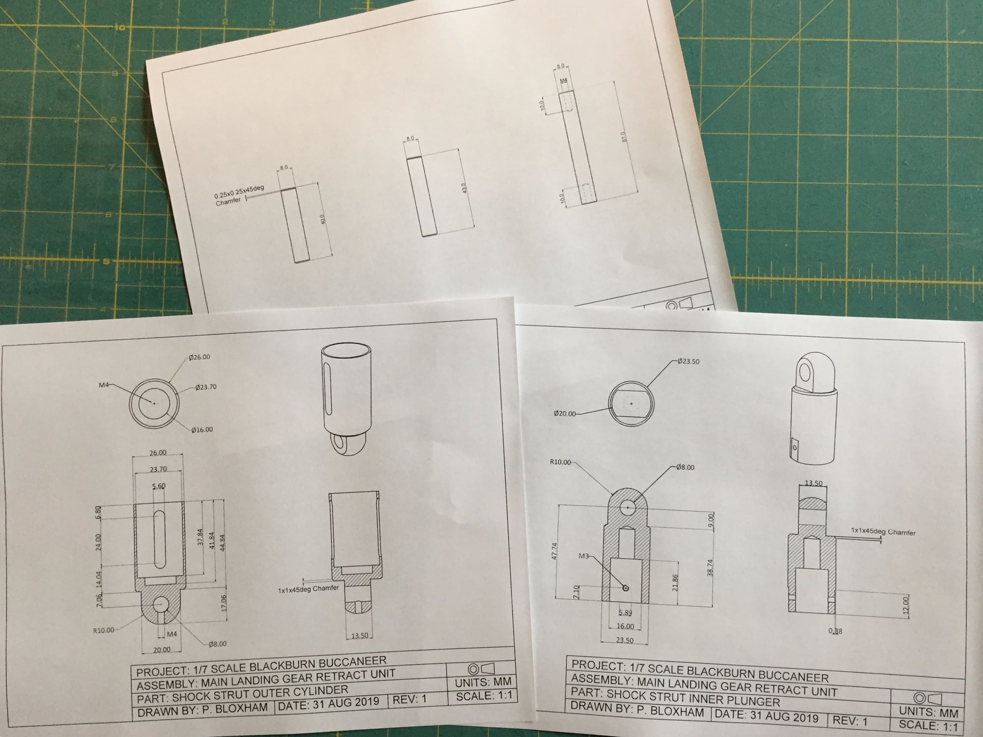
One of the prototypes had more than 0.5mm due to my lack of machining skills and appears to be fine.Based on that, I think 0.5mm (0.25mm all the way around) would be fine, but I have updated the design to close the gap down to 0.1mm around.
How accurately I can turn them is another matter
Also drilled out the inner plunger some more to save weight.
09-01-2019, 04:14 AM
#308
Moving slowly in and out won't be the issue, but a landing shock the plunger will not move smoothly, if it rocks it will try and burst out the side of the guide tube. I'm sure based on everything we see, you are more than capable of machining as required....
Dave
Dave
 09-13-2019, 06:29 PM
#310
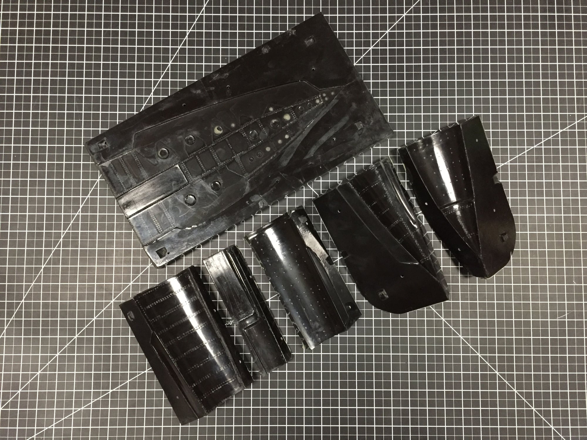
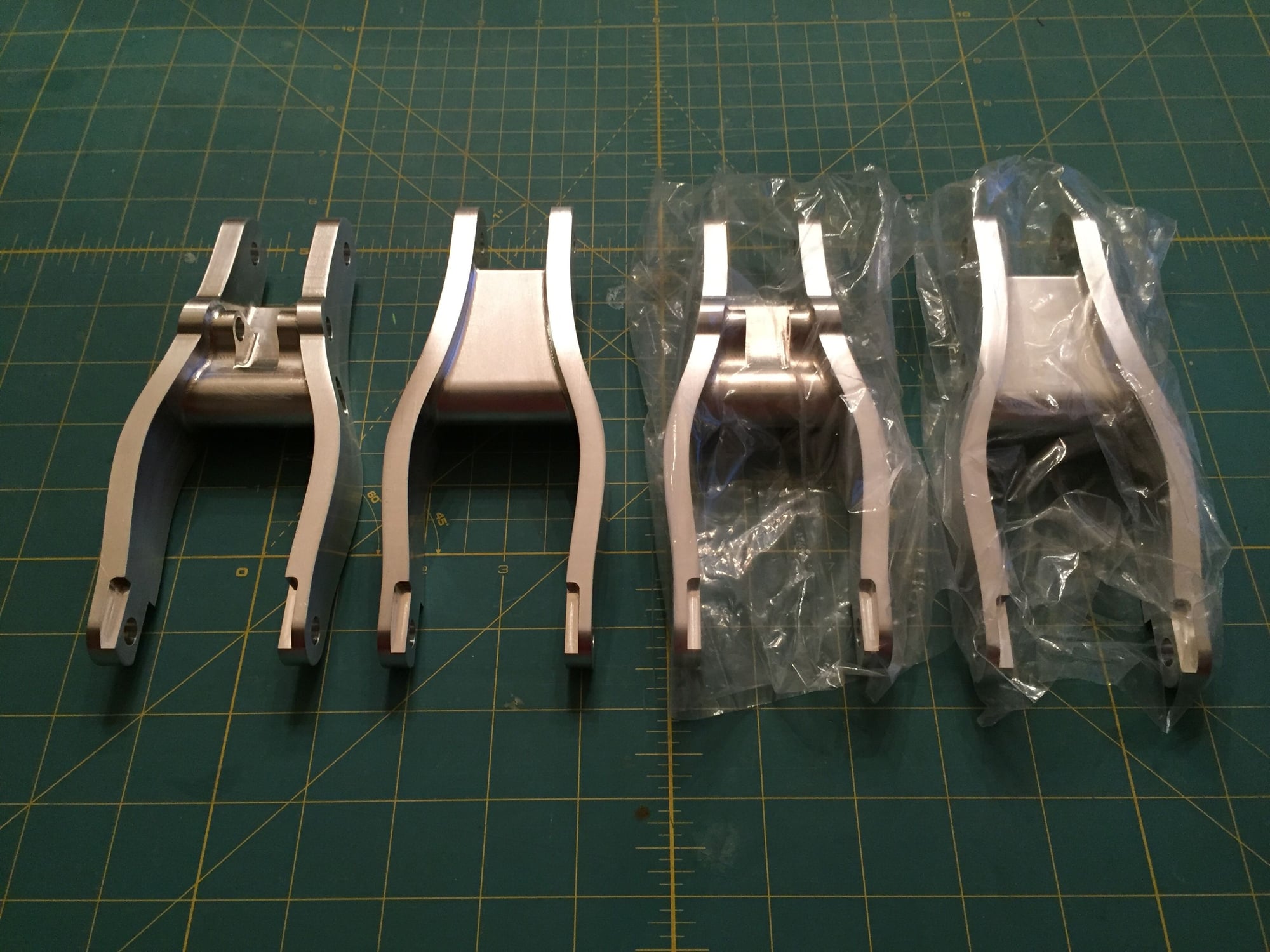
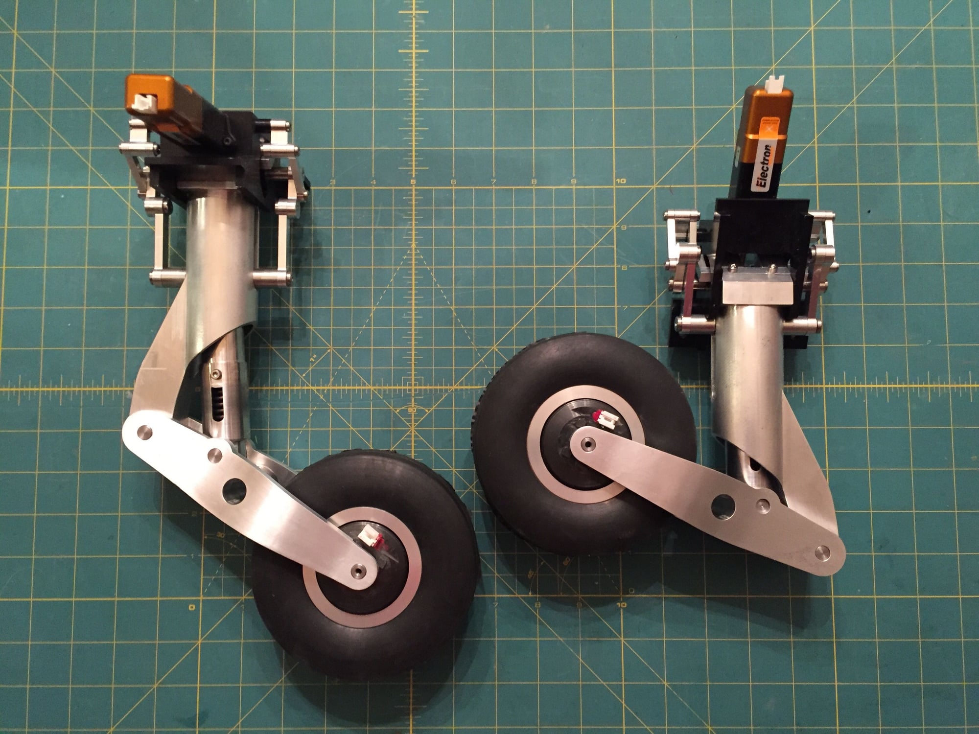
I've finished the v2 shock struts. With this new design I managed to increase the shock strut travel from 9mm to 24mm, using the full capability of the spring. Bottoming load should now be over double the weight of the model.
The new shock struts look much better and have a more scale appearance.
I am now just waiting on the trailing link arms to come back from machining and the main gear will be complete.
Paul
The new shock struts look much better and have a more scale appearance.
I am now just waiting on the trailing link arms to come back from machining and the main gear will be complete.
Paul

 09-22-2019, 08:16 AM
#314
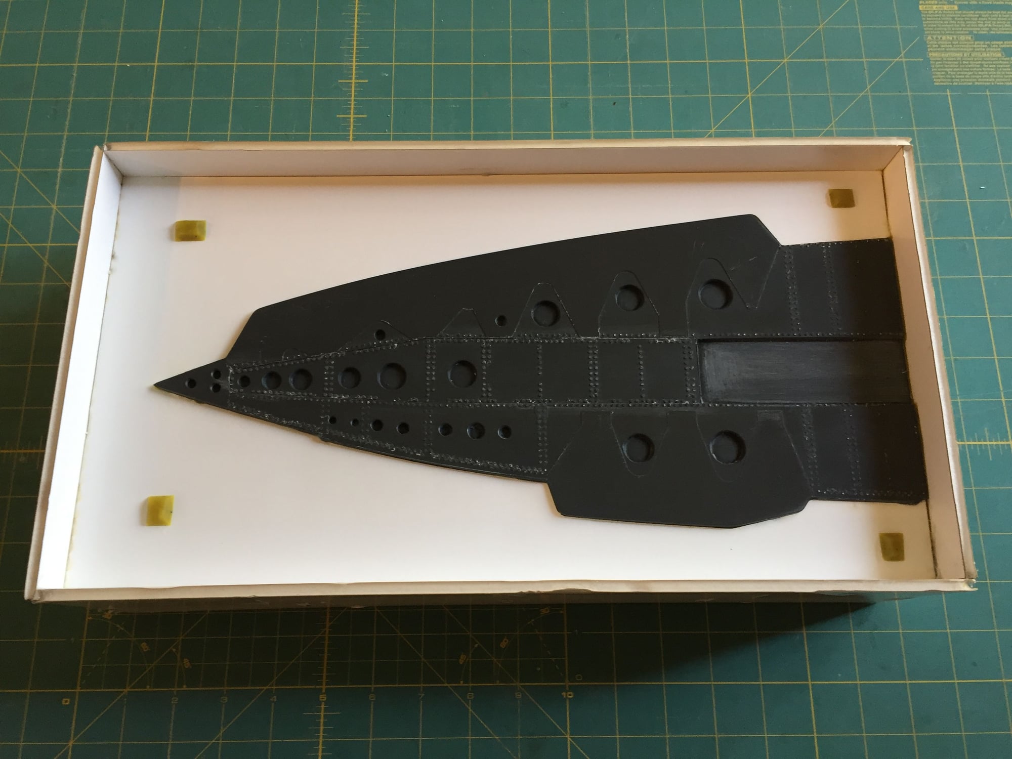
Also started on the layout of the forward fuselage, including reserving the volume for the cockpit. I found an error with the nose gear door recess, and I'll have to extend it aft 25mm to clear the nose gear sweep. Glad I found that now rather than once I made the mold.
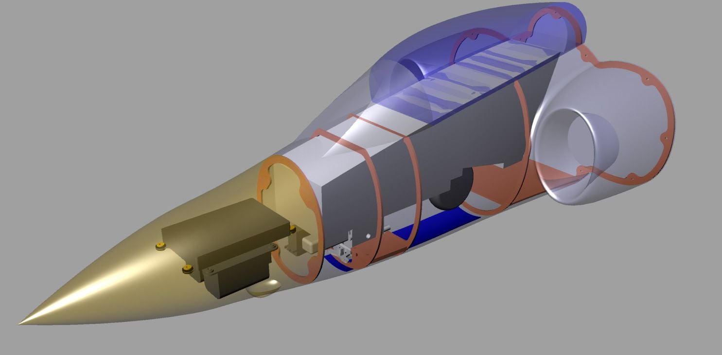
Paul
Paul
Last edited by JSF-TC; 09-22-2019 at 08:21 AM.
10-03-2019, 04:02 PM
#315
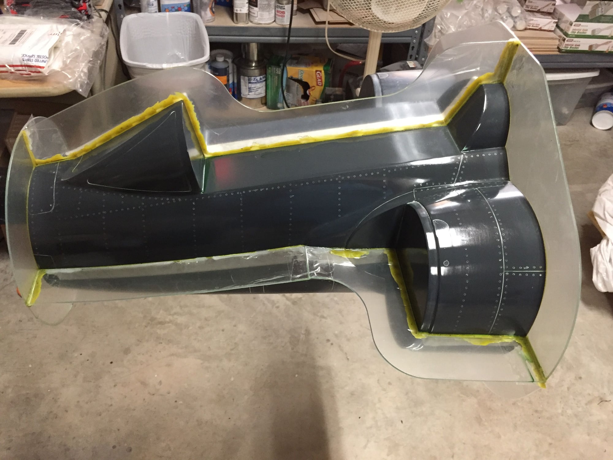
After discovering that I needed to extend the nose gear door recess to allow for the gear to retract I did a quick modification to the plug. After cutting out the offending area I back filled it with body filler and sanded it smooth before a final covering of Duratec surface primer.
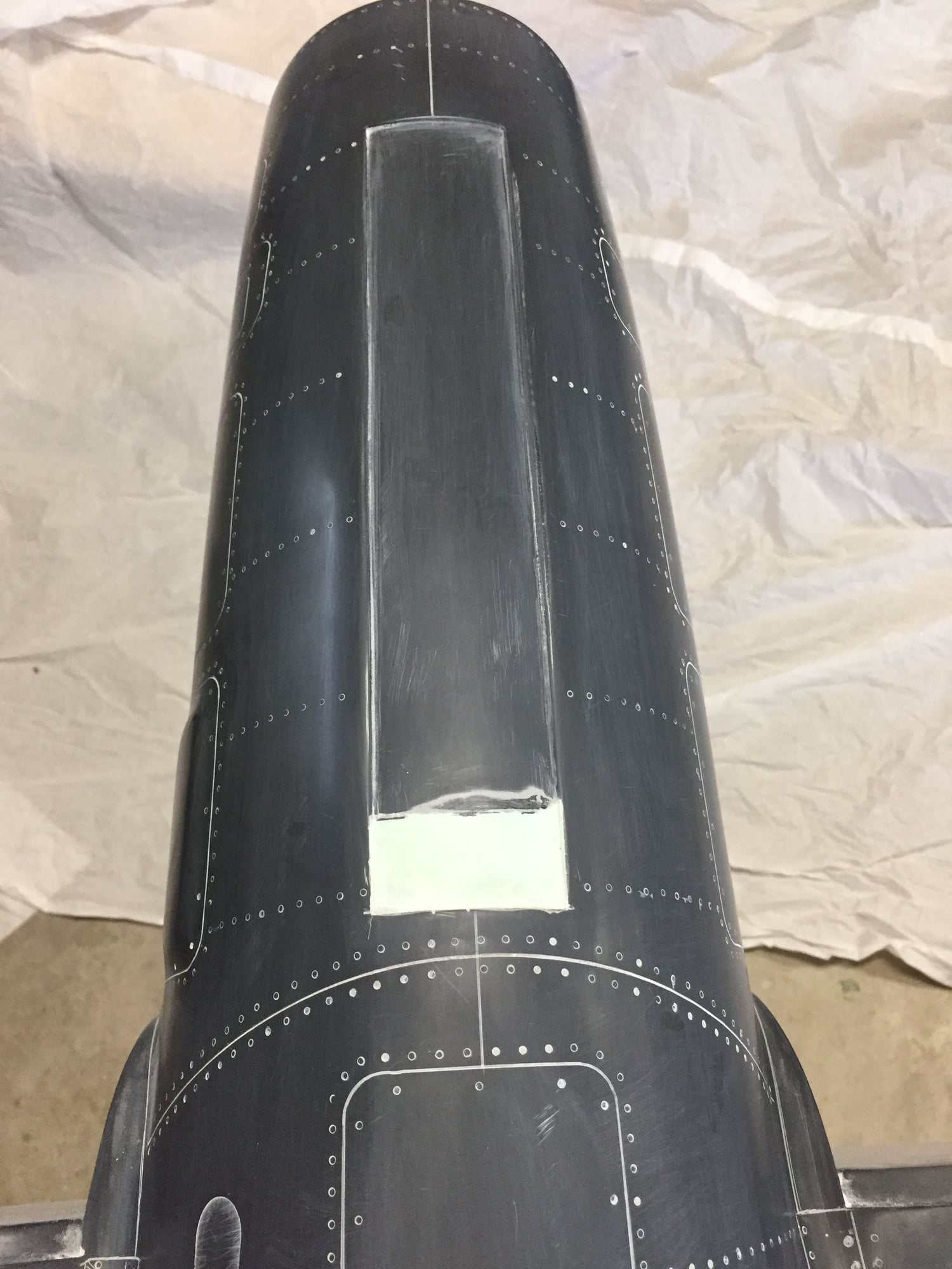
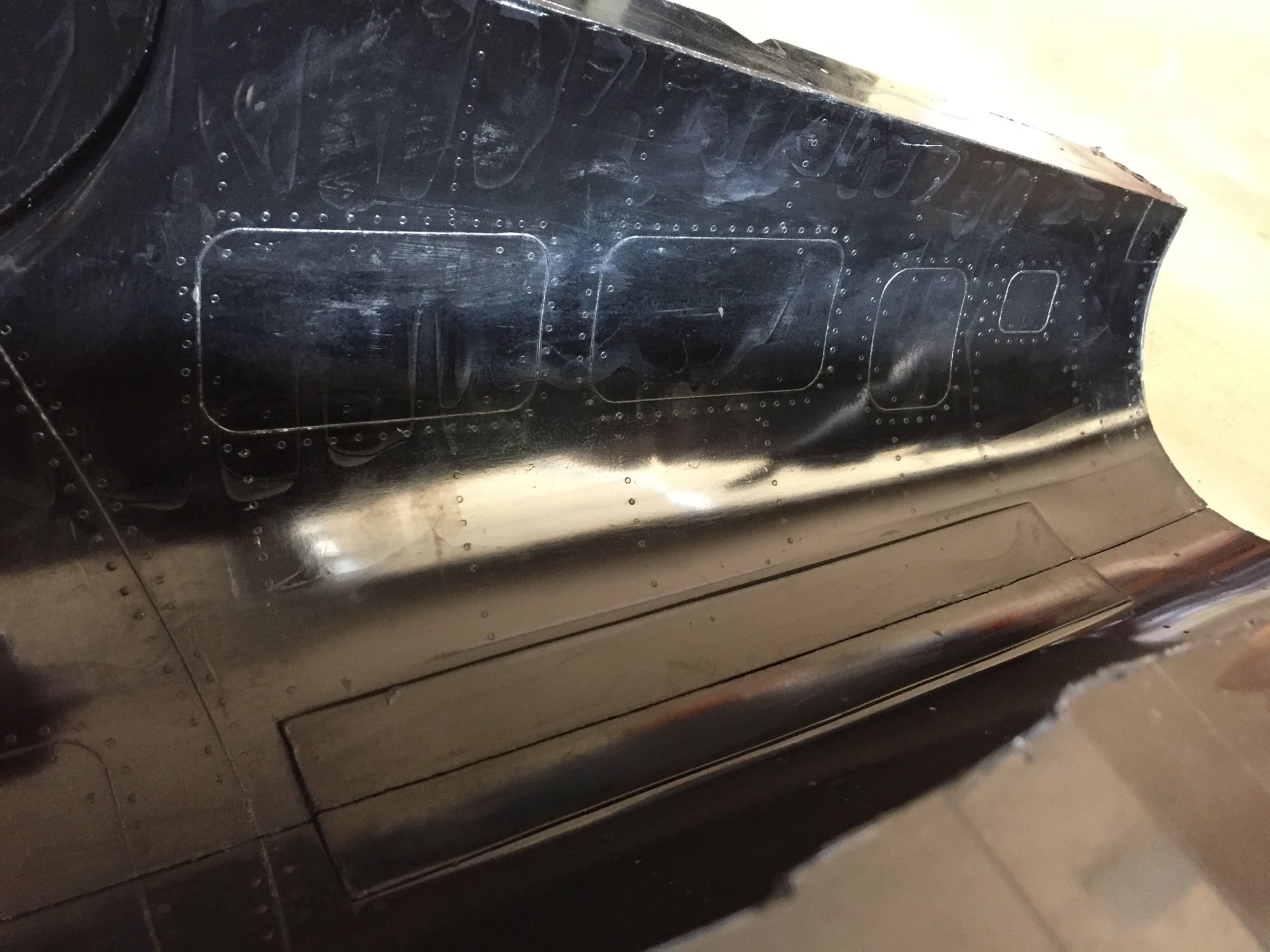
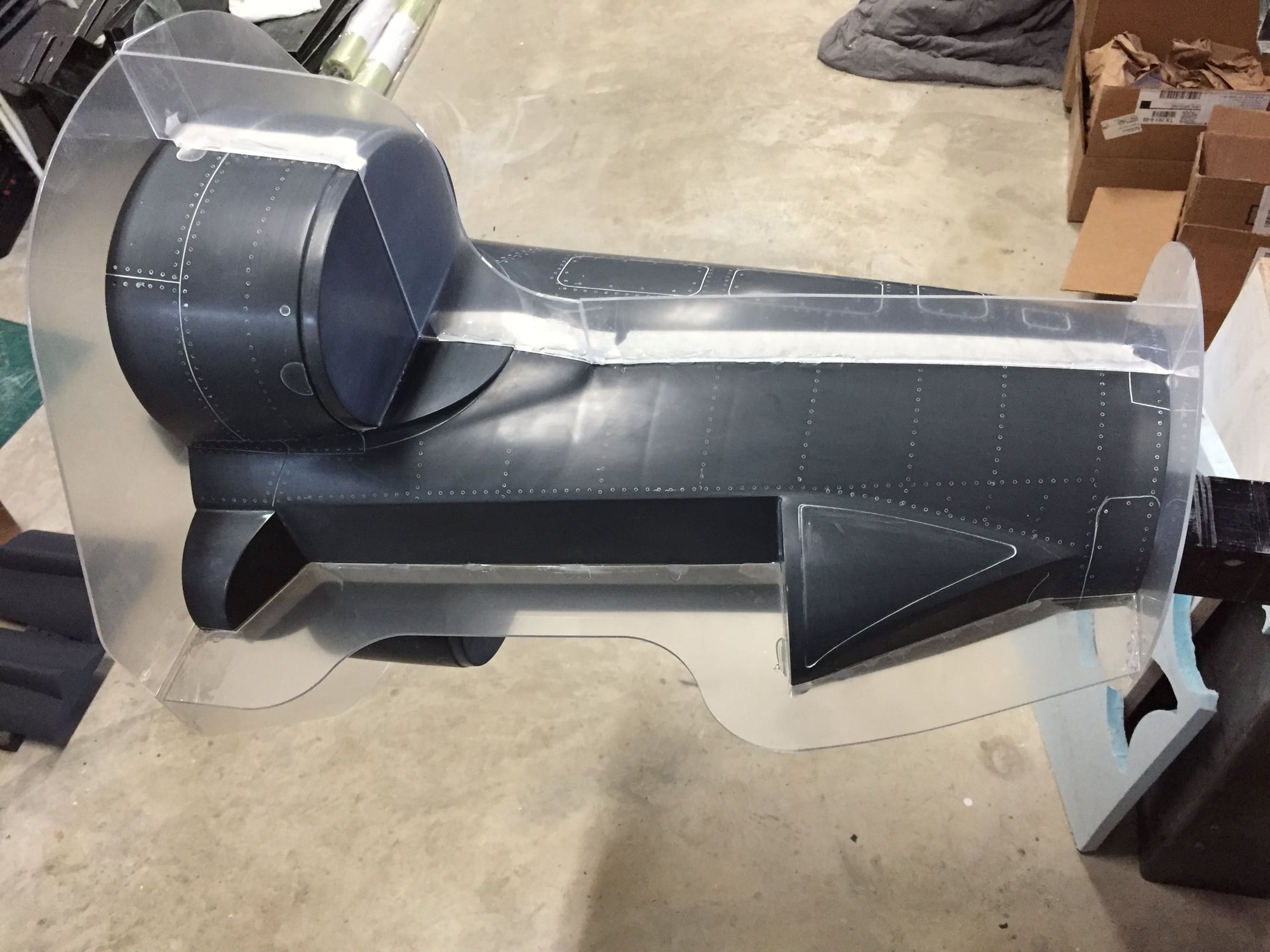
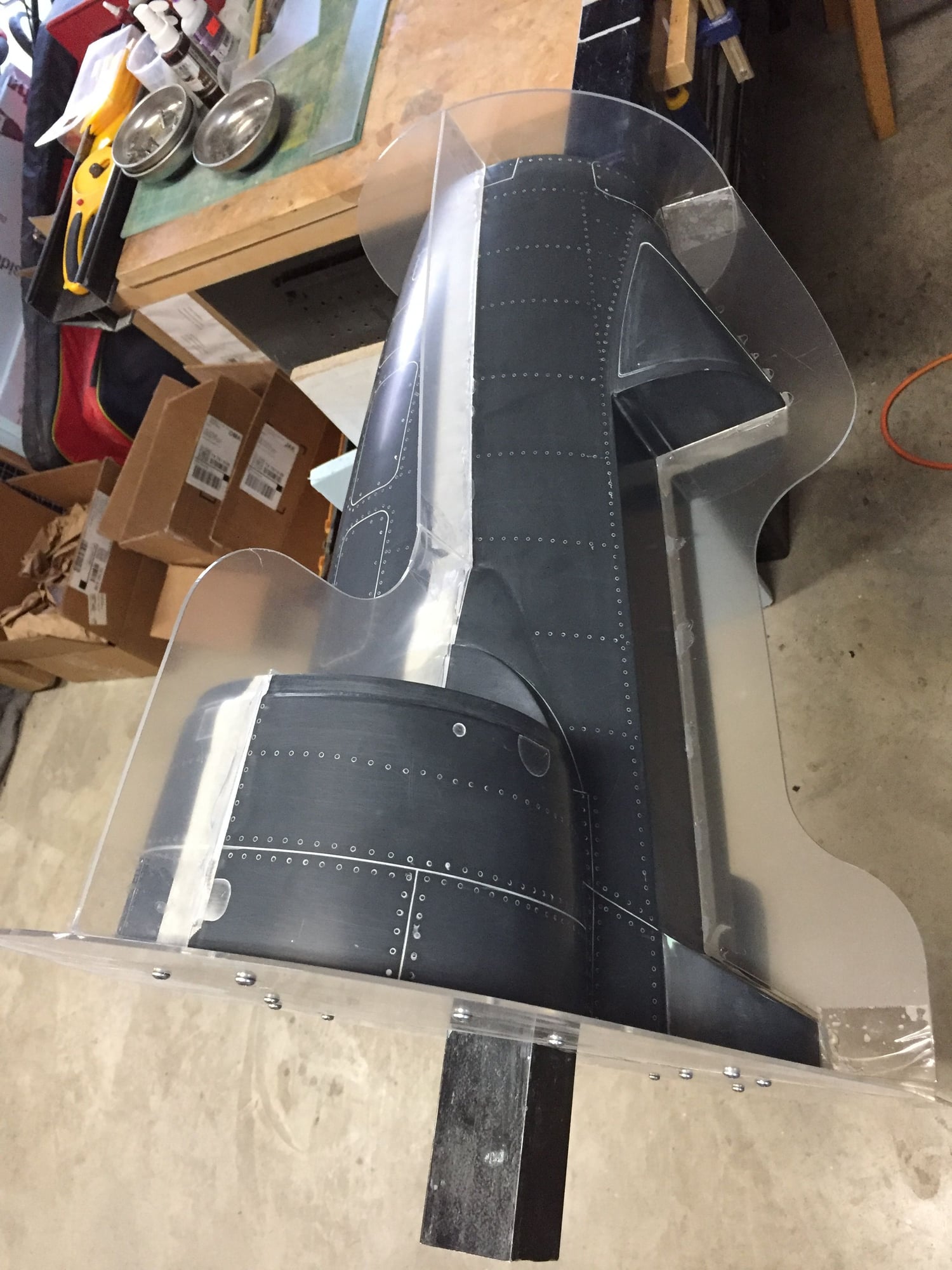
I then moved on to forming the parting planes for the forward fuselage, cut out of 2mm perspex. Front and rear flanges were screwed onto the plug and the first quarter of the mold frame was set up, hot glued onto masking tape placed on the mold. Gaps were then filled with the molding clay. Finally the plug was waxed and PVA'd ready for making the mold.
Starting to see a little bit of the plug shrinkage showing up with the underlying plug construction becoming visible in the surface reflection. Can't feel it so I hope it will not be noticeable in the final part. It's a shame the plug construction doesn't line up with the scale rivet lines.
Paul
Last edited by JSF-TC; 10-03-2019 at 04:05 PM.
10-03-2019, 11:10 PM
#317
After discovering that I needed to extend the nose gear door recess to allow for the gear to retract I did a quick modification to the plug. After cutting out the offending area I back filled it with body filler and sanded it smooth before a final covering of Duratec surface primer.
I then moved on to forming the parting planes for the forward fuselage, cut out of 2mm perspex. Front and rear flanges were screwed onto the plug and the first quarter of the mold frame was set up, hot glued onto masking tape placed on the mold. Gaps were then filled with the molding clay. Finally the plug was waxed and PVA'd ready for making the mold.
Starting to see a little bit of the plug shrinkage showing up with the underlying plug construction becoming visible in the surface reflection. Can't feel it so I hope it will not be noticeable in the final part. It's a shame the plug construction doesn't line up with the scale rivet lines.
Paul
 10-07-2019, 05:13 PM
#320
Progress on a couple of fronts.
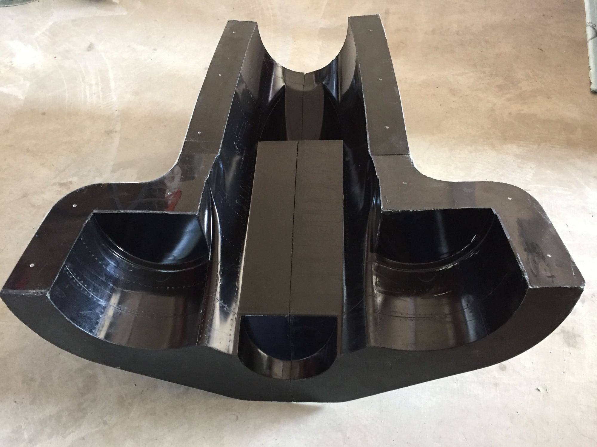
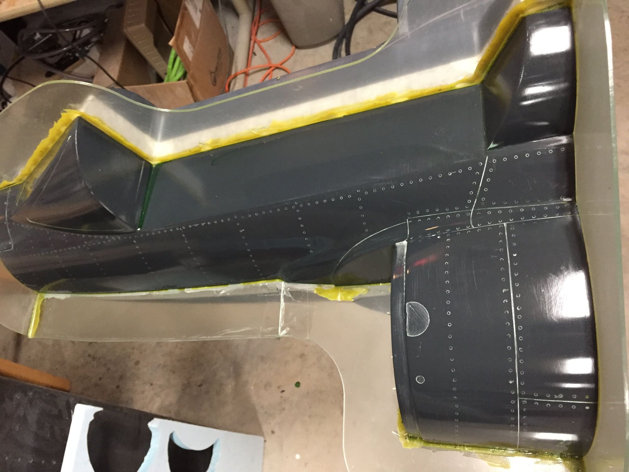
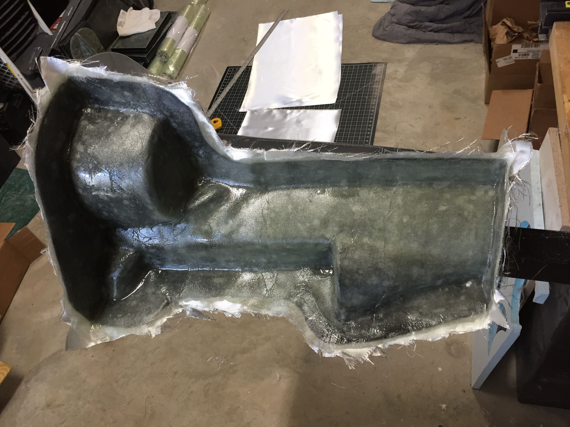
In the middle of laying up the forward fuselage mold. The first 1/4 is done, and about to lay down the glass for the next 2 quarters.
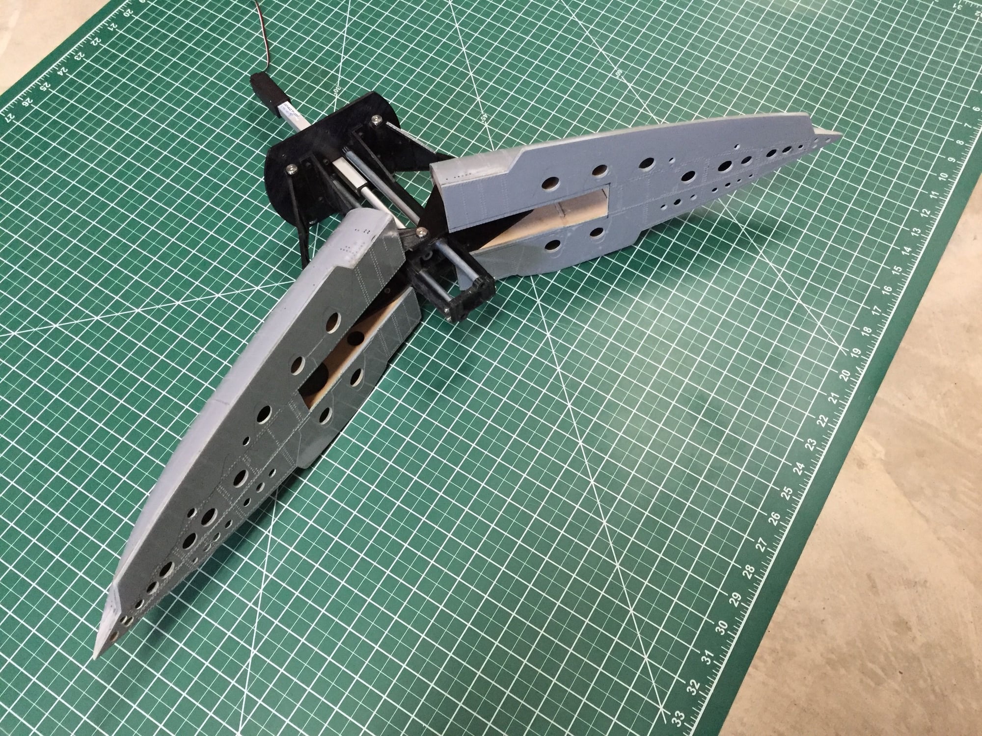
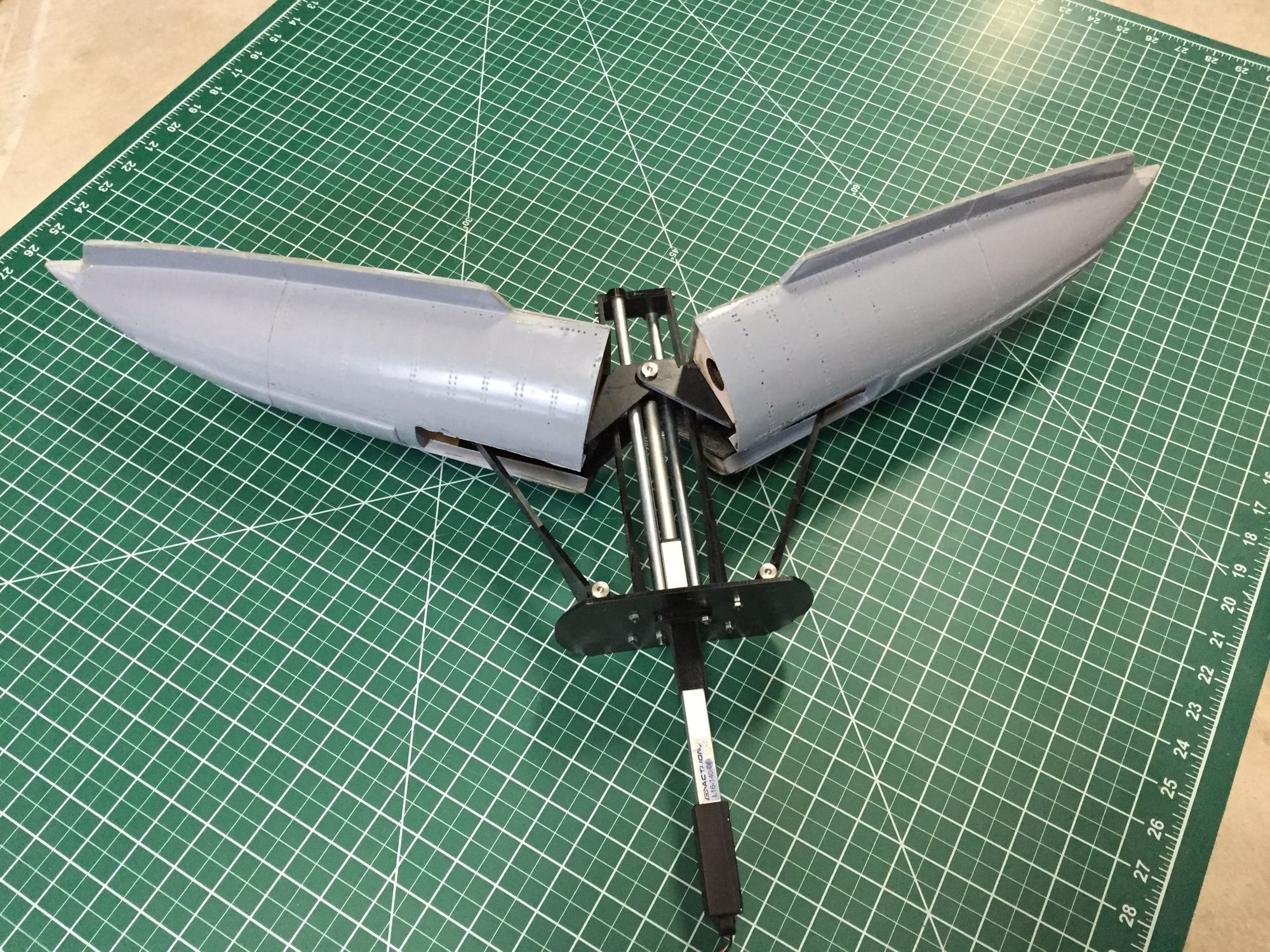
The final parts for the main gear arrived today. They look amazing. After reaming out the holes, all the parts fit together perfectly. Main gear is essentially done.
Paul
In the middle of laying up the forward fuselage mold. The first 1/4 is done, and about to lay down the glass for the next 2 quarters.
The final parts for the main gear arrived today. They look amazing. After reaming out the holes, all the parts fit together perfectly. Main gear is essentially done.
Paul
 10-13-2019, 07:49 AM
#324
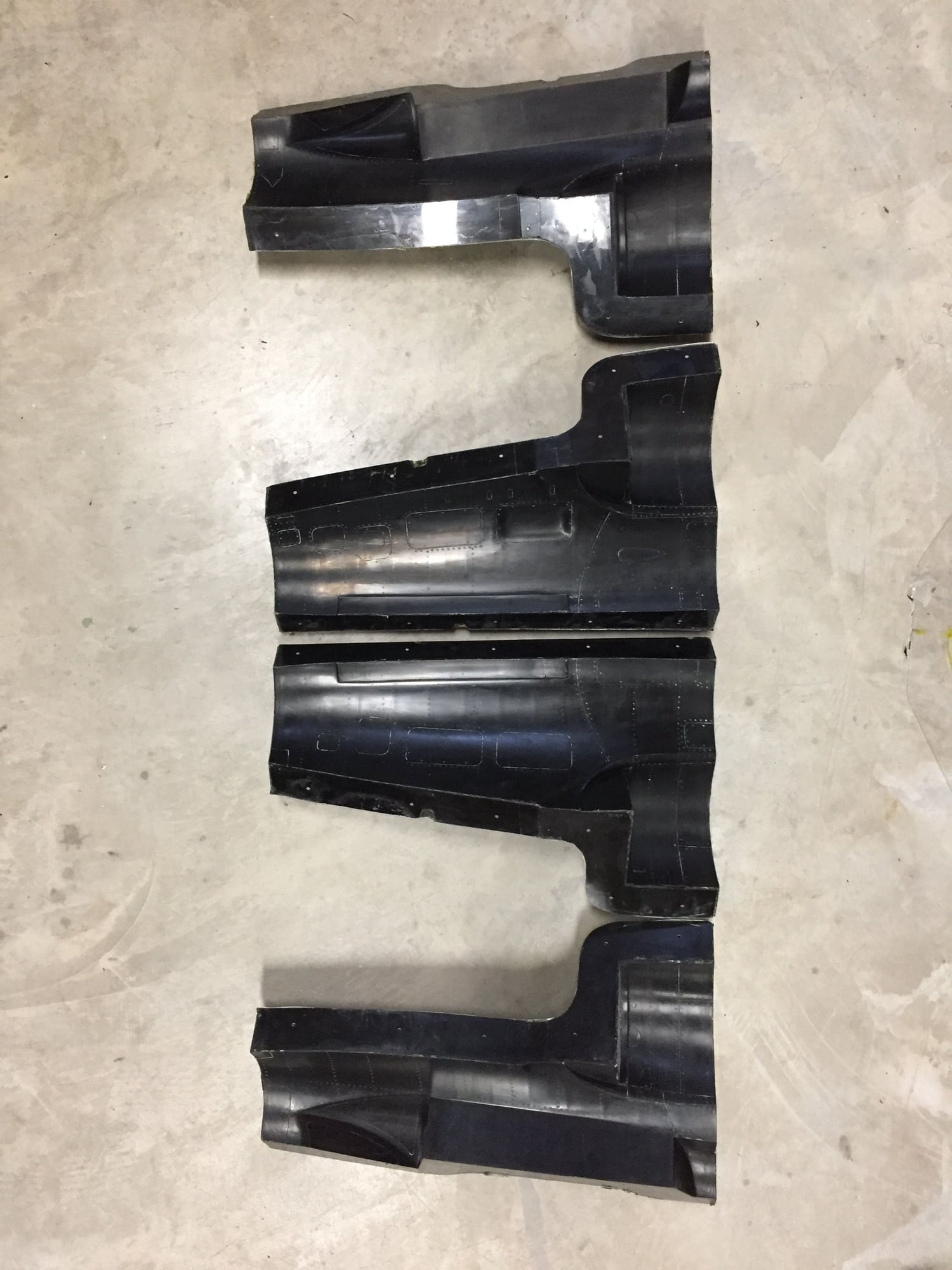
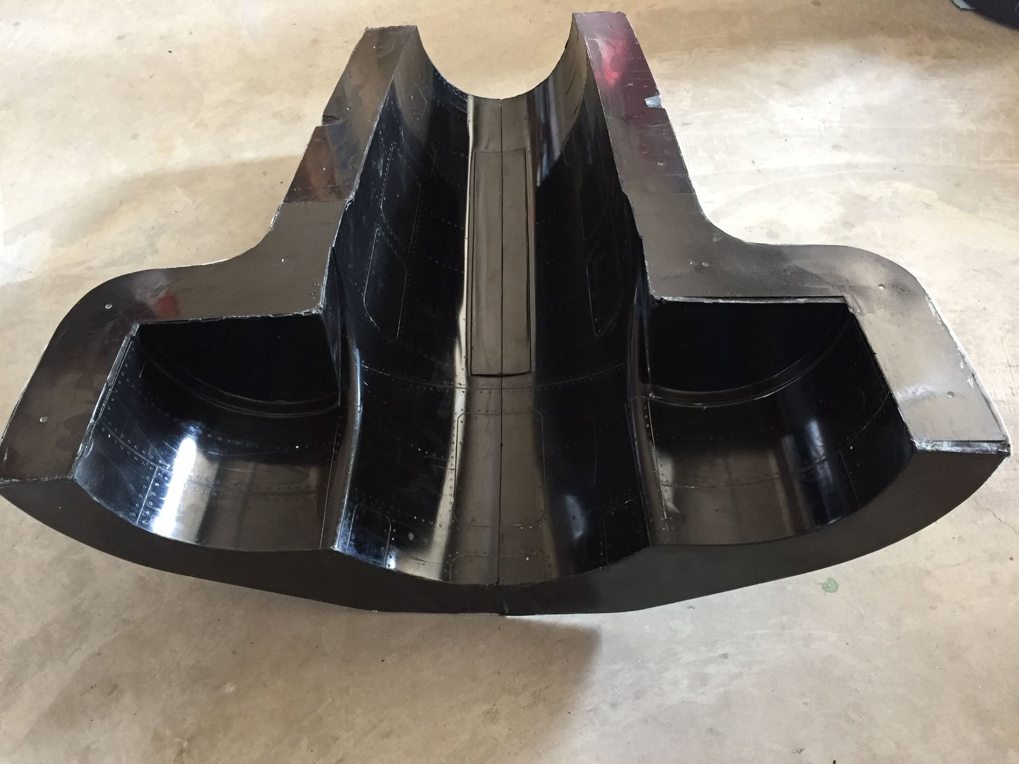
The forward fuselage molds are complete. They came off very easily and with no damage to the plug. I proved that a 2 piece mold would have worked, but I was more comfortable with making it in 4 pieces. The actual lay-up will be done as 2 pieces (top & bottom) before joining.