


1/7 Scale Blackburn Buccaneer All Composite Scratch Build
 10-30-2018, 02:27 PM
#76

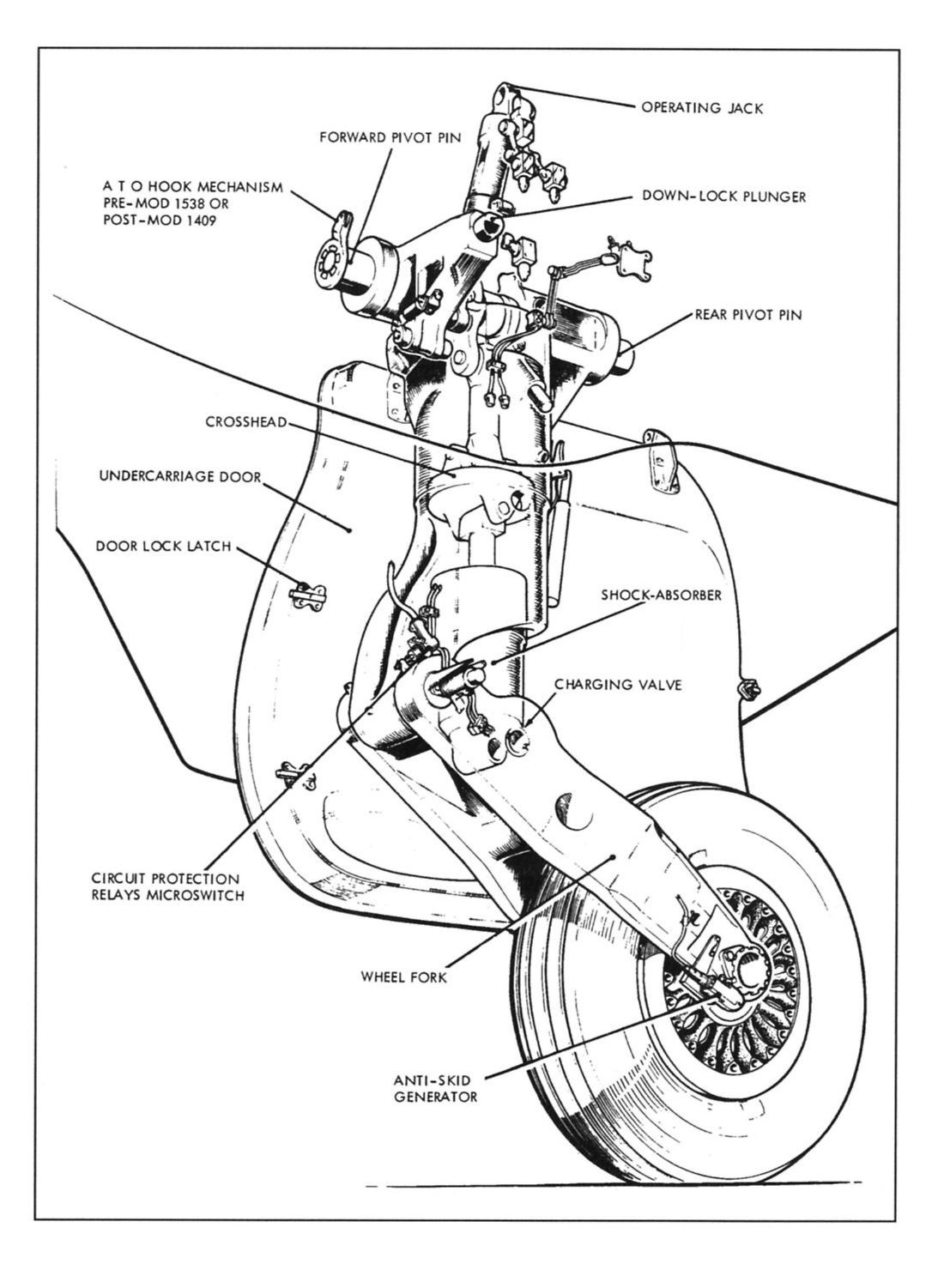
One of the big challenges on the Buccaneer is the main landing gear. It is famous for a massive landing gear, designed for carrier landings, but the challenge is getting it to fit in the small (scale) bay. The full-scale utilized a shortening mechanism that pulled up the trailing link and shock-strut as the gear retracted, tucking the wheel up close the main leg. The retract angle is also only about 65degrees, so a custom gear set would be required - nothing off the shelf was going to work. The nose gear retract could use a standard 90deg unit, but with a custom strut.
Having used both air and electric retracts and brakes on my previous models, I made the decision that I would try to use components from the Electron Retracts range as these have been bullet-proof on my Ultra Flash. After e-mailing Gaspar (of Xicoy ECU fame) at Electron I ordered a pair of their largest retract motors, threaded drive rods and pull-up bars, along with a controller, 90deg nose gear retract and 5" diameter wheels and electric brakes, all on the understanding that they may not work as they designed in my custom application.
I took a fuselage cross section at the retract position to define a working volume and set about trying to come up with a solution. Multiple attempts kept leading to a dead-end.
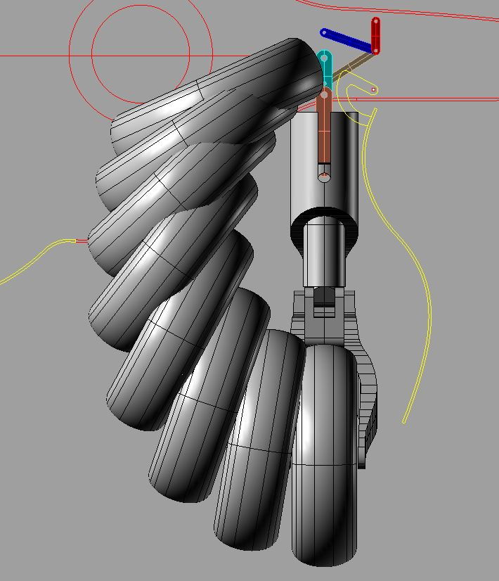
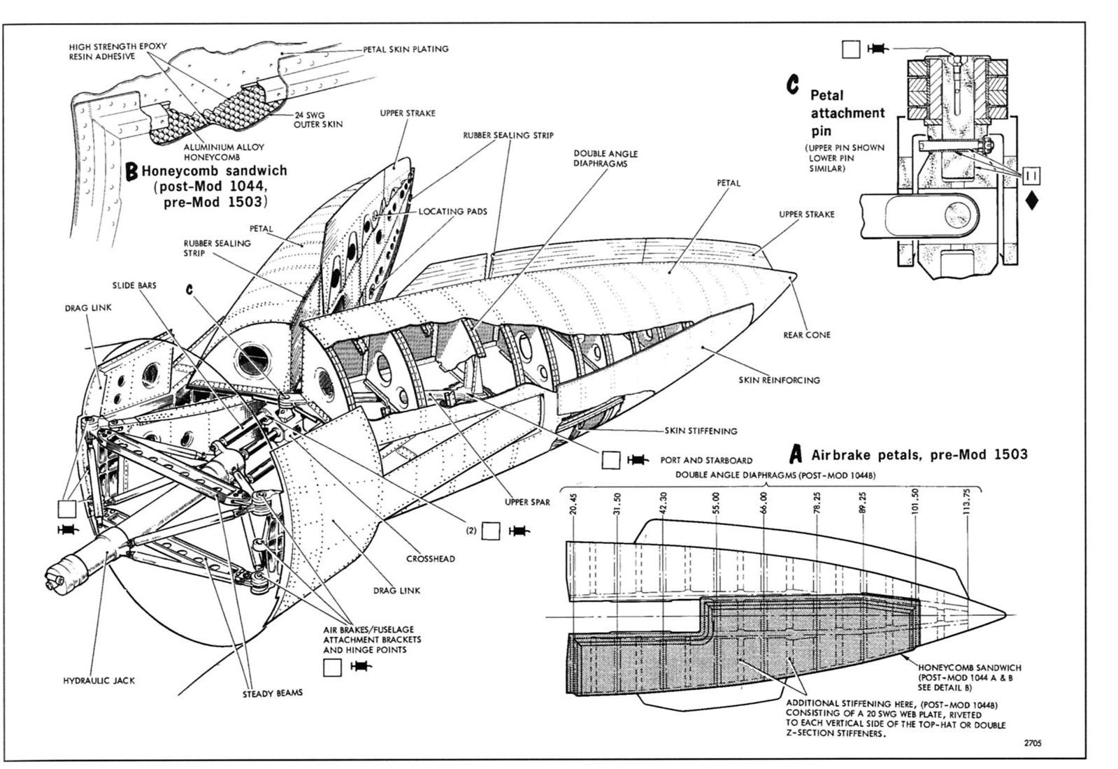
After about 6 months of trying, I eventually managed to get a copy of the section out of the servicing manual which described how the full-scale shortening mechanism actually worked, along with some drawings - this was the key. I reproduced the intent of the mechanism and started to see a solution come to life. After multiple iterations I found a linkage geometry that achieved what I needed, all the while keeping the full-scale pivot point location and scale geometry of the leg and fitting in the scale outline of the wheel well.
At each iteration, a sweep of the wheel during the retract stroke was needed, as a lot of the initial solutions resulting in the wheel not clearing the door cut-out.
Initial solution shown below.
Having used both air and electric retracts and brakes on my previous models, I made the decision that I would try to use components from the Electron Retracts range as these have been bullet-proof on my Ultra Flash. After e-mailing Gaspar (of Xicoy ECU fame) at Electron I ordered a pair of their largest retract motors, threaded drive rods and pull-up bars, along with a controller, 90deg nose gear retract and 5" diameter wheels and electric brakes, all on the understanding that they may not work as they designed in my custom application.
I took a fuselage cross section at the retract position to define a working volume and set about trying to come up with a solution. Multiple attempts kept leading to a dead-end.
After about 6 months of trying, I eventually managed to get a copy of the section out of the servicing manual which described how the full-scale shortening mechanism actually worked, along with some drawings - this was the key. I reproduced the intent of the mechanism and started to see a solution come to life. After multiple iterations I found a linkage geometry that achieved what I needed, all the while keeping the full-scale pivot point location and scale geometry of the leg and fitting in the scale outline of the wheel well.
At each iteration, a sweep of the wheel during the retract stroke was needed, as a lot of the initial solutions resulting in the wheel not clearing the door cut-out.
Initial solution shown below.
 10-30-2018, 02:36 PM
#77
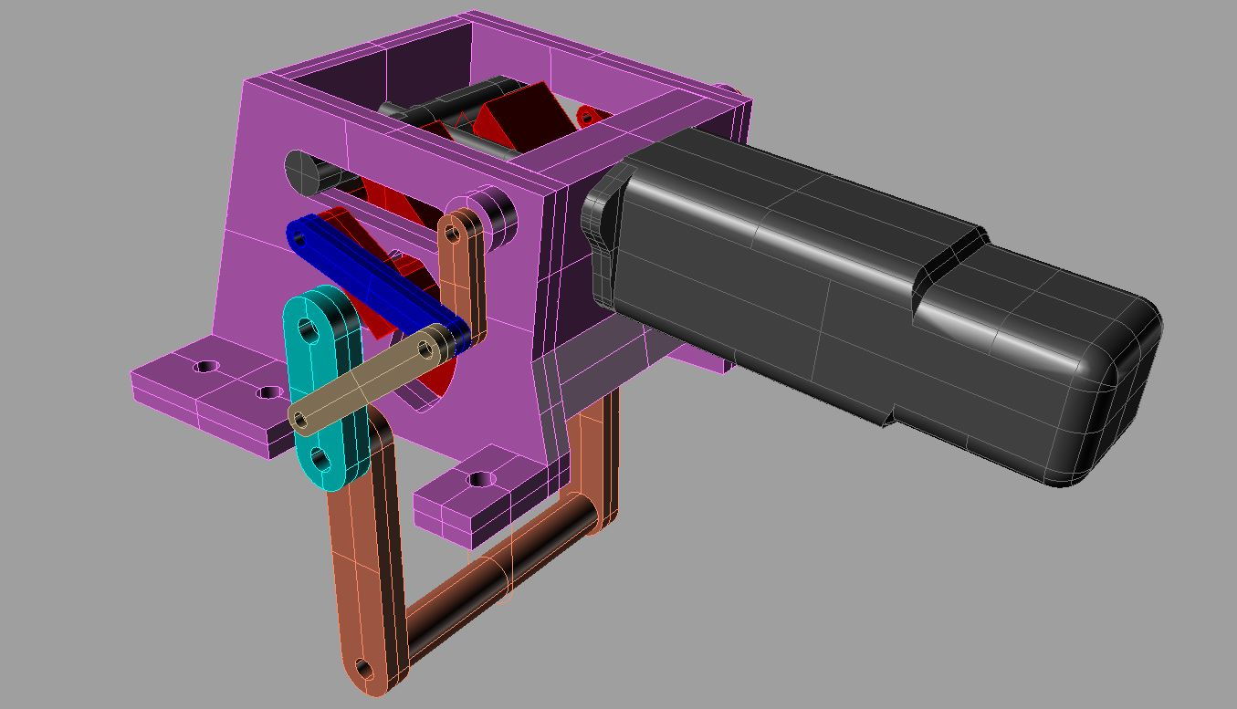
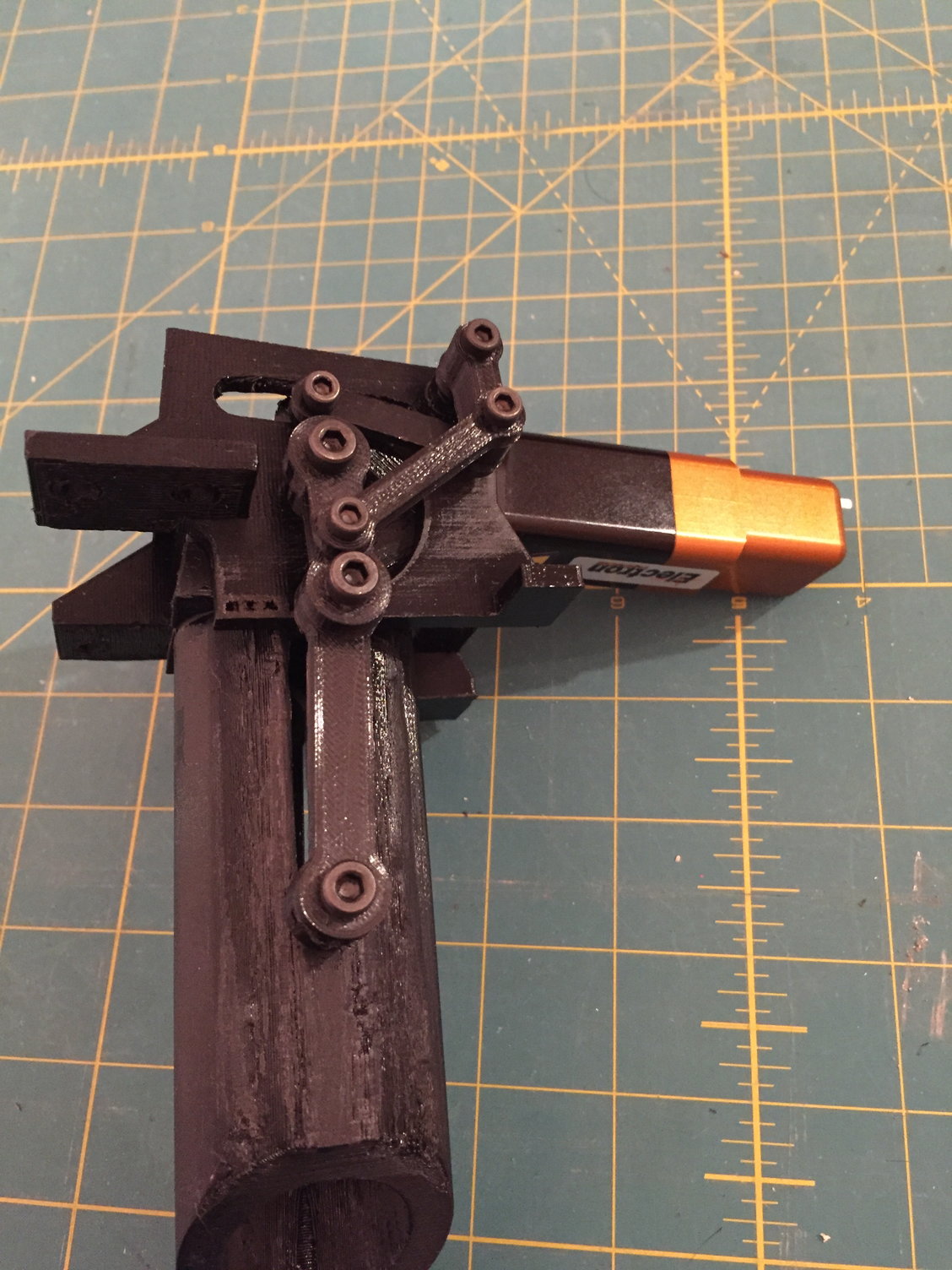
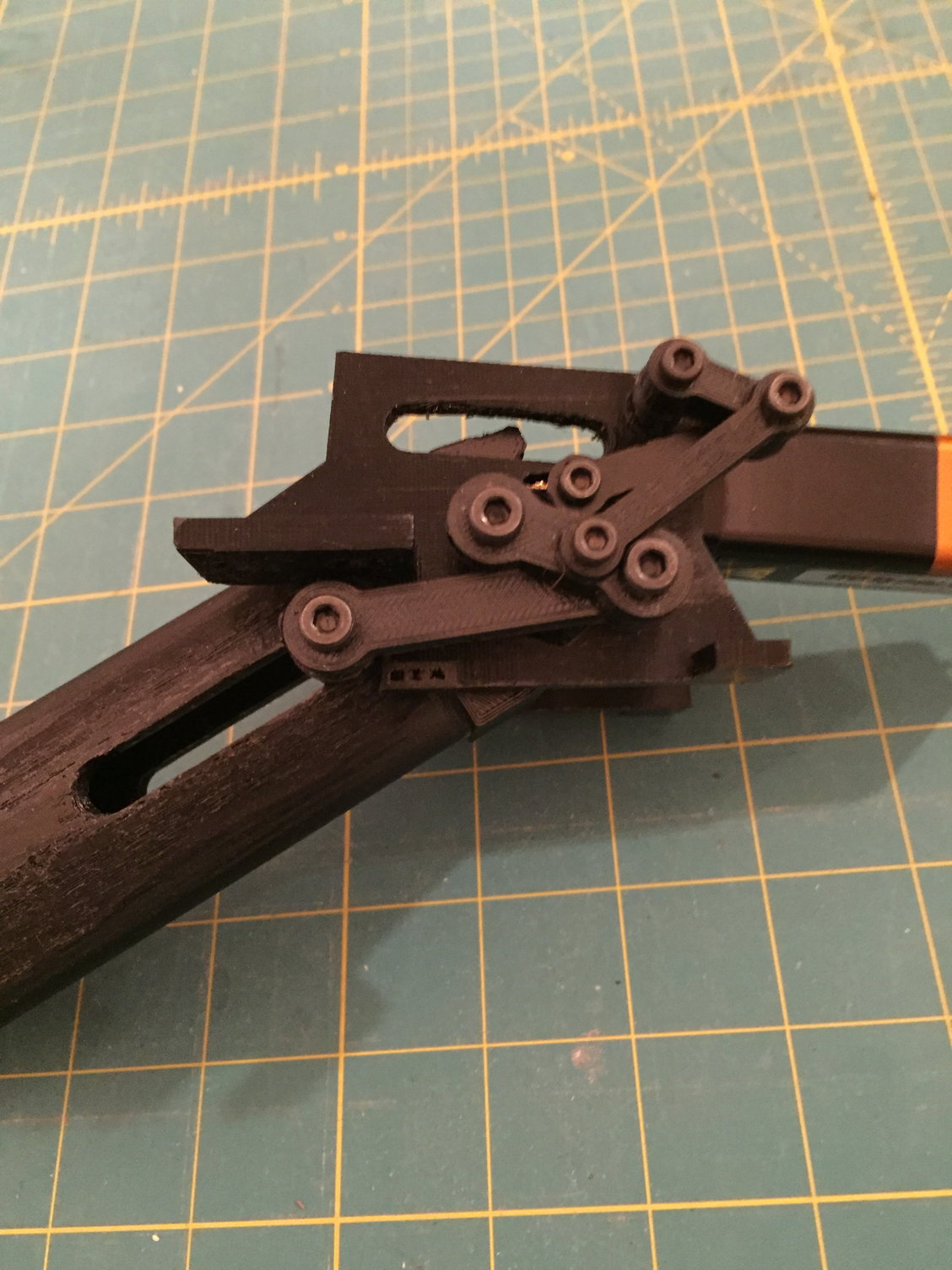
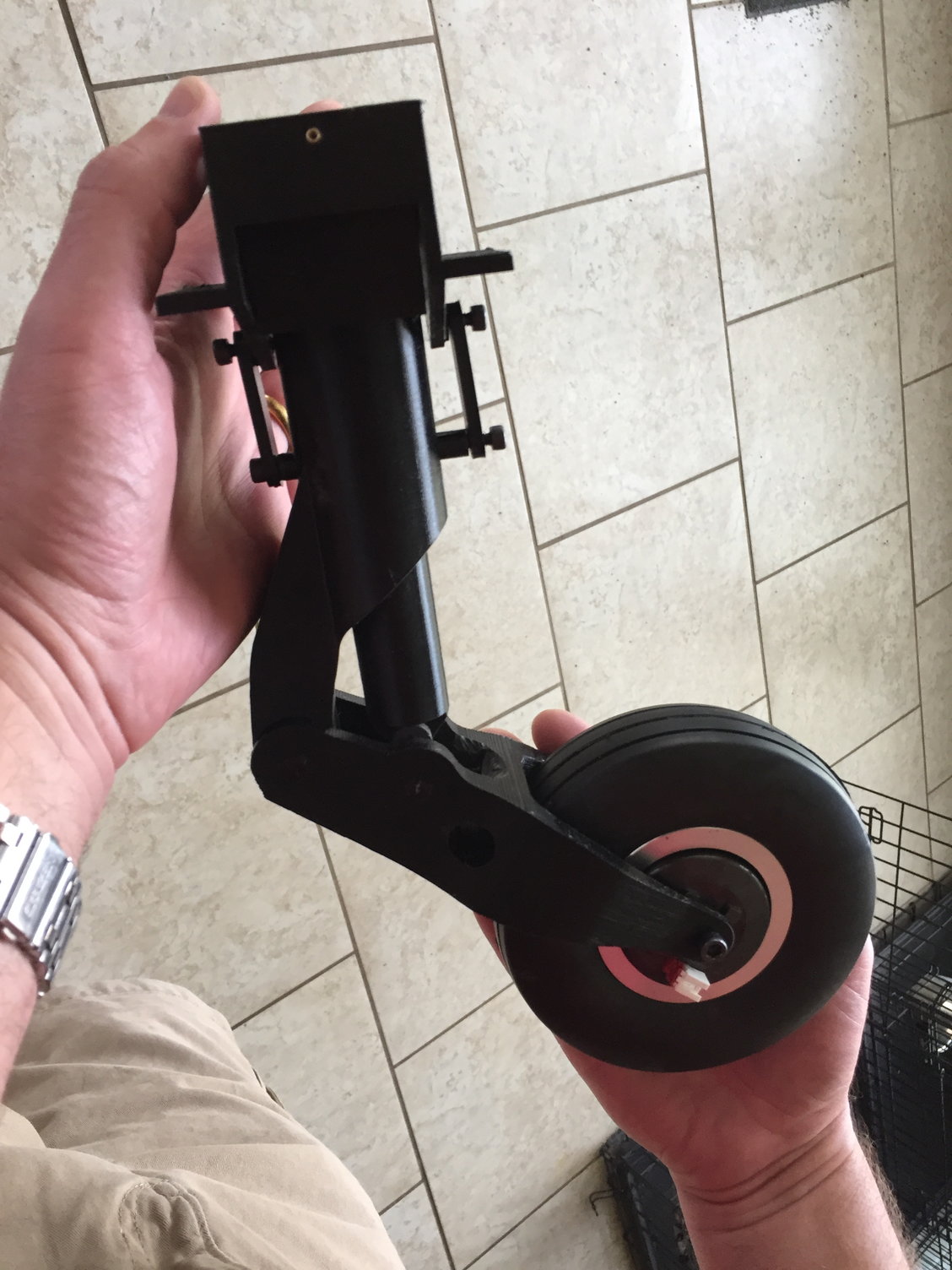
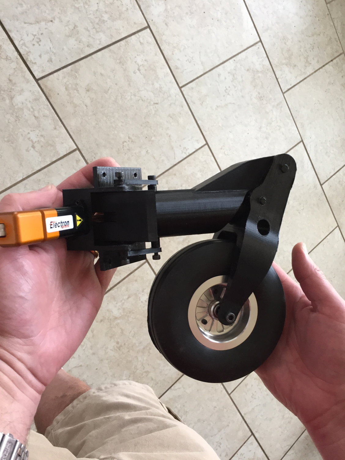
With an initial design laid out in CAD, I then 3D printed a complete retract unit to validate the operation. This was extremely helpful as it identified a number of issues that had to be resolved. After a couple of iterations, I ended up with a solution that I am completely happy with. Building the shock-strut part remains a risk that I need to work through.
There is basically a linkage that acts on a pull-up bar that slides the shock-strut up into the main-leg during the retract cycle. When down, all the load-bearing parts are aligned so that virtually no load is transferred into the shortening mechanism.
Now to try to get the retracts made in metal.
I have had some initial discussions with Darrel at Sierra Giant Scale, who made new retract units for my Hunter. It seems feasible, so I am now converting my CAD model into engineering drawings as he uses 2D CAD and had trouble importing the files I sent him of my Hunter design. I also got a couple of quotes from e-machineshop.com which were helpful, but I would probably need to rework my design with the correct tolerances if I went that route.

 10-31-2018, 03:10 AM
#81
I made the decision I was going to do the Buccaneer a year ago, in November 2017 and I started making my first part (the fin cap) in December 2017, so its been basically 1 year so far.
Great timing of the question as I have now brought this thread up to date with current progress, and future posts will be in 'real-time' as I progress the build.
Thanks to all for following and the supportive comments.
Paul
Great timing of the question as I have now brought this thread up to date with current progress, and future posts will be in 'real-time' as I progress the build.
Thanks to all for following and the supportive comments.
Paul
10-31-2018, 04:50 AM
#82

Join Date: Sep 2013
Posts: 631
Likes: 0
Received 0 Likes
on
0 Posts
I made the decision I was going to do the Buccaneer a year ago, in November 2017 and I started making my first part (the fin cap) in December 2017, so its been basically 1 year so far.
Great timing of the question as I have now brought this thread up to date with current progress, and future posts will be in 'real-time' as I progress the build.
Thanks to all for following and the supportive comments.
Paul
Great timing of the question as I have now brought this thread up to date with current progress, and future posts will be in 'real-time' as I progress the build.
Thanks to all for following and the supportive comments.
Paul
Wow, very nice project! Perfect Work👌👌👌👌👌😍
 10-31-2018, 11:33 AM
#85
I don't think a 3d printed (or plastic in general) landing gear would be strong enough. Maybe for a static model, but not for flying or with something approaching 50lb. Also, I only have a generic representation of the shock strut, not a functional part, so the gear has no 'give' to it.
Paul
Paul
10-31-2018, 02:19 PM
#88

Genius Level Modelling!
Obviously this thread belies the amount of work you have put into this. Thanks for taking the time to share this with us.
And the Blackburn Buccaneer is a great subject. Aircraft of this era seem to have more personality.
Obviously this thread belies the amount of work you have put into this. Thanks for taking the time to share this with us.
And the Blackburn Buccaneer is a great subject. Aircraft of this era seem to have more personality.
10-31-2018, 03:23 PM
#89
Roger,
Many thanks - your comments are humbly received.
I'm just having fun and trying new things - I watch with awe at what some of the craftsmen on here, such as Mugu, Invertmast, Ron S (with his secret project ) and over at rcscalebuilder.com can produce and I'm trying my best to produce something that looks reasonable.
But, having fun is the main thing - I'm just glad other folks are getting some pleasure from what I am doing.
Regards,
Paul
Many thanks - your comments are humbly received.
I'm just having fun and trying new things - I watch with awe at what some of the craftsmen on here, such as Mugu, Invertmast, Ron S (with his secret project
) and over at rcscalebuilder.com can produce and I'm trying my best to produce something that looks reasonable.But, having fun is the main thing - I'm just glad other folks are getting some pleasure from what I am doing.
Regards,
Paul
 11-06-2018, 04:44 AM
#91
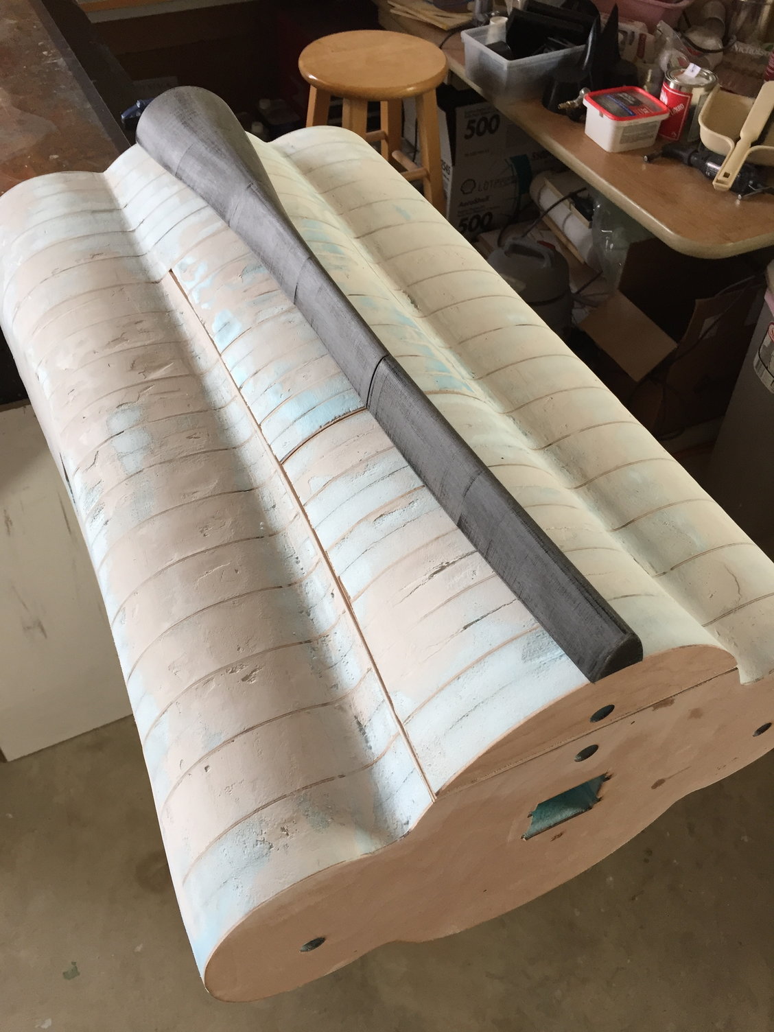
I've been working on the fuselage plug. After completing the rough sanding of the foam, I applied the initial filler (Spackle), sanded it down, and then applied the first layer of 9oz glass cloth to the rear fuselage section and the two hatches. Working on the body filler (Icing) to develop the final shape of the rear fuselage. Once the filling is complete, I'll add a second layer of glass prior to priming and surface coat.
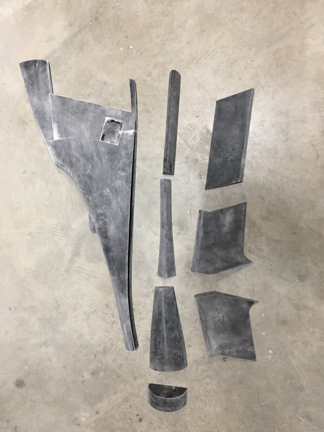
My 3D printer has been busy also, and I have completed printing the entire spine and fin. Printed in 9 sections over about 5 days, it is over 5 feet in length. CA'd together into the individual sections, I've started to glass them to provide a consistent surface prior to priming and surface coating, which will wait until they have been glued onto the fuselage plug.
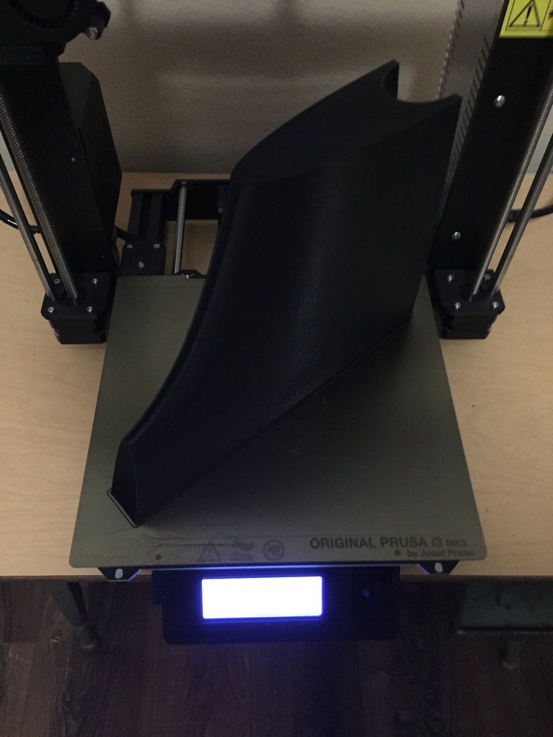
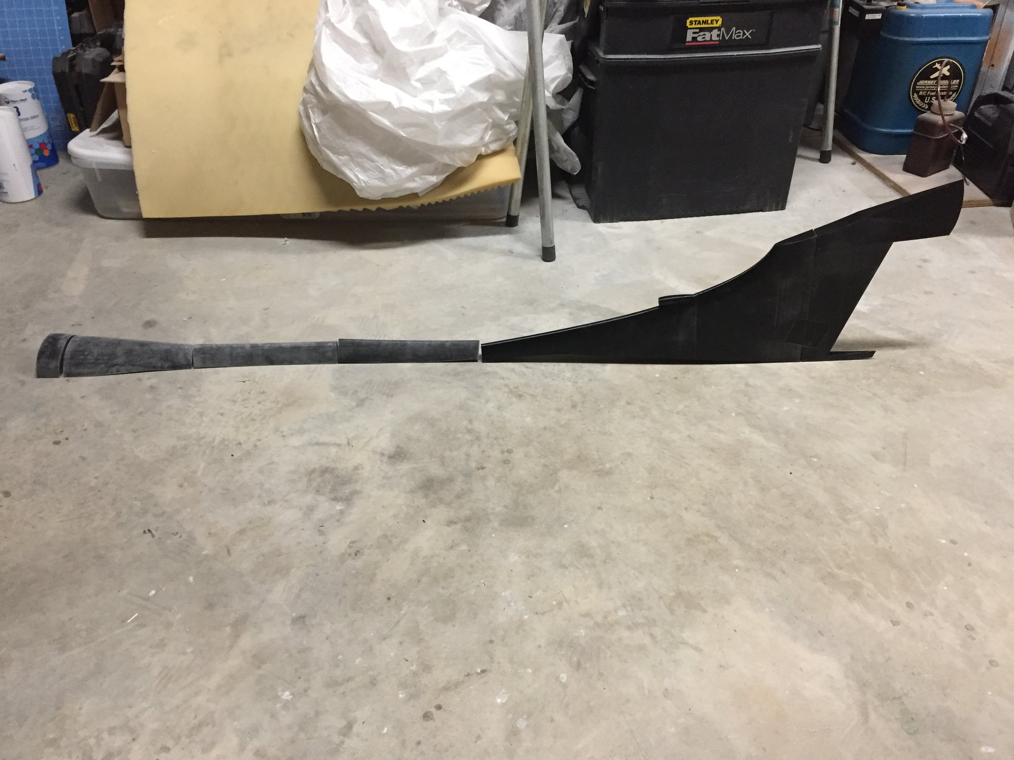
My 3D printer has been busy also, and I have completed printing the entire spine and fin. Printed in 9 sections over about 5 days, it is over 5 feet in length. CA'd together into the individual sections, I've started to glass them to provide a consistent surface prior to priming and surface coating, which will wait until they have been glued onto the fuselage plug.
Last edited by JSF-TC; 11-06-2018 at 04:52 AM.
11-06-2018, 06:02 AM
#92
My Feedback: (20)
Wow Paul, absolutely amazing. I the technology is now available to us regular modelers to achieve almost any shape and size you can think of (if you can learn to use it). I love watching your progress. Its inspiring!
Thanks,
Gary
Thanks,
Gary
11-06-2018, 06:44 AM
#93
Once again, fantastic work. Can't wait to see this thing up close one day at a meet.
11-06-2018, 06:53 AM
#94
Thanks.
The cloth is just laid down and stippled through with a 1" brush. The cloth I have been using is a satin weave which conforms to compound curves really well. It is really soft and has a fine weave. Much finer than some regular plain weave 6oz cloth that I have also used.
https://www.fibreglast.com/product/S...erglass_Fabric
Paul
11-13-2018, 07:28 PM
#96
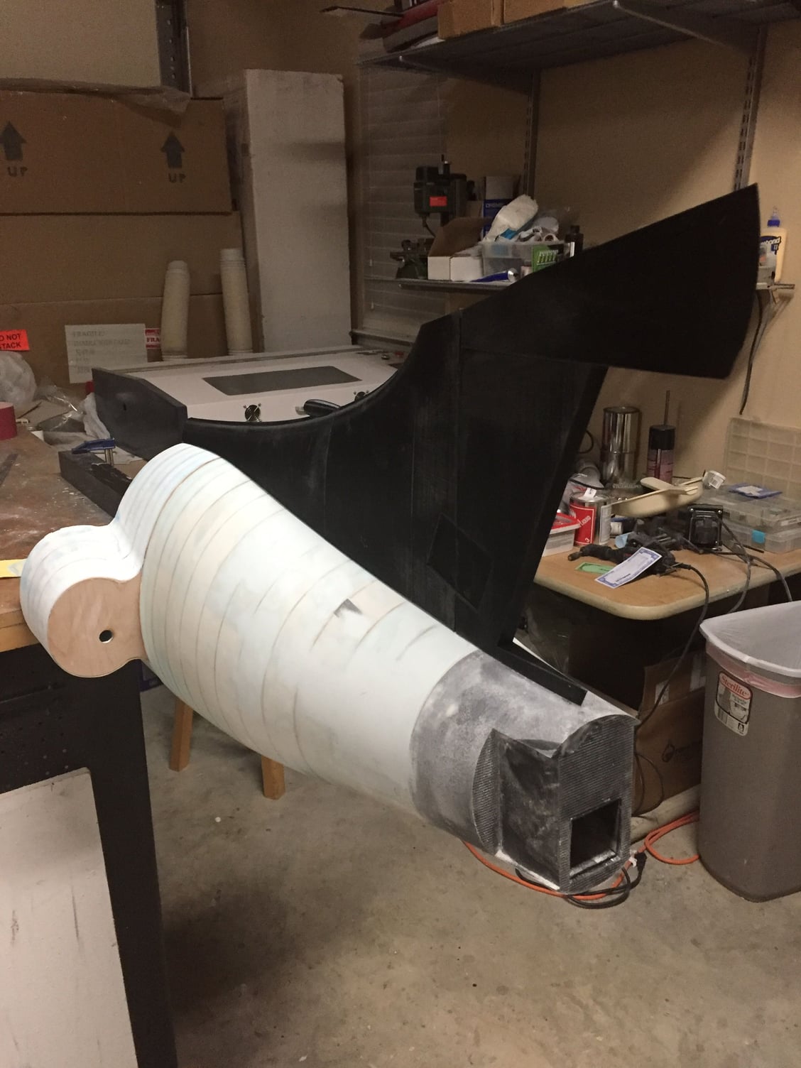
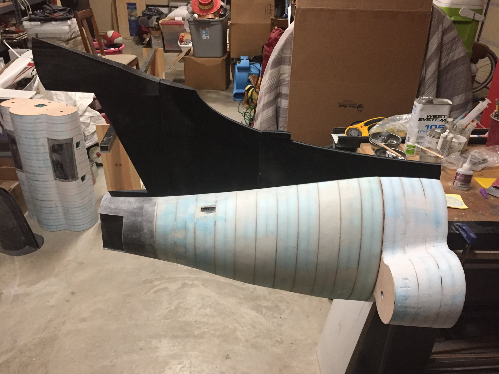
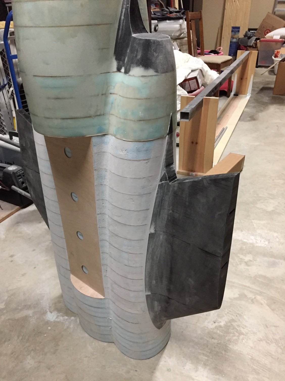
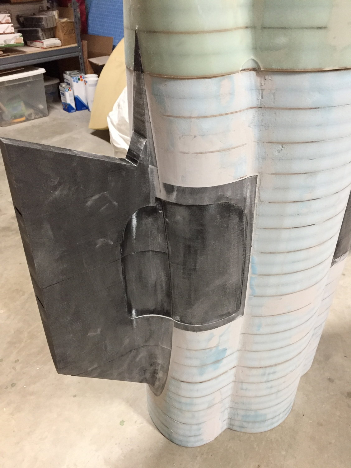
Making steady progress. Bonded the 3D printed inner wings to the center fuselage plug and blended them in. The approach worked well with minimal filler required to get the smooth transition from the nacelle to the wing. Very happy with the result. Center fuselage plug is now ready for its first layer of glass cloth.
Each inner wing was made in 5 pieces and each one took 85hrs total print time and almost an entire 1kg spool of filament each.
All the other 3d printed parts (spine, fin, inner flaps and rudder) have been covered in glass cloth ready for priming.
Paul
Each inner wing was made in 5 pieces and each one took 85hrs total print time and almost an entire 1kg spool of filament each.
All the other 3d printed parts (spine, fin, inner flaps and rudder) have been covered in glass cloth ready for priming.
Paul
Last edited by JSF-TC; 11-13-2018 at 07:37 PM.
11-13-2018, 07:35 PM
#97
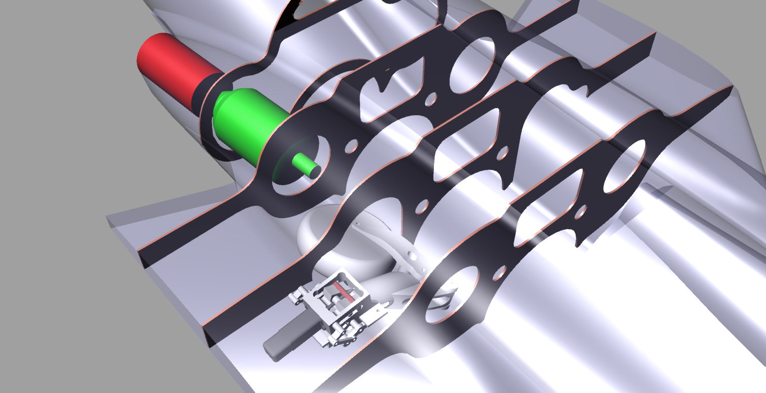
Started to layout the fuselage internal structure.
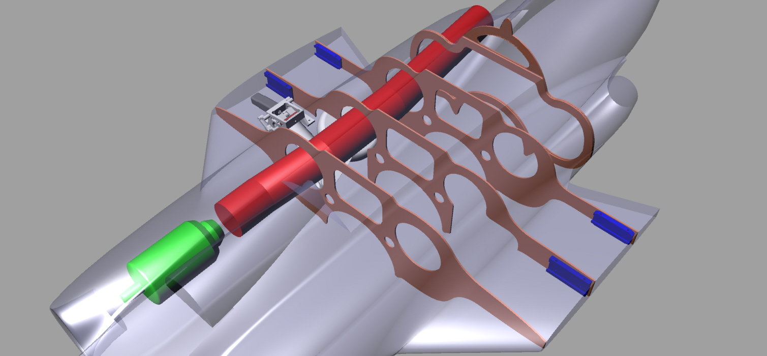
My initial approach was to mount the motors in a nominally scale location, forward of the main landing gear, and have a long pipe. I needed a bent pipe to clear the main gear and to provide the 5deg outward cant of the exhaust duct. The main frame which carries the forward wing joiner has the bottom part cut away to clear the main gear, which is a poor structural arrangement. I was not happy with the integrity of this overall layout.
I then moved the motors back to behind the main gear and this solved 2 problems - a much shorter, straight pipe (around 6" compared to over 30") and a better structural layout of the main frame as I could get a deeper cross section in the frame.
Paul
11-13-2018, 09:45 PM
#98
Join Date: Sep 2013
Posts: 631
Likes: 0
Received 0 Likes
on
0 Posts
Started to layout the fuselage internal structure.
My initial approach was to mount the motors in a nominally scale location, forward of the main landing gear, and have a long pipe. I needed a bent pipe to clear the main gear and to provide the 5deg outward cant of the exhaust duct. The main frame which carries the forward wing joiner has the bottom part cut away to clear the main gear, which is a poor structural arrangement. I was not happy with the integrity of this overall layout.
I then moved the motors back to behind the main gear and this solved 2 problems - a much shorter, straight pipe (around 6" compared to over 30") and a better structural layout of the main frame as I could get a deeper cross section in the frame.
Paul
11-14-2018, 04:11 AM
#99
Mugu,
Agreed, I need to look more seriously at that approach, but I believe that I may have enough room to move the engine back further and dispense with the pipe entirely. Would probably need something to line the exhaust to protect the fuselage - the exit diameter is only 76mm. Gaspar recommends a minimum pipe diameter of 68mm for his M100.
Paul
