


1/7 Scale Blackburn Buccaneer All Composite Scratch Build

 11-18-2018, 05:15 PM
#102

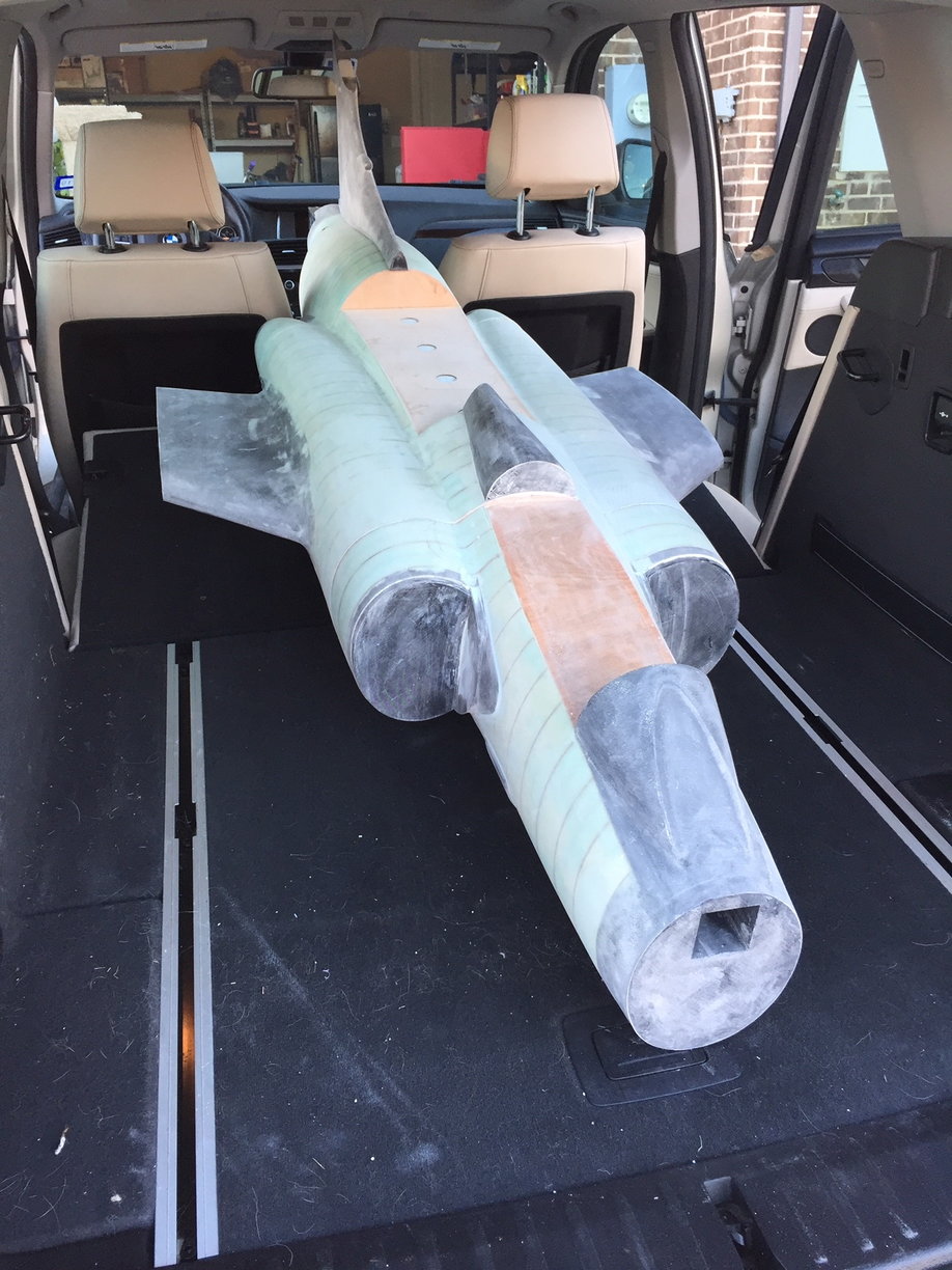
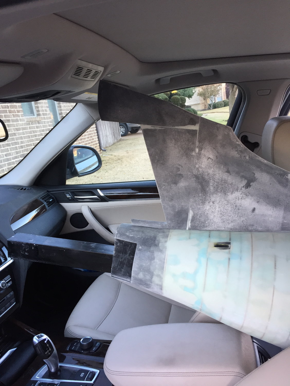
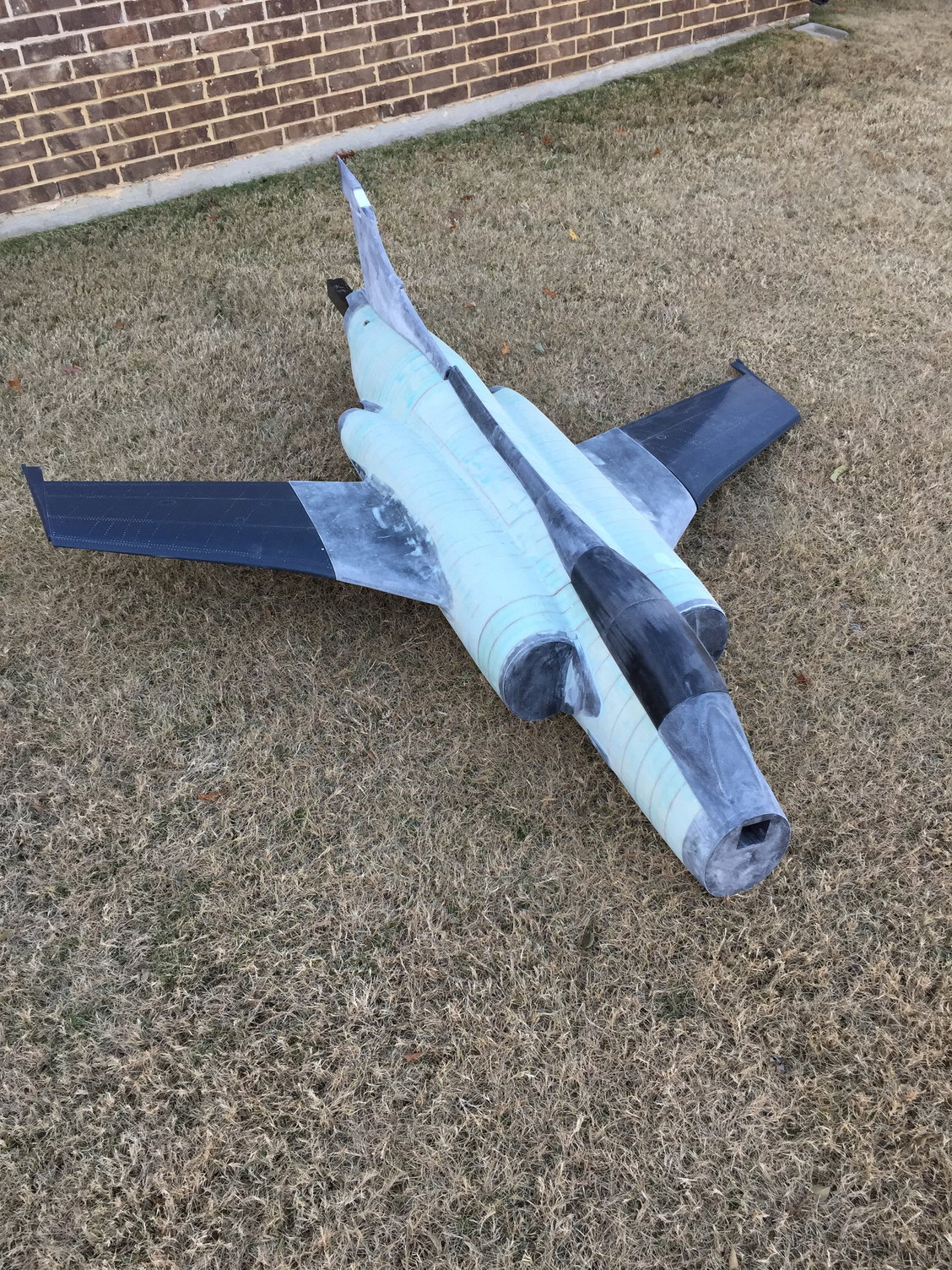
First time the entire fuselage plug has been assembled. The sheer bulk of it is somewhat daunting. It's going to be a Monster!
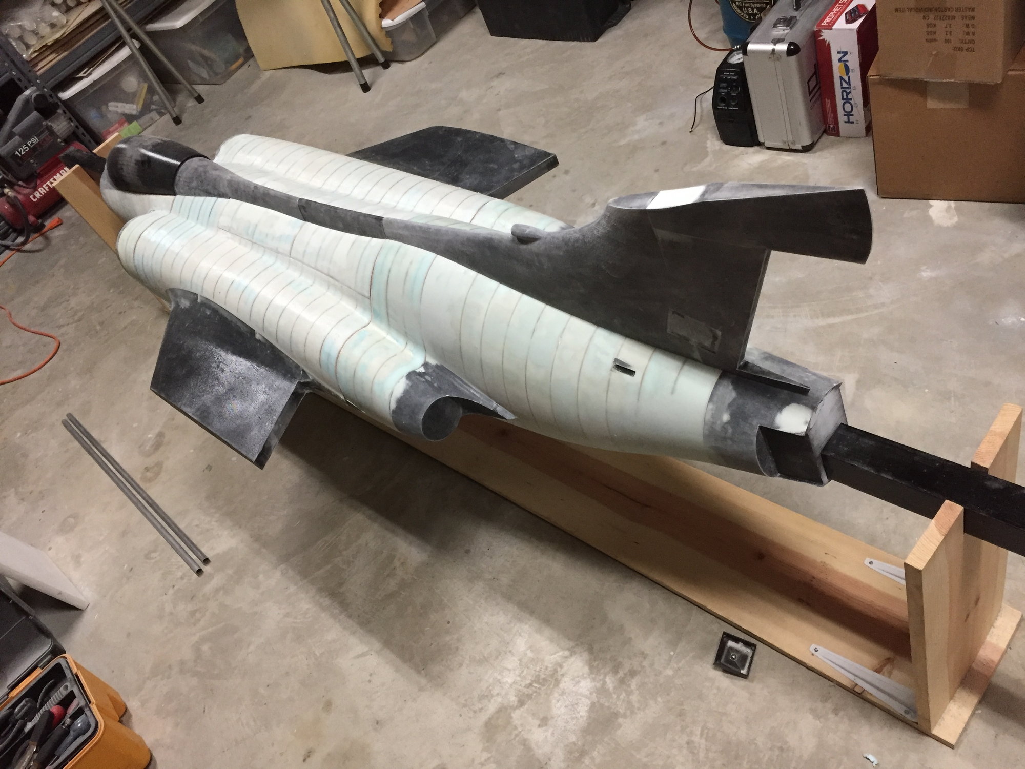
Forward and rear sections have been glassed, filled and re-glassed. Center section has had the initial glass layer applied, ready for sanding, filling and re-glassing. Once all sections have been double glassed I will epoxy on the fin and spine sections before adding primer and surface coat.
Paul
Forward and rear sections have been glassed, filled and re-glassed. Center section has had the initial glass layer applied, ready for sanding, filling and re-glassing. Once all sections have been double glassed I will epoxy on the fin and spine sections before adding primer and surface coat.
Paul
 11-18-2018, 07:42 PM
#103

Great thread Paul. I have 2 questions:
1.) Do the large plastic parts warp much after you print them?
2.) During shaping, did you have any problem with the ply formers "showing through" due to the different properties of the wood and the foam)... the starving horse look.
Bonus question: did you think about printing the whole plug?
I am enjoying this thread thanks for taking the time to post, I know it takes time.
11-19-2018, 04:14 AM
#104
Hi Matt,
Thanks. Glad you are enjoying it.
For warping of the 3d printed parts, initially I was printing with ABS which did suffer from warping and splitting on some of the larger parts. When I bought my own printer I quickly discovered PETG which has all the benefits of ABS but with minimal shrinkage & warping. All the parts I print now are done with PETG. It is a little harder to sand than ABS, but that is about the only downside I see to using it.
Yes, on initial sanding it is easy to get the 'starved horse' effect, but that is where the initial Spackle filler comes in along with filling any damage to the blue foam and hiding any mistakes. The blue foam is surprisingly hard to sand over large areas - the hand-held belt sander was a huge help and I would then finish up with a power orbital sander to help get the final shape. Putting the first layer of glass down gives a good base to use the body filler (I use Icing) to fair over any remaining surface defects and to develop the final shape. I have then been using a final layer of glass to seal everything plus I have heard that climate changes can cause the ply to show through given the different expansion rates of the ply and foam. My 2 layers of glass (both 9oz satin twill weave) are an attempt to mitigate that effect - fingers crossed that it is sufficient.
I did very briefly consider printing the whole plug but not really a practical proposition on my small printer. If I had access to Thomas's (Invertmast) monster printer then I may well have done that. I did ask Oli to quote for his robot machining of the plug, but he never got back to me - a solid wood plug would have probably weighed a ton or more.
Paul

")


 Congrats!
 11-20-2018, 04:50 PM
#109
Oh yes, it had a weapon bay which rotated. Begging to be done on the model.
Have been laying out the lines for it recently.

Considering making it the main fuel tank, just like the full-size. Total volume of the weapon bay is 250oz, so more than enough for 2 100-sized motors.
Paul
Have been laying out the lines for it recently.
Considering making it the main fuel tank, just like the full-size. Total volume of the weapon bay is 250oz, so more than enough for 2 100-sized motors.
Paul
Last edited by JSF-TC; 11-20-2018 at 04:53 PM.
11-21-2018, 12:40 PM
#111
Dave,
Was thinking about that - I would probably lay up a layer or 2 of kevlar for abrasion resistance for the lower skin. If I do make it into a tank I think I will go for a partial capacity in the door and then use a traditional tank in the fuselage prior to the air trap. Maybe around 120oz in the door and the same again in the fuselage.
Paul
 11-22-2018, 08:59 AM
#113
Thomas,
Thanks for the comments.
I agree, I would never have contemplated taking this on without CAD, laser cutting and 3D printing. There is no way my hand-skills are good enough to manually cut out 40+ ply bulkheads accurately or get all those complex curves flowing correctly, let alone manually drawing out the correct lines to start with.
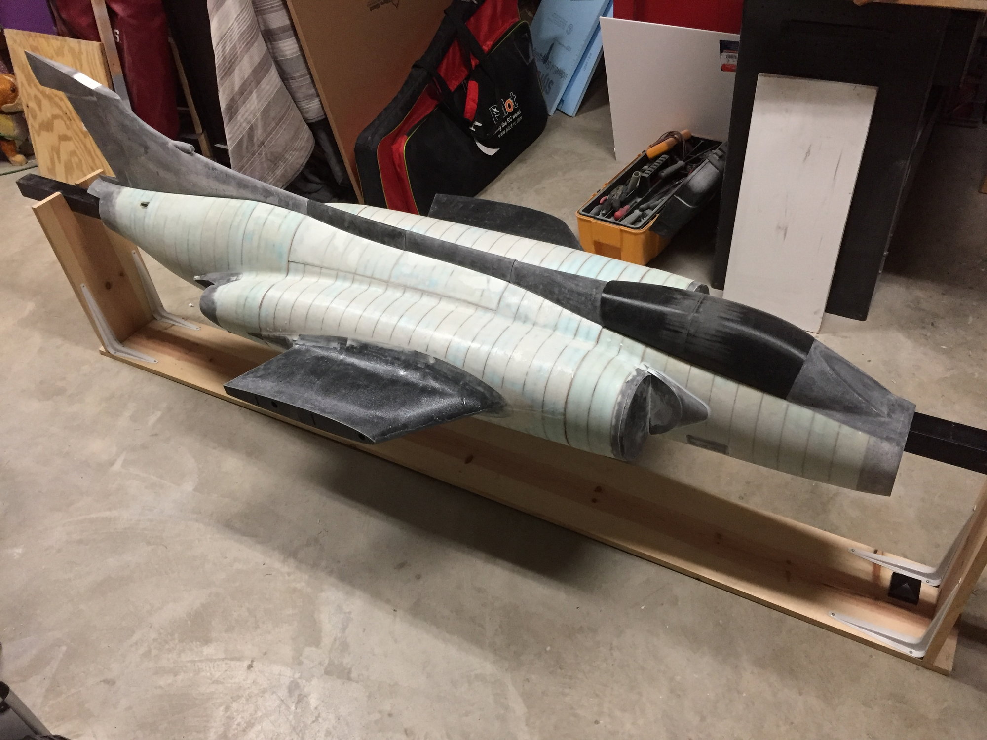
Center fuselage plug has now been double glassed and is curing. Time for some more CAD work.
Paul
Thanks for the comments.
I agree, I would never have contemplated taking this on without CAD, laser cutting and 3D printing. There is no way my hand-skills are good enough to manually cut out 40+ ply bulkheads accurately or get all those complex curves flowing correctly, let alone manually drawing out the correct lines to start with.
Center fuselage plug has now been double glassed and is curing. Time for some more CAD work.
Paul
 11-23-2018, 09:54 PM
#116


You might want to consider using airex/ carbon fiber internals instead of lightply. Except for the landing gear support structure.
You should still be able to use your laser cutter for this material, cutting each side up separately. It will just stink a lot more ( make sure you exhaust the fumes from any enclosed area ).
11-24-2018, 06:57 AM
#117

Join Date: Sep 2013
Posts: 631
Likes: 0
Received 0 Likes
on
0 Posts
 11-24-2018, 09:23 PM
#120
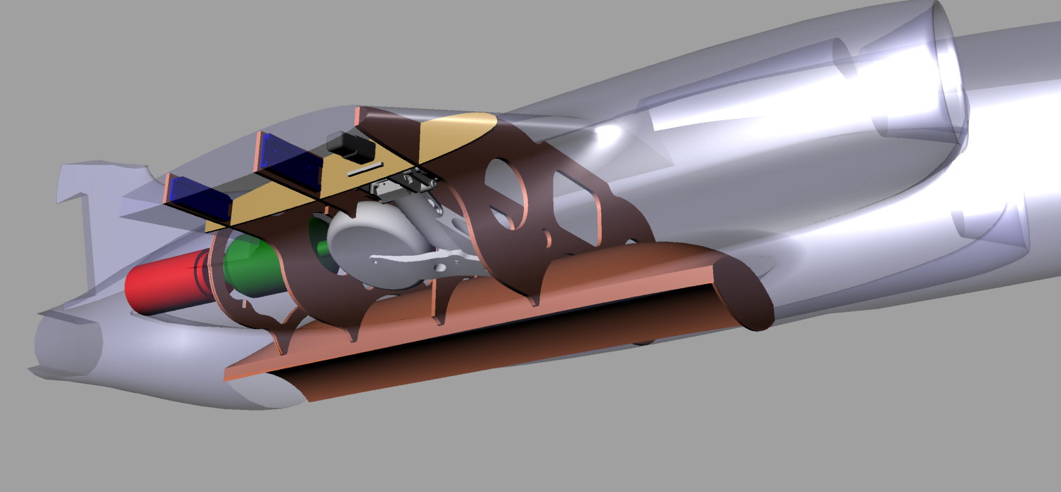
Contemplating a single engine install design, as I have concerns that a twin install with the engines mounted to the rear will result in a very tail-heavy model.
Mocked up a Jetcat 220RXi and laid out a Y pipe. Would have to be installed from the rear of the center fuselage prior to attaching the rear section.
Its a very severe Y pipe as the outlet centers are 15" apart with an overall length of 20", so the split angle is around 40 degrees per side.
Will have to lay out an S-duct to direct the inlet air towards the engine.
11-25-2018, 01:01 AM
#121
Personally I’d stick with a twin. The noise of the Y pipe set ups can be unpleasant, then there is the amount of work you have done, two independent turbines would give you a better chance if you ever get a flame out, as rare as they are. Have you done any calculations of the two options? Weight of the big Y pipe, the heat protection heeded and turbine verses two small pipes and two smaller turbines. That’s a long nose to get the equipment way forward of the balance.
Dave
Dave
11-25-2018, 11:59 AM
#122
My Feedback: (1)
Personally I�d stick with a twin. The noise of the Y pipe set ups can be unpleasant, then there is the amount of work you have done, two independent turbines would give you a better chance if you ever get a flame out, as rare as they are. Have you done any calculations of the two options? Weight of the big Y pipe, the heat protection heeded and turbine verses two small pipes and two smaller turbines. That�s a long nose to get the equipment way forward of the balance.
Dave
Dave
I was a little sceptical when we discussed the single engine idea yesterday, but after seeing your depiction of it above I am going to have to agree with Dave. I believe if you used a pipe with that wide of a Y it is going to cause way more problems than it solves. F-18 and F-4 style Y pipes are relatively in-efficient, but I think something like you are proposing will probably net you only about 50% of the turbine's available thrust, not to mention the heat issues at the center of the pipe.
If I were you, I would shoot for building the aft section of the fuselage as light as possible, use twin turbines placed as far forward as you reasonably can, and then get creative with the design of the ducting.

If you need any help, or just need to do some brainstorming I would love to help.
11-25-2018, 06:33 PM
#123
Dave/ Kevin,
Many thanks for the feedback. I was skeptical too, but I had to do the option justice and lay it out. Agree that making such a severe pipe and getting it to work well would be a challenge.
I'm looking again at both the forward and rear mounted twin options, but I think the rear mounted one with the short pipe will work out to be the choice.
One thing with the rear mounted option that I'm concerned about is as the rear fuselage is closed, inlet air at high speed will pressurize the fuselage cavity and have nowhere to go. I think a fully-ducted engine install would alleviate this concern, but a lot more design and build work.
Paul
11-26-2018, 12:32 AM
#124
Paul
Fully ducted is always best, but I would not be concerned about the air pressure. When you are going full beans the turbines will be sucking up plenty of air and even throttling back while travelling with energy the throughput will be through and around the turbines.
Will you have the AB doors functional at the back? If so the various gaps and openings will reduce any pressure in there.
Dave
11-26-2018, 04:10 AM
#125
Dave,
Yes, the plan is to have a functional speedbrake (next on the design list), so yes, there should be some air paths around that area.
Due to the small size of the scale engine exhaust nozzle openings, they are only 76mm in diameter. Gaspar recommends no less than a 68mm diameter pipe for his Jets Munts Merlin 100XBL, so that only leaves a 4mm wide annulus for the outer pipe. No wide air gap around the outer pipe to help with fuselage venting unfortunately.
The pipe will sit in the fuselage like the Ultra Flash, with the outer pipe wall touching the end of the fuselage opening.
I would leave the arrestor hook recess as an opening initially to get more fuselage pressure relief.
Paul

