


The Skymaster Northrop T-38 Talon Project of 2019


 01-08-2019, 07:45 PM
#52

Thread Starter
One of my goals with building airplanes is to make them stronger and lighter. It is of benefit to have things break predictably as with the BVM models having �flex plates� holding the landing gear so only the plates break on a hard landing. They are easy to replace as well. In all cases a lighter plane is always a better plane. For this T-38 project I am starting with the cockpit.
I will use two astronaut pilots. I removed the plastic legs with boots and will stuff the pants with cotton. You cannot see the feet anyway - they were comparatively very heavy. I saved about 2oz. per pilot this way. I am planning on buying NASA blue colored material and making proper uniforms. In the interest of time I may try to farm out this project though I actually can sew fairly well.
The supplied two seat cockpit tub is made of brittle plastic and thick heavy plywood. It probably weighed at least two pounds. The details were well done and fully included but it fit poorly and needed a lot of �plastic surgery� to make it fit. I chose another route. I am making one from scratch. The plywood instrument panels alone weigh about 3oz. each. Though very nice looking, detailed and 3-dimensional, they are for the military version of the T-38 so I did not use these. That�s another 6 oz. savings. More to come:
01-08-2019, 08:57 PM
#53


One of my goals with building airplanes is to make them stronger and lighter. It is of benefit to have things break predictably as with the BVM models having �flex plates� holding the landing gear so only the plates break on a hard landing. They are easy to replace as well. In all cases a lighter plane is always a better plane. For this T-38 project I am starting with the cockpit.
I will use two astronaut pilots. I removed the plastic legs with boots and will stuff the pants with cotton. You cannot see the feet anyway - they were comparatively very heavy. I saved about 2oz. per pilot this way. I am planning on buying NASA blue colored material and making proper uniforms. In the interest of time I may try to farm out this project though I actually can sew fairly well.
The supplied two seat cockpit tub is made of brittle plastic and thick heavy plywood. It probably weighed at least two pounds. The details were well done and fully included but it fit poorly and needed a lot of �plastic surgery� to make it fit. I chose another route. I am making one from scratch. The plywood instrument panels alone weigh about 3oz. each. Though very nice looking, detailed and 3-dimensional, they are for the military version of the T-38 so I did not use these. That�s another 6 oz. savings. More to come:
01-09-2019, 05:07 AM
#54
Thread Starter
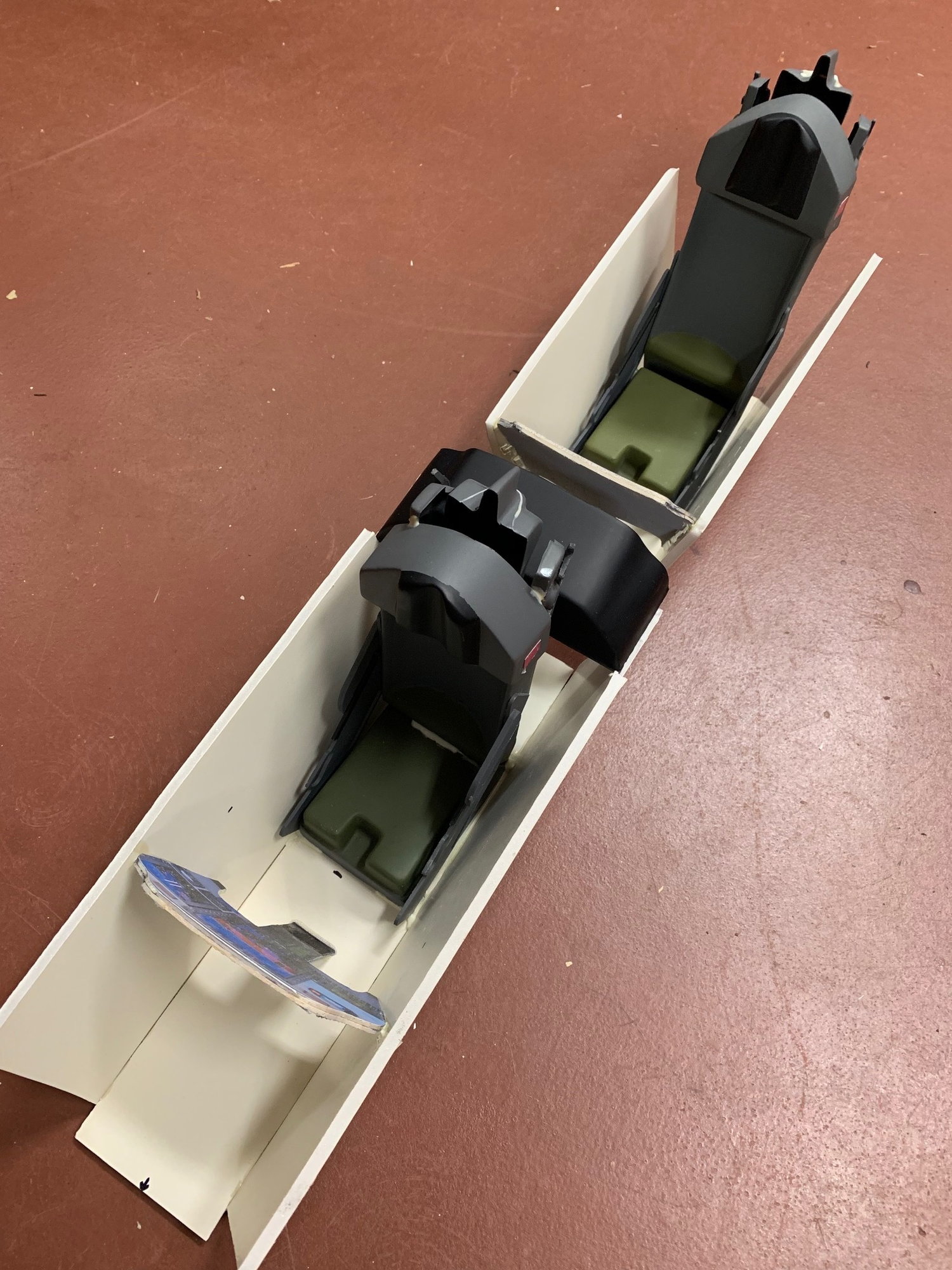
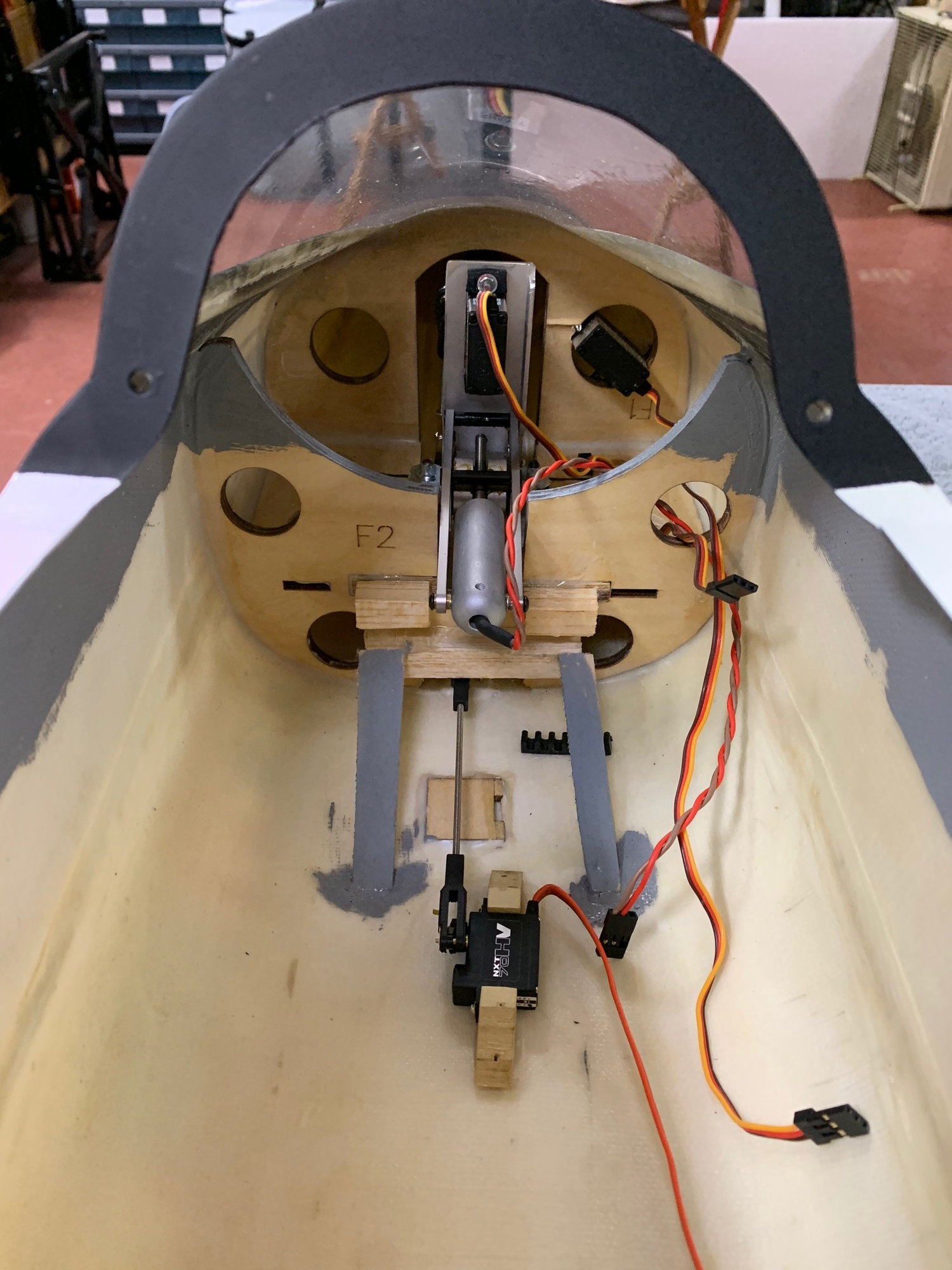
I used thick foam poster board for my tub. It is a two piece tub. The rear one sits a little higher than the foreward tub piece. I used proper NASA instrument panels I printed then glued onto thin balsa wood. The instrument panels are not 3-dimentional but look good enough to me. I then mounted the original supplied side panel instrument boards. These were made of a dense plastic and relatively thick. I used a belt sander and thinned them making them 1/3 as heavy. Another 2oz plus saved here between the four panels. They are also less wide as my cockpit is actually more narrow than the supplied tub. My tub(s) weigh about nothing whereas the supplied tub alone weighed 5oz.
Here are some more pictures of the cockpit:


Last edited by aehaas; 01-09-2019 at 05:11 AM.


 01-09-2019, 11:19 AM
#57
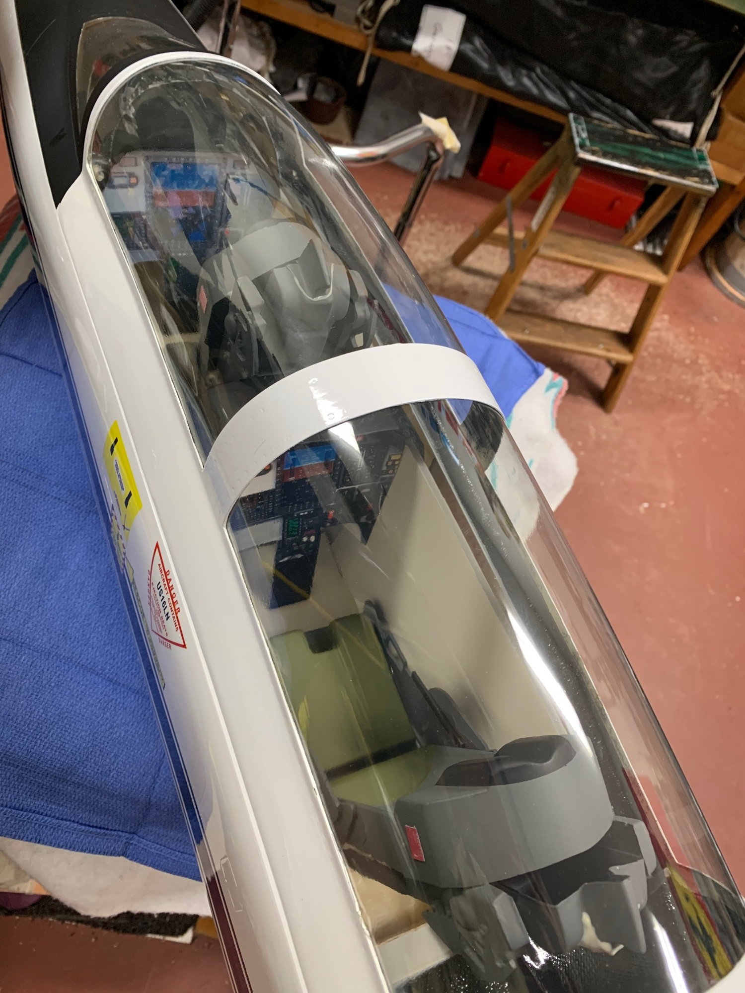
The cockpit looks good. My batteries are all in the very nose as well and the lead I added is in the very nose. I put as much equipment in the nose as I could. I did use an AMT pegasus which is a heavier engine but it sits pretty close to the CG. All of the accessories are ahead of the CG. I would do a quick balance check early before spending too much time trying to save weight that you may end up just adding back to balance it in the end
01-09-2019, 12:50 PM
#58
Thread Starter
I'll be using the new JetCat P130RX that weighs just a little more than the P100. This should save some weight in the back end and I will try to move everything forwards as possible as well.
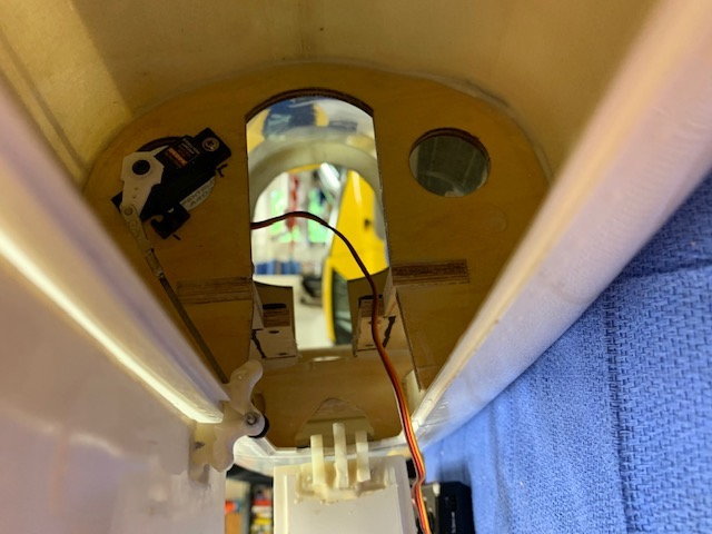
I just installed the nose gear door servo as I am going all electric. It conveniently fit in the existing hole in the first former. I have room for both receiver batteries along the sides of where the retracted nose gear sits. In front of all of this the ECU battery can sit at the tip of the nose cone. I will be fitting a real pitot tube for true airspeed up there as well.
01-16-2019, 10:07 AM
#60
Thread Starter
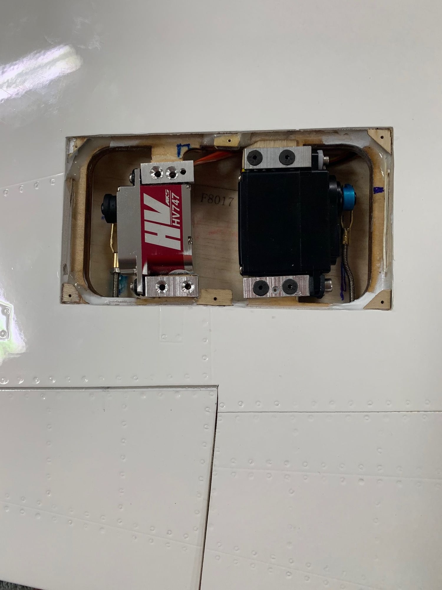
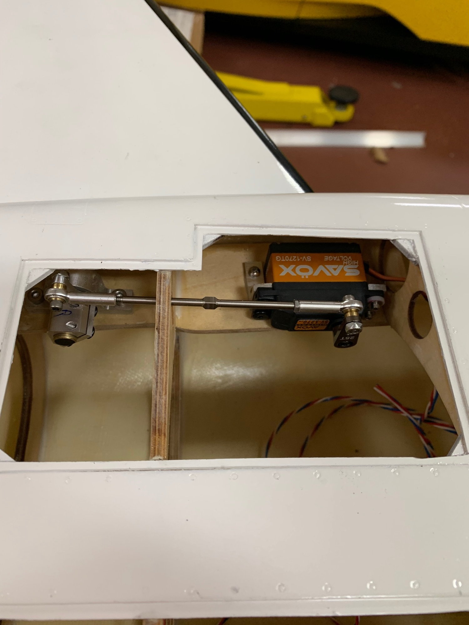
I about finished the servos for the flaps and ailerons. A full sized Hitec servo works the flaps and a mini MKS HV747 works the ailerons. I just have to screw these in but taking a break now. There is a little bit of an optical illusion but they are correct in that the control rods are perpendicular to the hinge lines. The servos have to be twisted some from the "Stock" slots where they are mounted. Easy enough. The mounting wood is a thick plywood and not those smaller, inadequate places shown on the original Plans of the T38-F5-F20 by Skymaster. Actually there are a lot of upgrades compared to these original plans. I mounted the servos as close to the bottom skin of the wing to give me a larger servo arm pointing towards the top wing skin. The horns on the flaps and ailerons are internal. I did the rudder this way as shown on an earlier photo. I always try to do this with my models these days.
The mounting taps for the servo recess cover were either too deep or too shallow requiring shaving or the addition of a sliver of wood. Now the bottom hatch cover is perfectly even with the bottom skin of the wing.
This is no "ordinary" ARF if you are as picky as I am in building models.
The mounting taps for the servo recess cover were either too deep or too shallow requiring shaving or the addition of a sliver of wood. Now the bottom hatch cover is perfectly even with the bottom skin of the wing.
This is no "ordinary" ARF if you are as picky as I am in building models.
 01-16-2019, 03:54 PM
#62
My Feedback: (1)
I about finished the servos for the flaps and ailerons. A full sized Hitec servo works the flaps and a mini MKS HV747 works the ailerons. I just have to screw these in but taking a break now. There is a little bit of an optical illusion but they are correct in that the control rods are perpendicular to the hinge lines. The servos have to be twisted some from the "Stock" slots where they are mounted. Easy enough. The mounting wood is a thick plywood and not those smaller, inadequate places shown on the original Plans of the T38-F5-F20 by Skymaster. Actually there are a lot of upgrades compared to these original plans. I mounted the servos as close to the bottom skin of the wing to give me a larger servo arm pointing towards the top wing skin. The horns on the flaps and ailerons are internal. I did the rudder this way as shown on an earlier photo. I always try to do this with my models these days.
The mounting taps for the servo recess cover were either too deep or too shallow requiring shaving or the addition of a sliver of wood. Now the bottom hatch cover is perfectly even with the bottom skin of the wing.
This is no "ordinary" ARF if you are as picky as I am in building models.
The mounting taps for the servo recess cover were either too deep or too shallow requiring shaving or the addition of a sliver of wood. Now the bottom hatch cover is perfectly even with the bottom skin of the wing.
This is no "ordinary" ARF if you are as picky as I am in building models.
01-16-2019, 04:01 PM
#63
Thread Starter
Have not done throws yet but it will be close to the usual amounts of rotational travel because both the servo arms and horn length are short. It evens out as if they were both long.
01-17-2019, 04:42 AM
#64

I'll be using the new JetCat P130RX that weighs just a little more than the P100. This should save some weight in the back end and I will try to move everything forwards as possible as well.
I just installed the nose gear door servo as I am going all electric. It conveniently fit in the existing hole in the first former. I have room for both receiver batteries along the sides of where the retracted nose gear sits. In front of all of this the ECU battery can sit at the tip of the nose cone. I will be fitting a real pitot tube for true airspeed up there as well.
On the servo to door linkage......break it apart and re-join using semi flexible du-bro pushrod (the yellow one). It could save you the servo in case of a mishap. Just cheap insurance.
love your Talon!
01-17-2019, 05:32 AM
#65
Thread Starter
I'm not worried about the slight curve in the threaded control rod particularly as it only works in compression. There will be no tension/compression cycles. Just the same I will reinforce it, your suggestion is well taken.
Regarding the servo-saver modification, I have tried this in helicopters. They get damaged more often than airplanes. I have tried a myriad of methods and either they do not work as advertised or they fail by themselves. Making the mechanism more complicated adds to the number of possible failure points. I am not against engineered failure points. For example, the BVM flex plates on landing gear work very well.
I keep looking at the mounts of the landing gear in this model as I am hoping to come up with a Flex Plate - like solution. At our relatively short field landing gear damage is the most common issue from short or long landings.
AEHaas


 01-19-2019, 04:45 AM
#67
Thread Starter
Looks very nice !
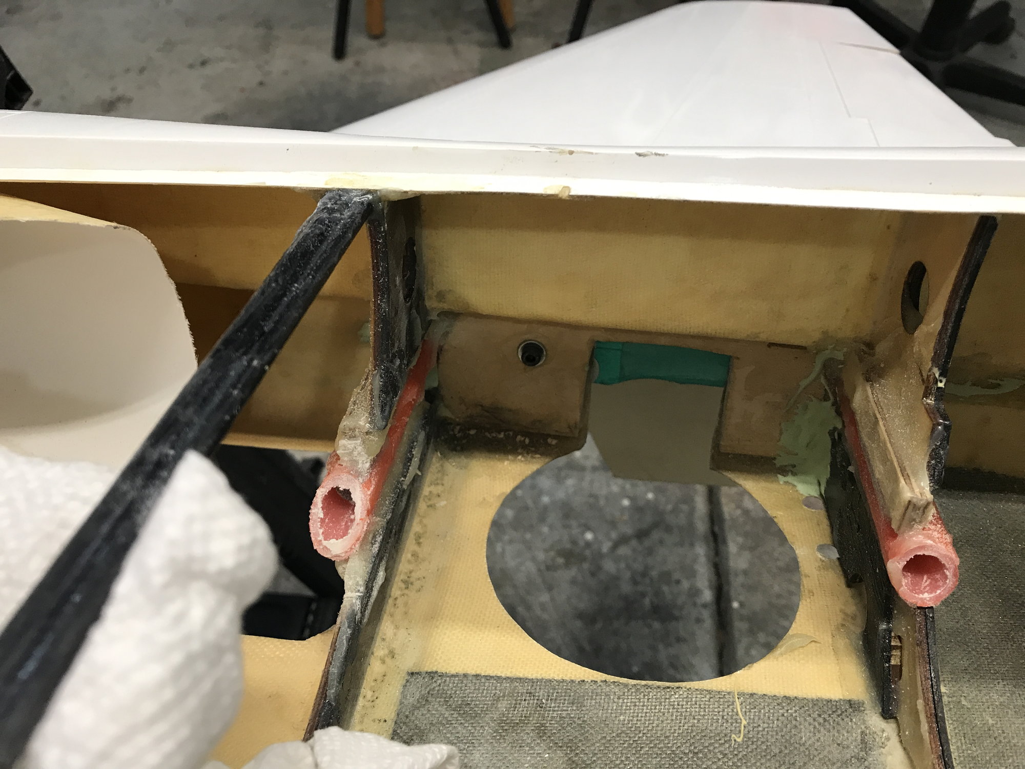
I have made the suggested cross brace from plywood. It also works as a block to hold the upper, header tank from sliding back (shown is a mock tank, not the real one). It will be 3 1/2 by 7 inches). The header tank is centered over the CG. My total fuel capacity will be 3.5 liters plus another 250cc in the air trap. The P-130 uses 500cc/min. I should get a good 7 min. of flight with plenty left over for a few go-arounds if needed.
You can also see the servos that actuate the main gear doors. These servos with hardware and arm weigh in at 17gm each. Again, I am going all electric. The aluminum cylinders with a foot of each air line also weigh in at 17gm each. They would have to be twice as long or more. Then there is the air line actuator, the servo to move it, the fill portal and pressure gauge as well as air storage tank. The weight saving in this circuit alone is significant.
01-19-2019, 03:01 PM
#68
If you want to make yours look like that , use titanium gold first than silver and black easy sanding primer then use 0000 steal wool to send the black and some silver so the gold from the bottom will be slightly visible and after use just the gold to fix the white bumps so the look titanium will post pictures after finishing.
01-23-2019, 04:20 AM
#69
Thread Starter

I finished installing the main gear and the quick connects for the servos and electrified gear (performed by Down and Locked). I still have to do a quick connect for the brake air line.
I removed most of the wire leads and connector from the servos and spliced in PowerBox twisted cables. They are directly connected to the back end of these MPX plugs. I have never had to replace these servos in planes so why have a failure point. If needed though I can just solder on new wires to the back of these removable connectors.
There is however a servo connector to the landing gear as these may need to come out for a repair. There will also be a connector on the air line behind the quick connect for the same ease of a repair if need. That way the gear can be disconnected easily and taken out of the wing. I always try to think of how something may fail and then the best way to repair it.
I do not use servo connector clips to secure connections but just tie them together with thread, cheaper and saves a gram of weight.
AEHaas
Last edited by aehaas; 01-23-2019 at 04:25 AM.
01-23-2019, 04:39 AM
#70
Thread Starter

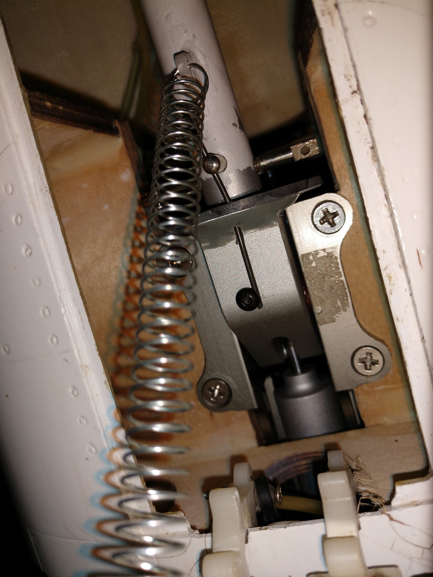
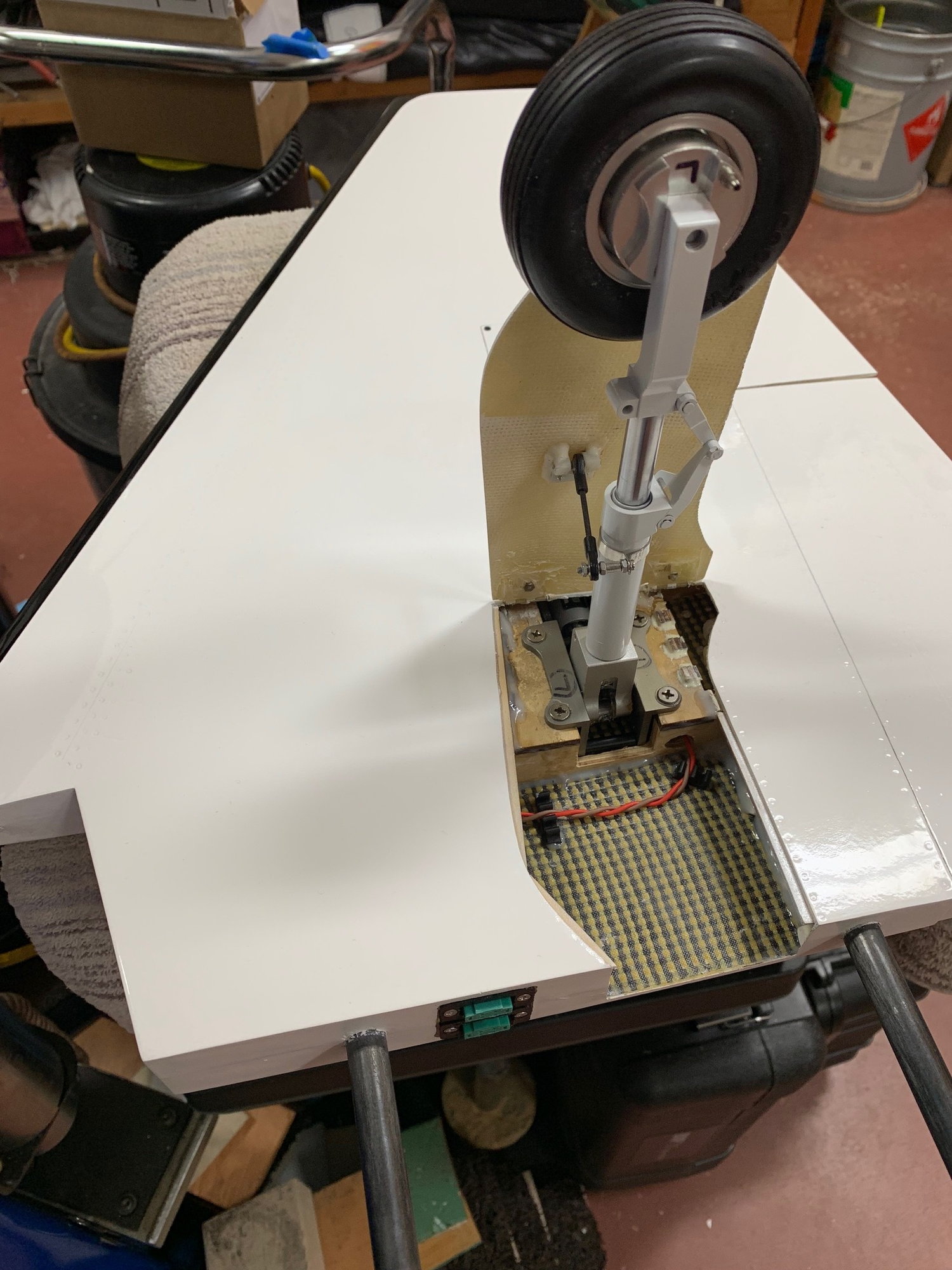
The nose gear is installed. The front end is done but for the areas where I will be installing/securing batteries. I used the custom servo steering tray I made as others have done.
Behind the nose gear former I made a ramp (painted grey). This way I just slide the front half of the two piece cockpit tray forwards and it finds it's place with ease and does not catch on anything.
AEHaas
01-23-2019, 09:24 AM
#72

I finished installing the main gear and the quick connects for the servos and electrified gear (performed by Down and Locked). I still have to do a quick connect for the brake air line.
I removed most of the wire leads and connector from the servos and spliced in PowerBox twisted cables. They are directly connected to the back end of these MPX plugs.
I removed most of the wire leads and connector from the servos and spliced in PowerBox twisted cables. They are directly connected to the back end of these MPX plugs.
 01-23-2019, 10:24 AM
#74
Thread Starter
Main strut = 156mm, wheel = 75mm
01-23-2019, 10:44 AM
#75
Thread Starter
Auburn02, I feel your pain on the connectors, 'will get back to that later.
I chose machined links for the hot environment in this area. I will however have a heat shield to protect the servo. I decided to make a barrier extend down from (and attached to) the elevator servo cover panel. It will strengthen the cover and not be in the way if service of the servo or links is needed. It would be out of the way as it would be removed with the cover panel.
AEHaas