


The Skymaster Northrop T-38 Talon Project of 2019


 01-30-2019, 10:07 AM
#102

Thread Starter
The white bottle on comment number 67 represents the header tank that sits above the main fuel cell. It is a cylinder about 3 1/2 by 7 or 8 inches long. The UAT pictured here will sit on the fuselage floor just behind the second pilot. It is around 250cc more:
I did the throws and expo settings as well as some of the mixes.
I am basically on hold now until I receive the custom header tank from Jet-Tech. It has not shipped as yet. Then I can do the fuel system and engine install. I do not want to do anything until I have it all in front of me and make sure it fits as planned.
AEHaas
 01-30-2019, 01:18 PM
#103
Thread Starter
I used a JetCat pitot tube up front inserted into a telescoping aluminum tube for extra length. It will be attached to the Spectrum Air Speed Sensor for telemetry read back of my actual airspeed. It is very useful during landings. I used black pinstripe for the proper look:

02-01-2019, 02:07 PM
#104
Thread Starter
The rate limiting step at this point is that I am waiting for Jet-Tech to send the custom header tank. Also, Down and Locked is sending another controller as this one is not saving one of my settings. It may be my computer, who knows but Mitch is nice enough to just send another controller to see if that does it. If I had these in hand and all was working OK then I should be able to maiden the plane about a week later.
For now I am working on my field stand. It will hold the plane upright even with one wing in place. I will have access to the rear wing bolts that must be tightened from the bottom. I tried to turn it around for access from the top but that would require major former surgery. Anyway I need the stand to test the gear and even for transport.
There is a wooden frame and the rest is expanded foam. It is light weight. The plane sits on a 1/4 inch thick piece of semi hard foam strips. This will be covered with 1/8 inch felt. The contact points have been formed to fit and distribute the planes weight evenly to prevent any deformity or dents on the skin.
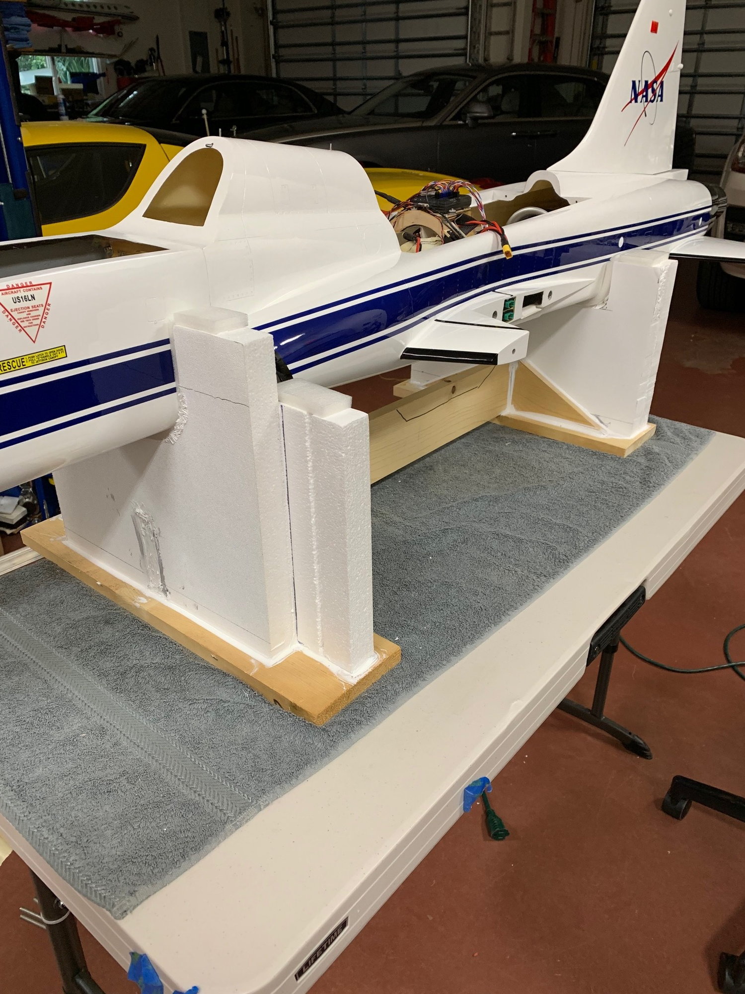
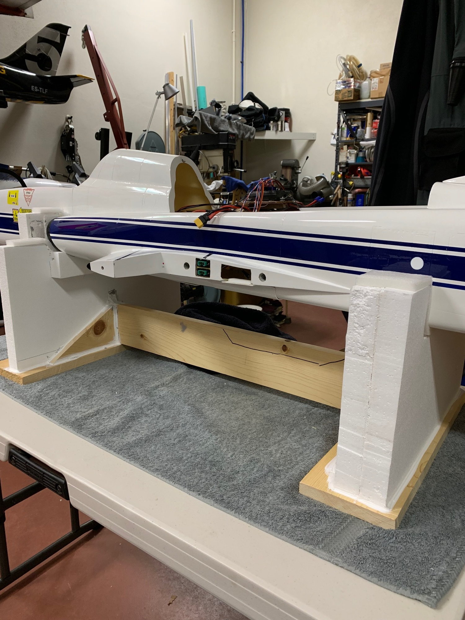
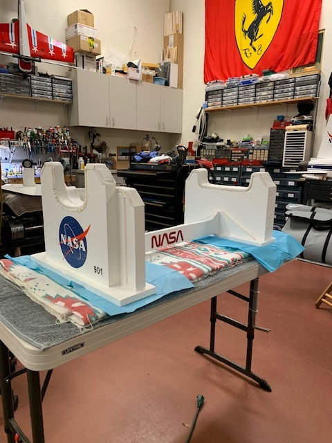
There is a lot to be done with the stand. I am not sure of the exact paint scheme but it should be as nice as the plane.
Here is my BVM L-39 stand:

AEHaas
For now I am working on my field stand. It will hold the plane upright even with one wing in place. I will have access to the rear wing bolts that must be tightened from the bottom. I tried to turn it around for access from the top but that would require major former surgery. Anyway I need the stand to test the gear and even for transport.
There is a wooden frame and the rest is expanded foam. It is light weight. The plane sits on a 1/4 inch thick piece of semi hard foam strips. This will be covered with 1/8 inch felt. The contact points have been formed to fit and distribute the planes weight evenly to prevent any deformity or dents on the skin.
There is a lot to be done with the stand. I am not sure of the exact paint scheme but it should be as nice as the plane.
Here is my BVM L-39 stand:
AEHaas
 02-05-2019, 09:54 AM
#107
My Feedback: (4)
The rate limiting step at this point is that I am waiting for Jet-Tech to send the custom header tank. Also, Down and Locked is sending another controller as this one is not saving one of my settings. It may be my computer, who knows but Mitch is nice enough to just send another controller to see if that does it. If I had these in hand and all was working OK then I should be able to maiden the plane about a week later.
For now I am working on my field stand. It will hold the plane upright even with one wing in place. I will have access to the rear wing bolts that must be tightened from the bottom. I tried to turn it around for access from the top but that would require major former surgery. Anyway I need the stand to test the gear and even for transport.
There is a wooden frame and the rest is expanded foam. It is light weight. The plane sits on a 1/4 inch thick piece of semi hard foam strips. This will be covered with 1/8 inch felt. The contact points have been formed to fit and distribute the planes weight evenly to prevent any deformity or dents on the skin.
AEHaas
What is the white glue you use to hold the foam to the wood?
Patrick
02-05-2019, 11:57 AM
#108
Thread Starter
"Ali,
What is the white glue you use to hold the foam to the wood?
Patrick"
Good question Patrick. This stuff came from Lowes in the construction area, not the paint isle. It is a VERY Sticky soft polyurethane caulk-like adhesive. It does not shrink and seems to last forever. It is easy to flow onto things but impossible to get off as it is just so very sticky. It is great for a lot of things. It sticks to just about everything. The downside is that it does not become tacky for 12-18 hrs. It will dry to the touch in about 24 hours but takes 5 days or so to fully cure.
02-09-2019, 07:21 AM
#109
Thread Starter
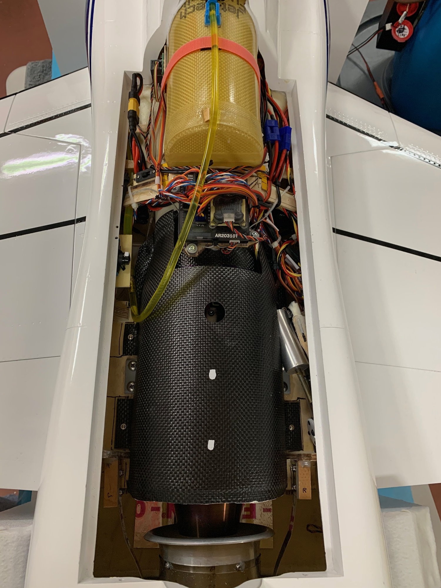
I have completed the installation of the fuel cells, piping and turbine electronics. I am about ready to test the new JetCat P-130 engine.
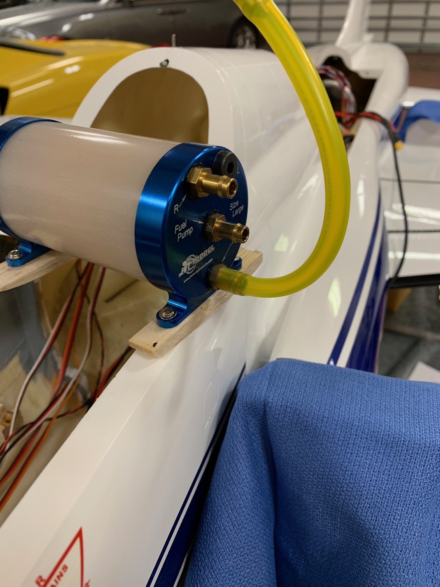
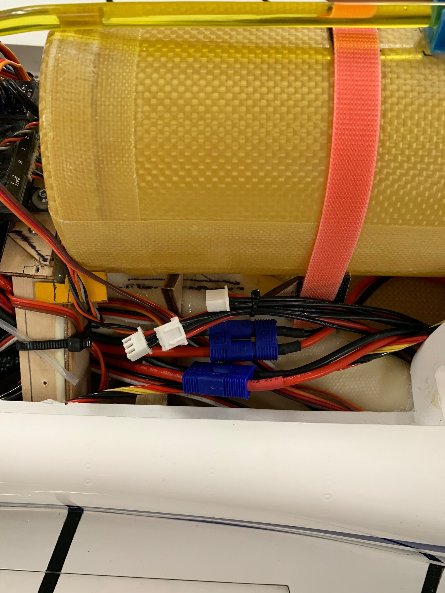
You can see the header cell here. It is nearly centered over the CG. The tank filler tube with stopcock is at the top. Note that it is a Festo valve. You generally should not use these on the suction side as done here but they are suction rated enough for this application as long as the tubing is hard and the right size. Mine is a nice tight fit. The long hose allows for fueling off of the edges of the plane in case there is a spill.
Also seen is the Velcro strap to help hold the tank and also keeps it from rotating as there is a Velco piece on the tank itself as well.
On the lower left is the IO board for the ECU. It can be used to connect an external GSU for programming. Now it is connected to my Spektrum telemetry JetCat module (not seen) so I can see turbine data from the transmitter. The yellow connector is to the 9.9v LiFe battery that powers the ECU and Gear Controller. On the lower right is the main Receiver switch.

Here is a view from the cockpit side. I used 3/16 ID connectors and 8mm Tygon. It was reduced to 6mm, then 4mm as it went into the pump. All was safety wired. The header tank is vented at the fuselage bottom to a BVM "taxi tank" connector. There is a Festo reducer there as the 8mm Tygon needed reduction to 6mm tubing to connect. The tank connectors are from Jet-Tech and not the Skymaster supplied rubber plugs. The JetCat ECU is Velco'ed to the Velco main fuel cell retaining strap. Blurry in the foreground is the air trap. It extends mostly into the front fuselage. I always fill air traps with fuel for balancing.

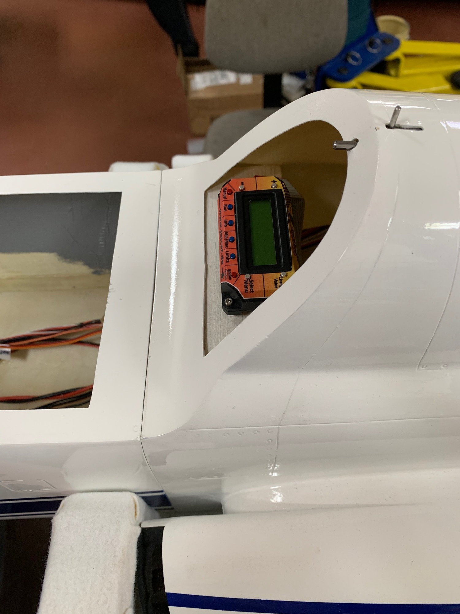
Here is the onboard JetCat ECU that can be viewed through the canopy but it must be removed to work the buttons if needed.
The pilots with light blue uniforms should be here Monday.
I am having trouble with the new software of the Down and Locked gear controller. We are working on this and should get it resolved shortly. The final balancing should be in a few days. Then I will be ready to take it up for a maiden flight!
AEHaas
You can see the header cell here. It is nearly centered over the CG. The tank filler tube with stopcock is at the top. Note that it is a Festo valve. You generally should not use these on the suction side as done here but they are suction rated enough for this application as long as the tubing is hard and the right size. Mine is a nice tight fit. The long hose allows for fueling off of the edges of the plane in case there is a spill.
Also seen is the Velcro strap to help hold the tank and also keeps it from rotating as there is a Velco piece on the tank itself as well.
On the lower left is the IO board for the ECU. It can be used to connect an external GSU for programming. Now it is connected to my Spektrum telemetry JetCat module (not seen) so I can see turbine data from the transmitter. The yellow connector is to the 9.9v LiFe battery that powers the ECU and Gear Controller. On the lower right is the main Receiver switch.
Here is a view from the cockpit side. I used 3/16 ID connectors and 8mm Tygon. It was reduced to 6mm, then 4mm as it went into the pump. All was safety wired. The header tank is vented at the fuselage bottom to a BVM "taxi tank" connector. There is a Festo reducer there as the 8mm Tygon needed reduction to 6mm tubing to connect. The tank connectors are from Jet-Tech and not the Skymaster supplied rubber plugs. The JetCat ECU is Velco'ed to the Velco main fuel cell retaining strap. Blurry in the foreground is the air trap. It extends mostly into the front fuselage. I always fill air traps with fuel for balancing.
Here is the onboard JetCat ECU that can be viewed through the canopy but it must be removed to work the buttons if needed.
The pilots with light blue uniforms should be here Monday.
I am having trouble with the new software of the Down and Locked gear controller. We are working on this and should get it resolved shortly. The final balancing should be in a few days. Then I will be ready to take it up for a maiden flight!
AEHaas
02-09-2019, 07:58 AM
#110


All looking great except the tygon going on to Festo fitting ,the tygon will eventually give up and might cost air leaks,I stopped using the Festo valves long time ago and never used them on fill and and suction applications ,usually I�m just using the regular push pug to close the fuel line and only like in two Jets I have the Festo valve on the vent and using it just for the jet transportation in my van .
Last edited by sysiek; 02-09-2019 at 08:07 AM.
02-10-2019, 08:18 AM
#111
Thread Starter
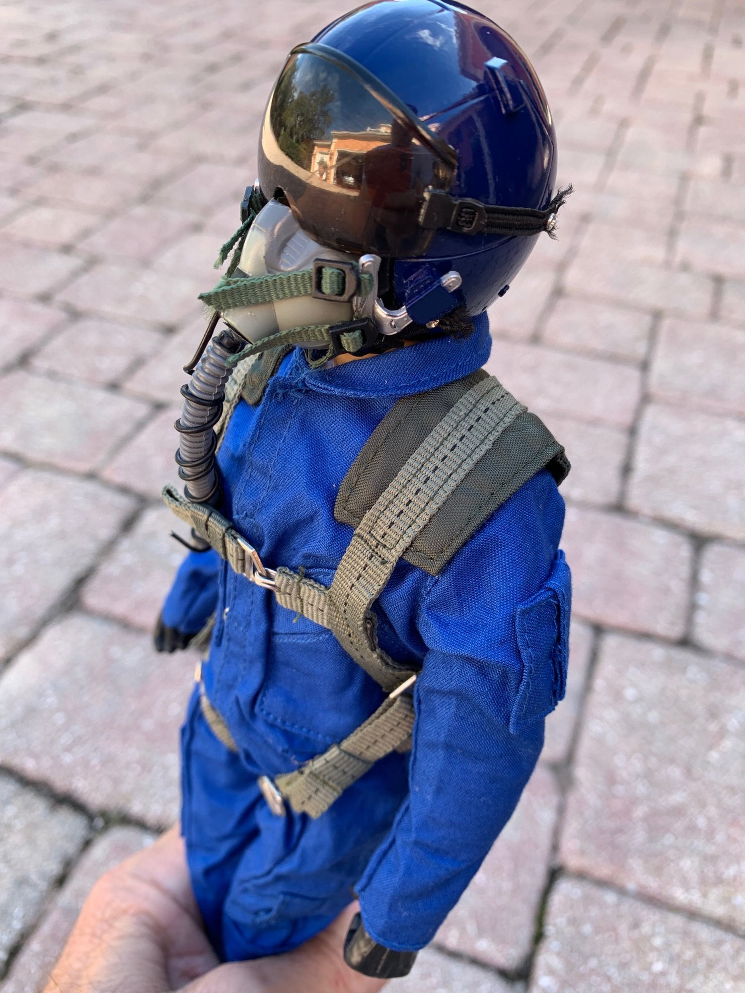
I actually received the pilots yesterday from Adam at www.warbirdpilots.com
He made up some light blue colored suits and painted the helmets the NASA colors. I added the NASA emblem to the chest and American flag to the arm. These pilots are not the plastic ones I showed in an earlier photo. These are actually a cotton stuffed wire skeleton. They only weigh in at I think 4.2oz each. I still took off the boots to save a little more weigh as they cannot be seen anyway.
I secured the pilots with Velcro on the seat bottoms and backs.

I filled the air trap with fuel and filled the main fuel cell about 5-10 percent. I may well get to balancing the plane later today.
AEHaas
He made up some light blue colored suits and painted the helmets the NASA colors. I added the NASA emblem to the chest and American flag to the arm. These pilots are not the plastic ones I showed in an earlier photo. These are actually a cotton stuffed wire skeleton. They only weigh in at I think 4.2oz each. I still took off the boots to save a little more weigh as they cannot be seen anyway.
I secured the pilots with Velcro on the seat bottoms and backs.
I filled the air trap with fuel and filled the main fuel cell about 5-10 percent. I may well get to balancing the plane later today.
AEHaas
02-10-2019, 09:58 AM
#113
Thread Starter
The header tank is a little over 3 1/2 by 7" giving me around 1100cc internally, plus or minus, according to my calculation. I measured the water I filled the main fuel cell giving me 2600cc there. So a total with both cells of around 3,700cc. Plus another 250cc in the air trap. The header tank is centered over the CG of the plans at about 100-105mm but the heavy clunk is behind the CG. The main tank has about 10-15 percent of the volume behind the CG and it's clunk is probably just behind the CG. As the P-130 JetCat turbine is supposed to use 500cc per minute at full throttle I should get 7 minutes of flying at full throttle.
I did the penultimate CG measurement just now. It will be balanced at 115mm when I put in the power and charging wires for the second receiver battery. This is with a location in the tip of the nose under the pitot tube. At our field I have found that Skymaster planes are always nose heavy at first. I think they are very conservative that way so I am happy here as a starting point. My guess is that I will have to move it back eventually. I will only know this after a few test flights.

I have yet to install the Spektrum AS3000 gyro but it weighs nothing.
The balance point was the same when I held up the plane with my fingers at the CG so all is consistent. The total weight of the plane at this point with some fuel in the main fuel cell and the air trap full came out to 28.7 lbs.
I will be able to go vertical but not for very long. Still, it should do everything else I may ask for.
AEHaas
I did the penultimate CG measurement just now. It will be balanced at 115mm when I put in the power and charging wires for the second receiver battery. This is with a location in the tip of the nose under the pitot tube. At our field I have found that Skymaster planes are always nose heavy at first. I think they are very conservative that way so I am happy here as a starting point. My guess is that I will have to move it back eventually. I will only know this after a few test flights.
I have yet to install the Spektrum AS3000 gyro but it weighs nothing.
The balance point was the same when I held up the plane with my fingers at the CG so all is consistent. The total weight of the plane at this point with some fuel in the main fuel cell and the air trap full came out to 28.7 lbs.
I will be able to go vertical but not for very long. Still, it should do everything else I may ask for.
AEHaas
Last edited by aehaas; 02-10-2019 at 10:21 AM.
02-11-2019, 05:59 PM
#114
Thread Starter
02-12-2019, 05:20 PM
#115
Thread Starter
I am ready for an engine run tomorrow. All systems seem to be working.
Here is the engine compartment. As stated by another, the lower bypass duct needed to be heavily modified to fit around everything, formers, tires, gear door hinges, the engine mount et cetera. There is BVM heat resistant paint and some reflecting aluminum to protect things at the rear of the bypass. The fuel tubing and single engine connection wiring harness is draped in the center for now.
You can see the large, single piston, BVM air braking system. A very strong servo gives proportional braking. It uses a very small lumen tubing. The system works very well. All my airline connections to the wing are the auto-connect pieces by BVM and works as my electrical connections. You push on the wings and everything is automatically connected, no fuss, nothing to go wrong.
At the upper left behind all those wires is the Down and Locked gear controller Vecro'ed to the sidewall. The plywood engine mounts were crooked. One side needed to be shaved and the other side built out. I added a second piece of plywood underneath to strengthen it and give a better purchase for my engine screws.

The engine is screwed down using truss head wood screws. I do not have to worry about fitting nuts and bolts. I always use a little canopy glue on screws as these to prevent them from backing out.
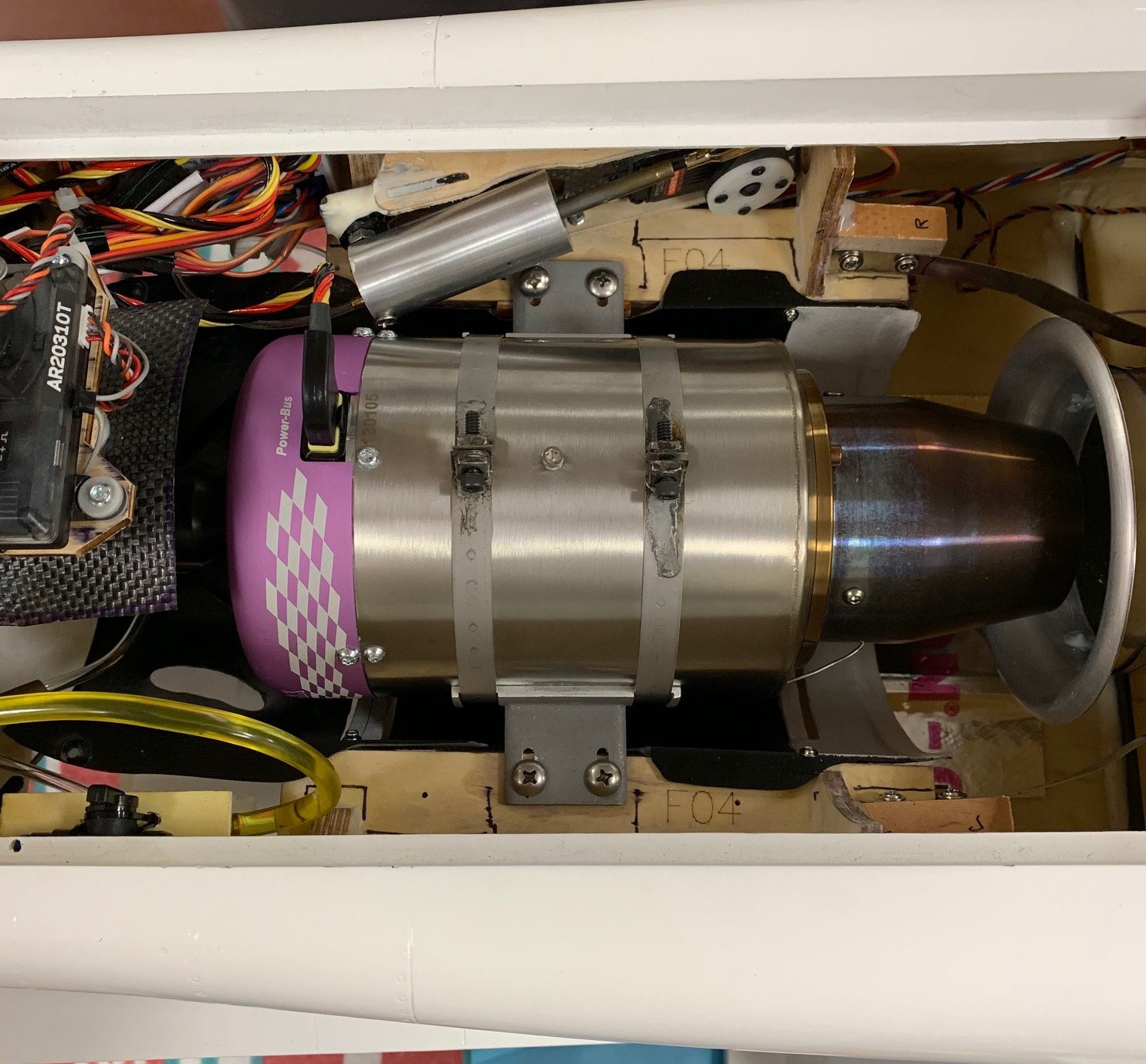
I will test the engine. If all goes well I will put on the upper bypass cover. It too needed some plastic surgery to fit around things.
AEHaas
Here is the engine compartment. As stated by another, the lower bypass duct needed to be heavily modified to fit around everything, formers, tires, gear door hinges, the engine mount et cetera. There is BVM heat resistant paint and some reflecting aluminum to protect things at the rear of the bypass. The fuel tubing and single engine connection wiring harness is draped in the center for now.
You can see the large, single piston, BVM air braking system. A very strong servo gives proportional braking. It uses a very small lumen tubing. The system works very well. All my airline connections to the wing are the auto-connect pieces by BVM and works as my electrical connections. You push on the wings and everything is automatically connected, no fuss, nothing to go wrong.
At the upper left behind all those wires is the Down and Locked gear controller Vecro'ed to the sidewall. The plywood engine mounts were crooked. One side needed to be shaved and the other side built out. I added a second piece of plywood underneath to strengthen it and give a better purchase for my engine screws.
The engine is screwed down using truss head wood screws. I do not have to worry about fitting nuts and bolts. I always use a little canopy glue on screws as these to prevent them from backing out.
I will test the engine. If all goes well I will put on the upper bypass cover. It too needed some plastic surgery to fit around things.
AEHaas
02-13-2019, 05:48 AM
#116
Thread Starter
A few more pictures of the install:
We have leads for the electric gear, 2-gear doors, steering, remote receiver and air speed telemetry module. The two 2-cell receiver and single 3-cell ECU batteries have power leads and charging leads headed to the rear. Everything is harnessed.
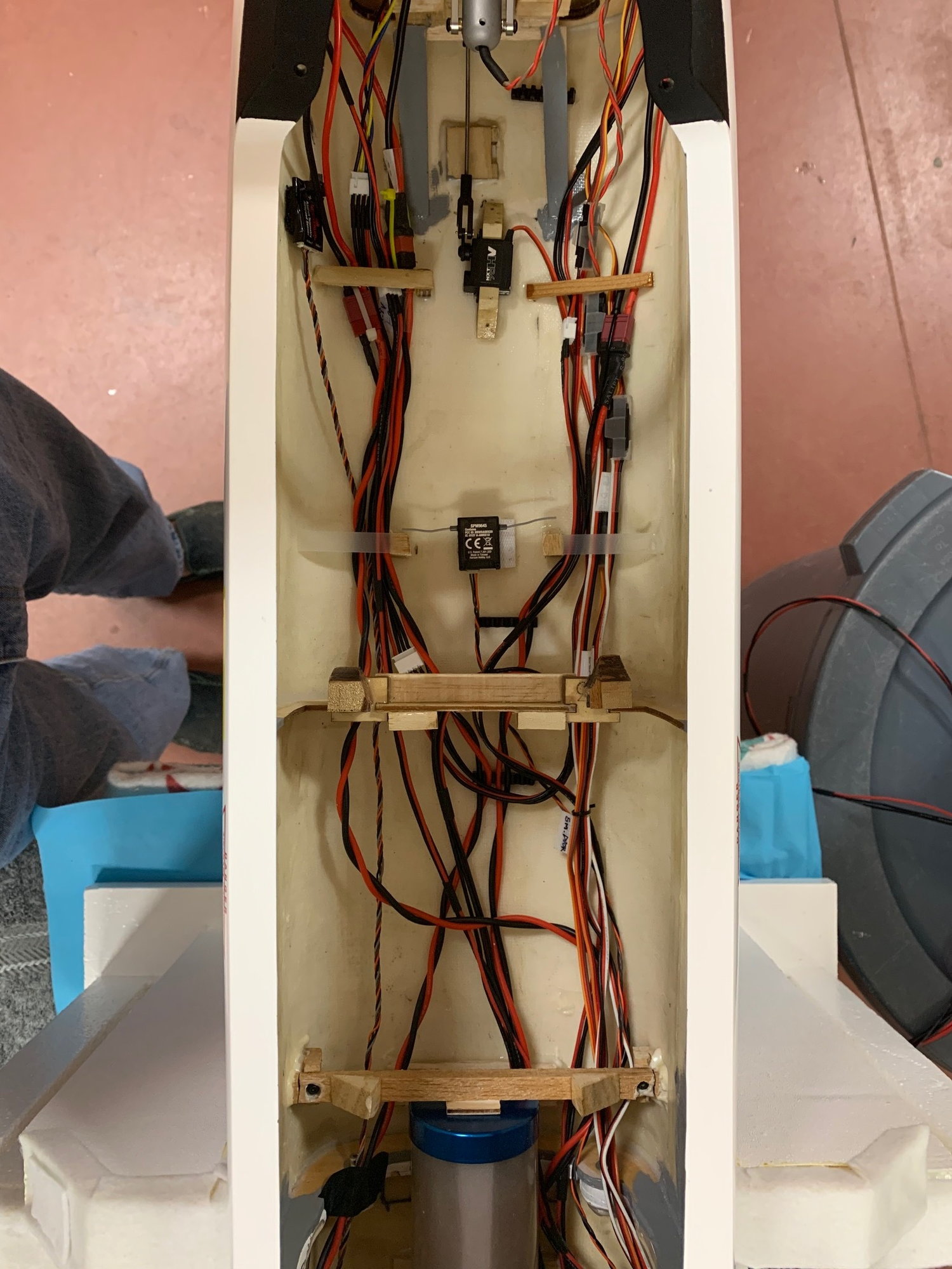
We have leads for the electric gear, 2-gear doors, steering, remote receiver and air speed telemetry module. The two 2-cell receiver and single 3-cell ECU batteries have power leads and charging leads headed to the rear. Everything is harnessed.
02-13-2019, 05:53 AM
#117
Thread Starter
Wheel brake air connector tweak. The nipples were hitting the bottom of the bypass so I switched them around.
Original lower location:
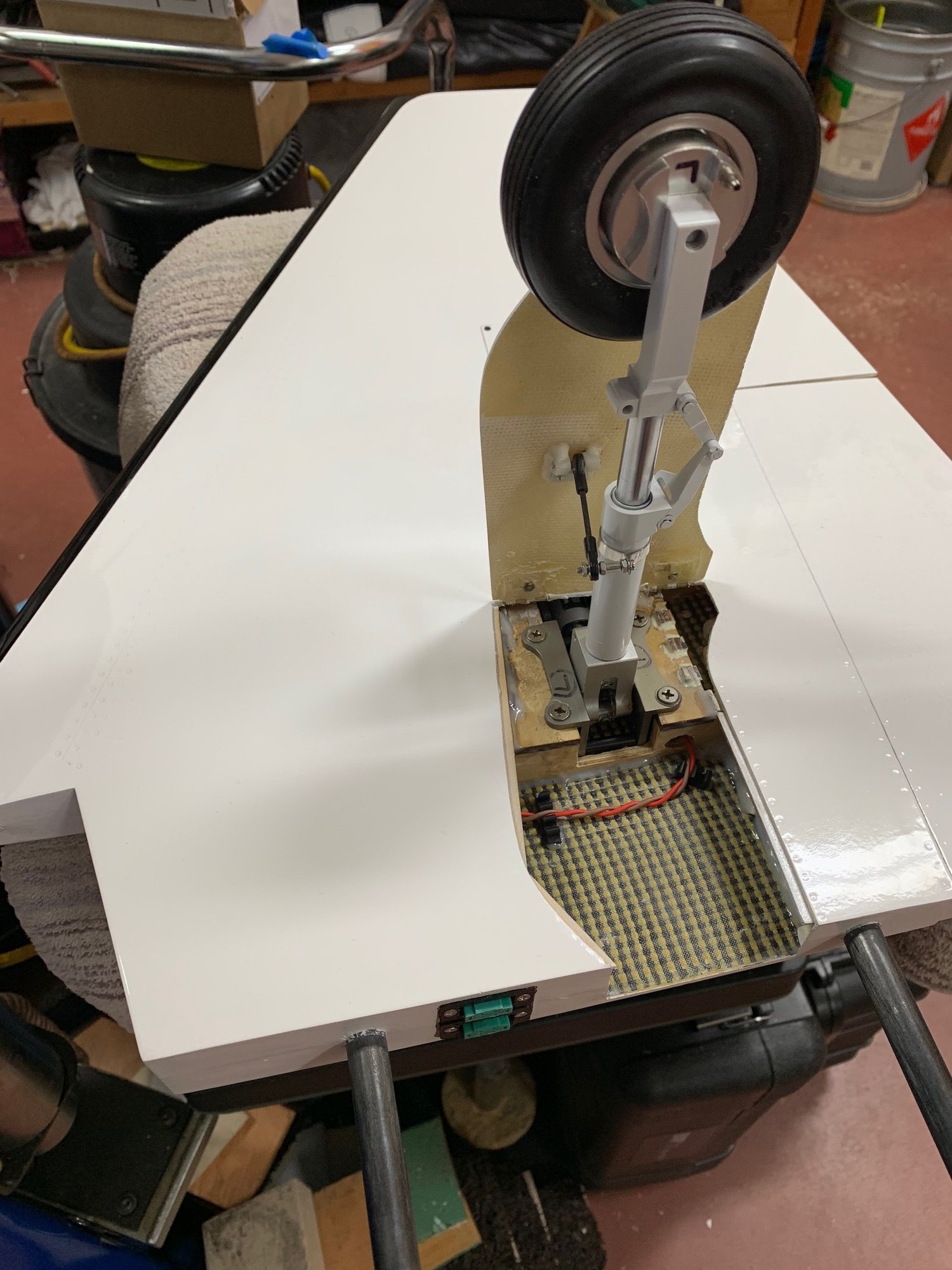
Moved so it does not hit the bypass when retracted:

Original lower location:
Moved so it does not hit the bypass when retracted:
02-13-2019, 06:04 AM
#118
Thread Starter
I charge by connecting to the JST connector balance leads from the engine compartment. I do not hook up directly to the batteries nor remove them. These are LiFe batteries though.
The charging leads to connect to the charger need a balance connector and banana plugs for the high and low. Shown here is how I made these. The banana plugs just splice into a JST extension into the high voltage (in this case 6.6v lead) and the ground. This adapter can by made for any amount of cells and can be used for LiPo cells as well. I prefer not to charge LiPo cells inside panes though.

You are limited however to a 3 amp charge. JST connectors have this limit. I charge at 2 amps.
AEHaas
The charging leads to connect to the charger need a balance connector and banana plugs for the high and low. Shown here is how I made these. The banana plugs just splice into a JST extension into the high voltage (in this case 6.6v lead) and the ground. This adapter can by made for any amount of cells and can be used for LiPo cells as well. I prefer not to charge LiPo cells inside panes though.
You are limited however to a 3 amp charge. JST connectors have this limit. I charge at 2 amps.
AEHaas
02-13-2019, 07:07 AM
#120
Thread Starter
02-13-2019, 09:26 AM
#121
Thread Starter
OK, I tested the turbine in a light drizzle. Conditions: somewhat gusty, 99% humidity, pressure of 30.16, 61F, 16' above sea level.
The engine started right up but I later brought the throttle up too fast, turbines cannot respond fast enough under these conditions. They sputter. Mine stopped suddenly with a low RPM fault. That was because it detected a high throttle level position but the engine could not roll up there fast enough. I restarted and brought the throttle up more slowly and all worked well.
For the moment I will put the airplane in the hanger. I want to fly something else a few times as I have not been at the field for a few months. Maybe I'll take out the 'ol Turbinator.
AEHaas
 02-13-2019, 12:34 PM
#123
Thread Starter
I did some calculations for CG from this site:
Aircraft Center of Gravity Calculator
It was very interesting to me. The Skymaster plans say to use a CG back 90 to 110mm. Let�s use the midpoint of 100mm as a single starting point. Recall I have found that other modelers have noticed their Skymaster planes to be too nose heavy using the recommended Skymaster CG midpoint. While one modeler of this airplane chose to use 108mm I planned on starting at 115mm back. I am currently balanced at this point.
The theoretical CG using the above calculations on this model is 123mm with a middle of the road 10% static margin. I am still guessing that I will end up moving the CG back a little more when I finally get things to my liking.
AEHaas
02-13-2019, 03:28 PM
#124
Thread Starter
'About the formula. I have used it before. I made a Ziroli Turbinator. I used anhedral instead of dihedral on the horizontal stabs. I swept the wings back (Nick said I could do this but warned that the CG would change). I made the CG point exactly what this formula said it should be. It worked out to be the exact place I ended up using. I trust this formula.
AEHaas
AEHaas


