


SU-57. Printed, laminated...
 10-14-2019, 11:50 PM
#1

Thread Starter
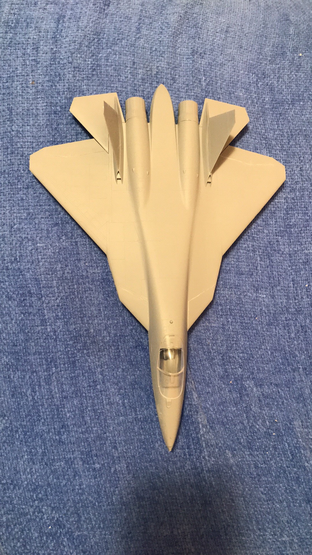
I have built up it in 8 months by working hard.
I can share here how I did and my experience by photos if you want after reading acknowledgements.
Acknowlegements
1. I am an hobbiest not pro (I am an aesthetic surgeon).
2. This is my first project especially in using fusion 360 program, performing lamination, finding cg etc.
3. There are some scale malformations e.g. cockpit, main gears, torso etc since the 3D drawing that I only found and used one has some of them. I saw them lately. But now trying to correct them.
4. Maiden was done when the sun went away so the video is not good. For fear of any heart condition, a friend of mine maidened the plane.
...


 10-15-2019, 06:30 AM
#3
Thread Starter
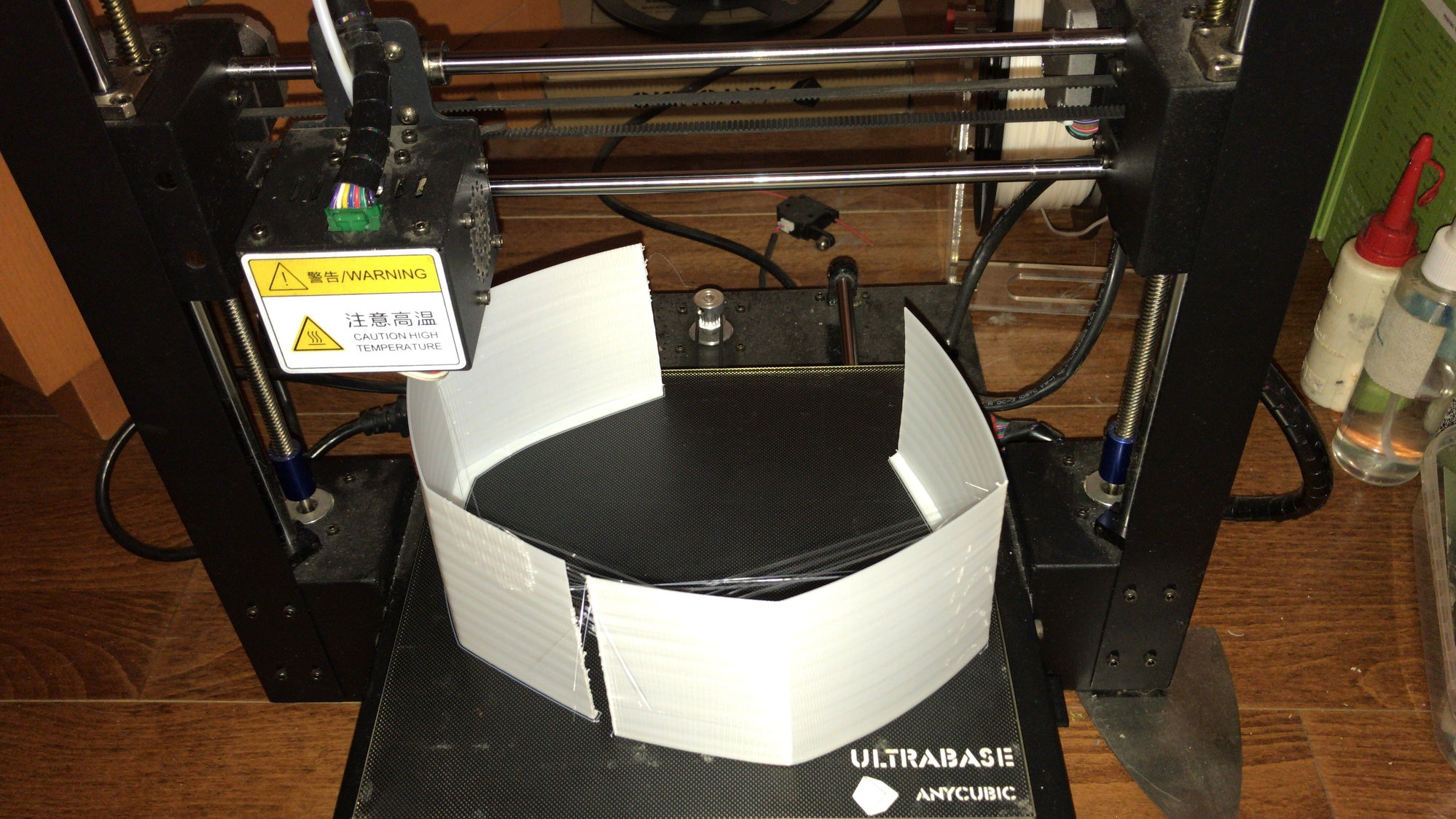
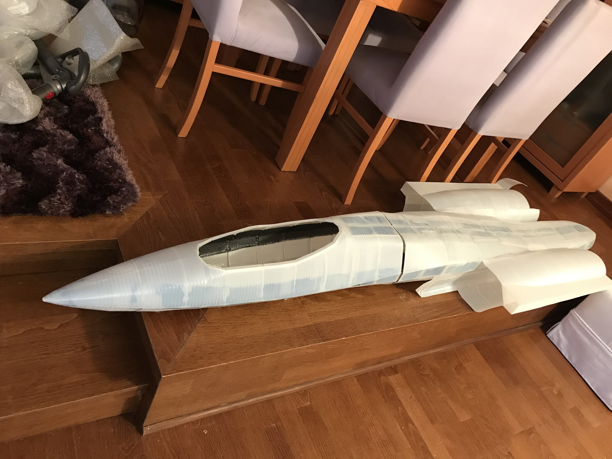
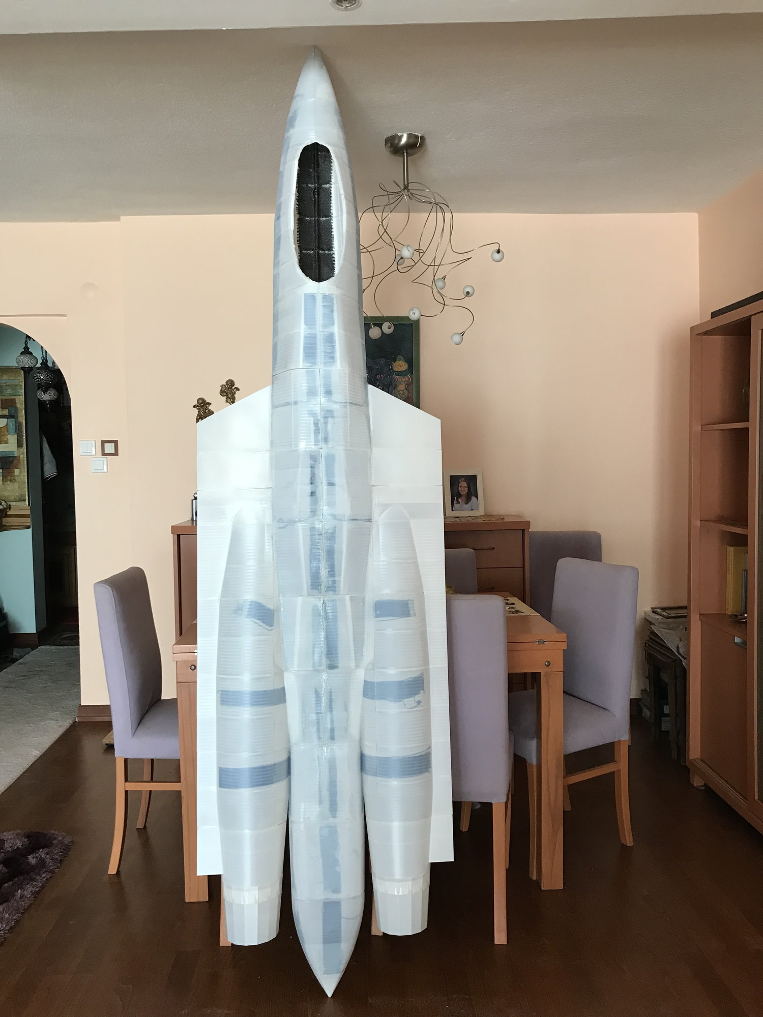
Yes. The body all printed and wings ruddders and elevators have printed spars. Plywood were used where needed. Glass-fabric laminated on all surfaces and some strips of carbon-fiber fabric inside were used.

 10-15-2019, 07:39 PM
#6
Thread Starter
Thanks a lot for your attention.
Modelling
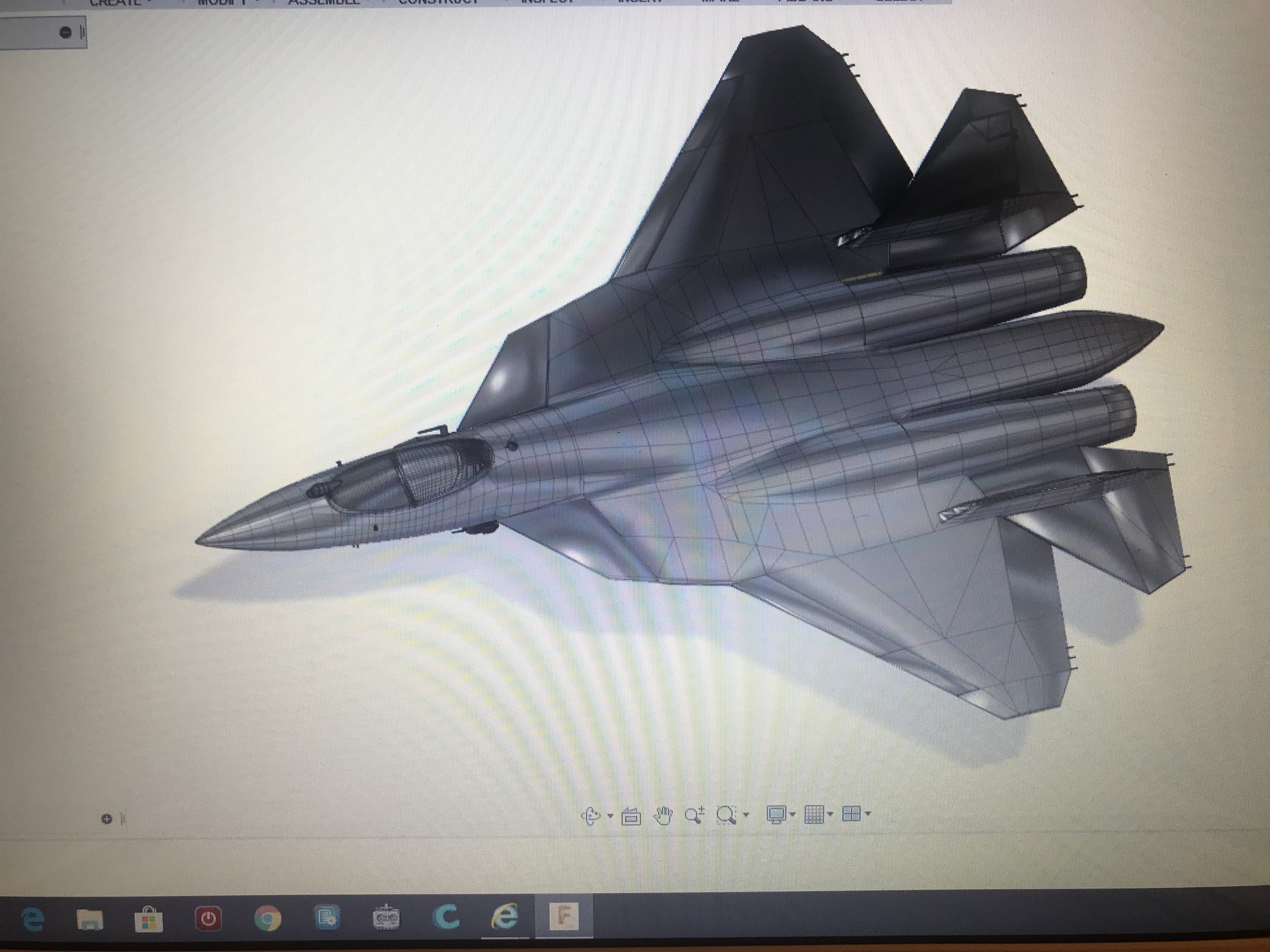
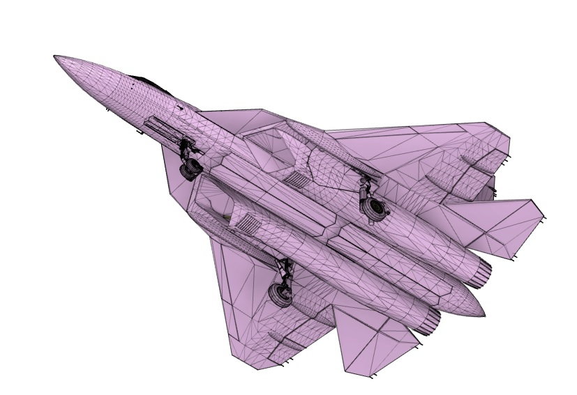
First of all, I found a small 1/72 size display model of Su-57. I tried to have a detailed (Professional) 3D scan of model. But it is very expensive in my country. A friend of mine found me 3D drawings at the internet. I checked and controlled the backside of the plane because of some clear points. So decided to use this drawing.
10-15-2019, 08:27 PM
#7
Thread Starter
Computer work (I am not an expert)
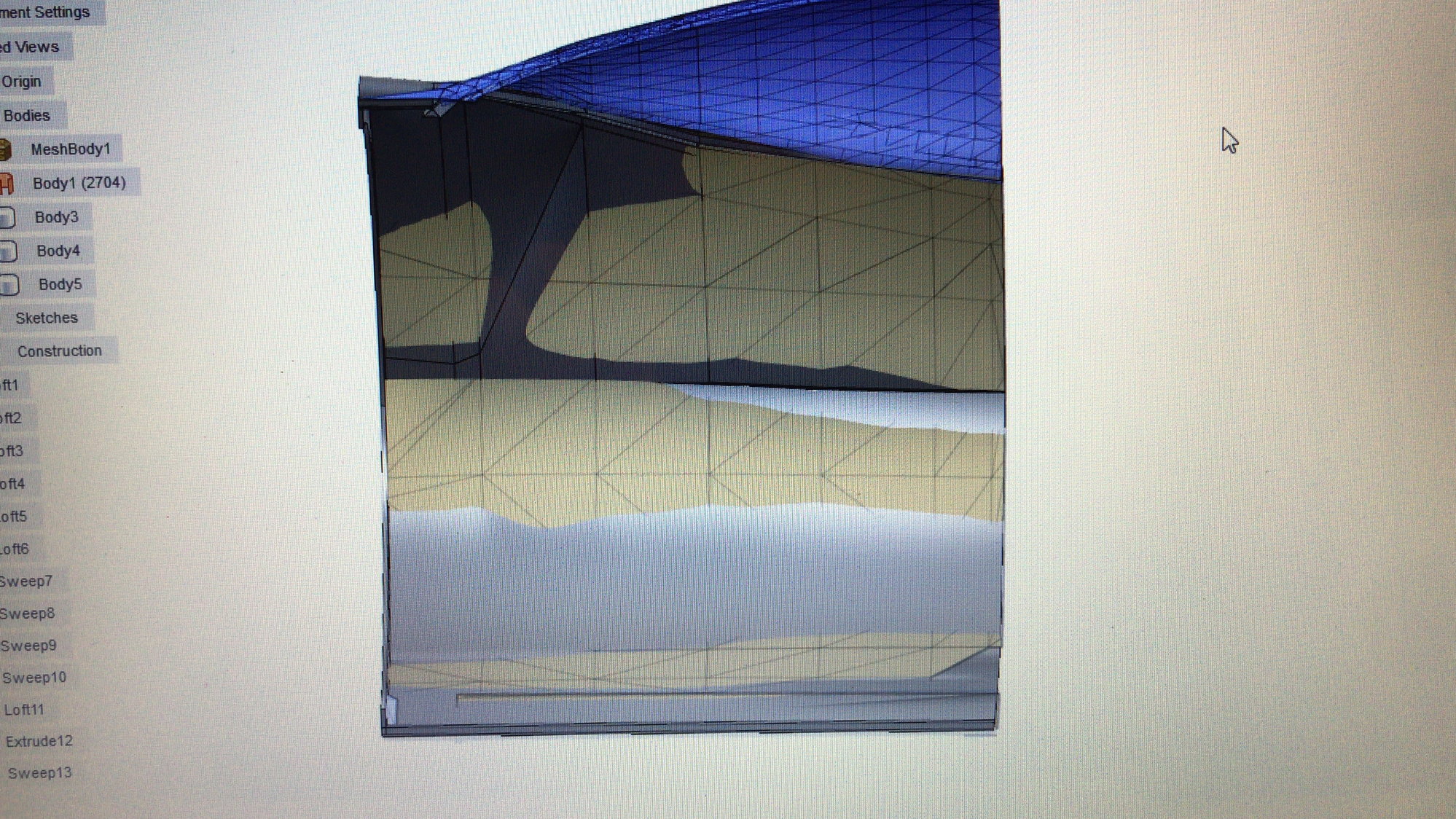
I tried to open this drawing which is in .stl format in Fusion360 program. But the drawing has lots of triangles so the program can not change it to a body in order to work on it.
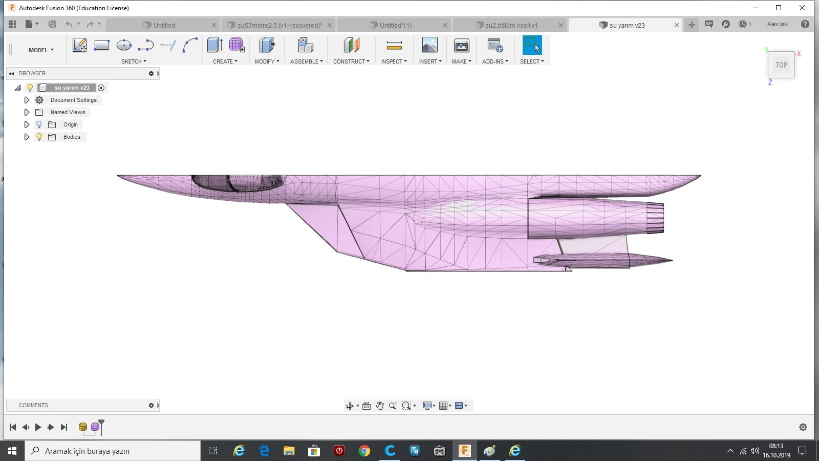
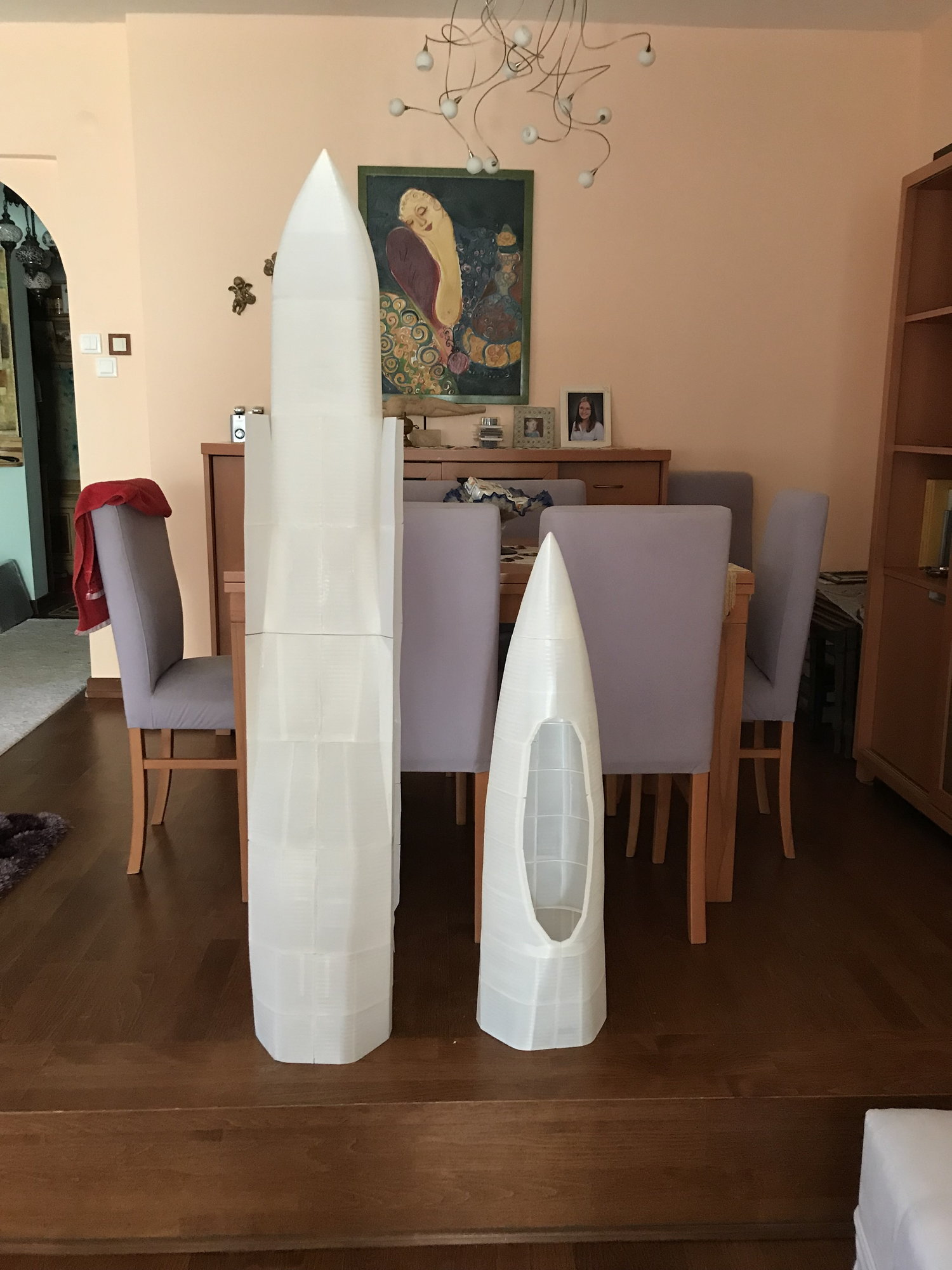
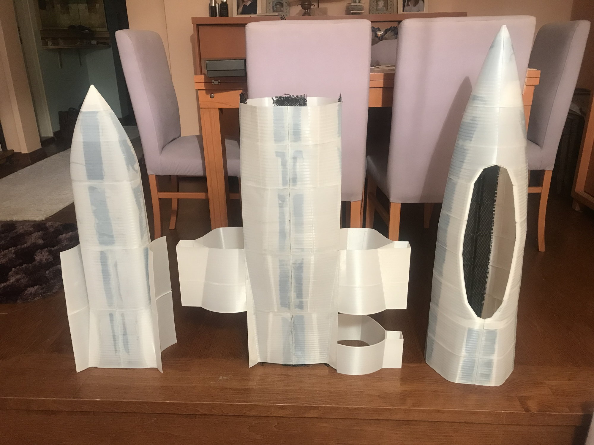
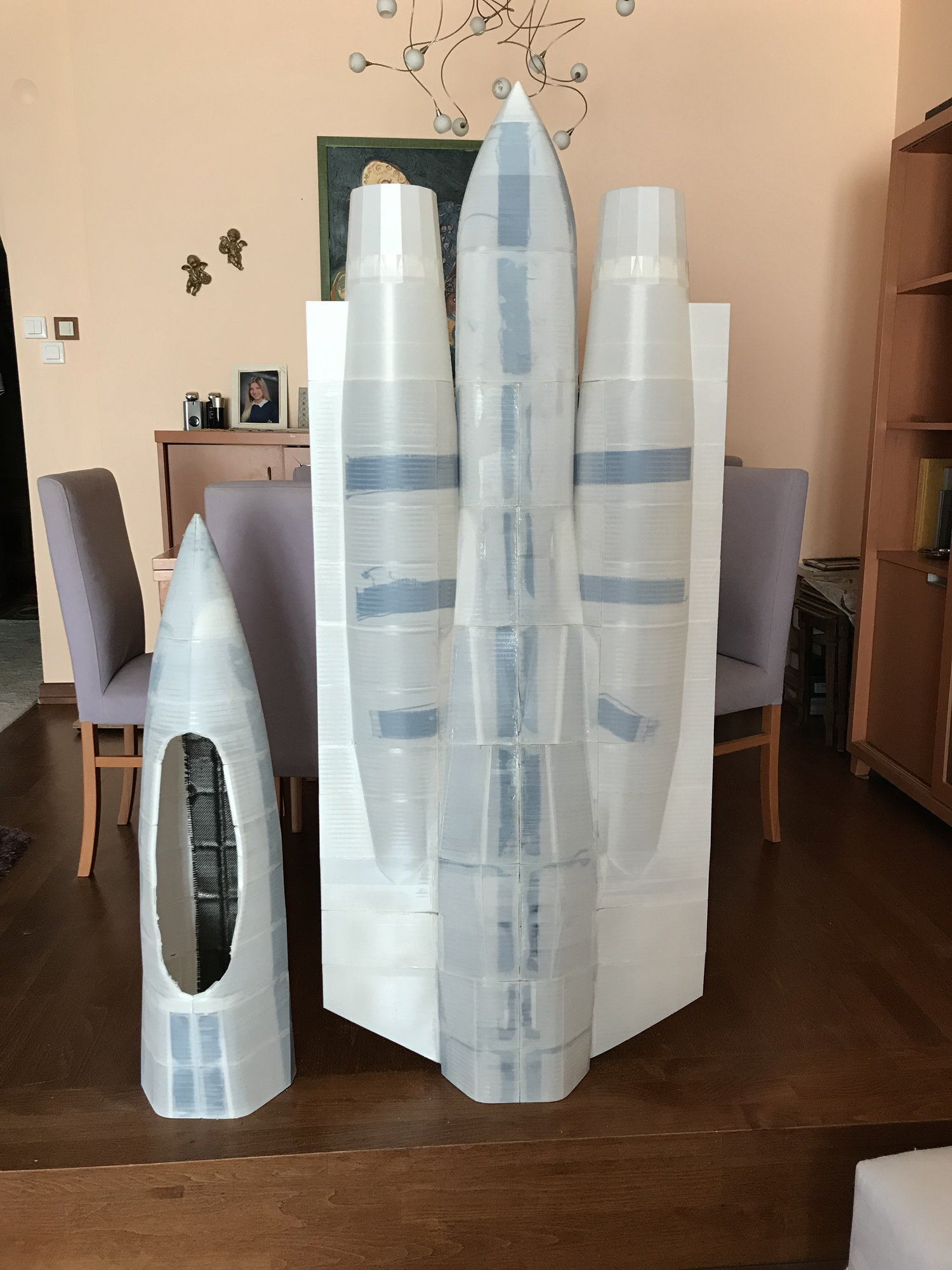
Than I opened it in Meshmixer program; resized it to 2,5 m of body length. Cut the body half. Cut the wings. Sliced the remaining body part horizantally. less than 20 cm and saved each slice.
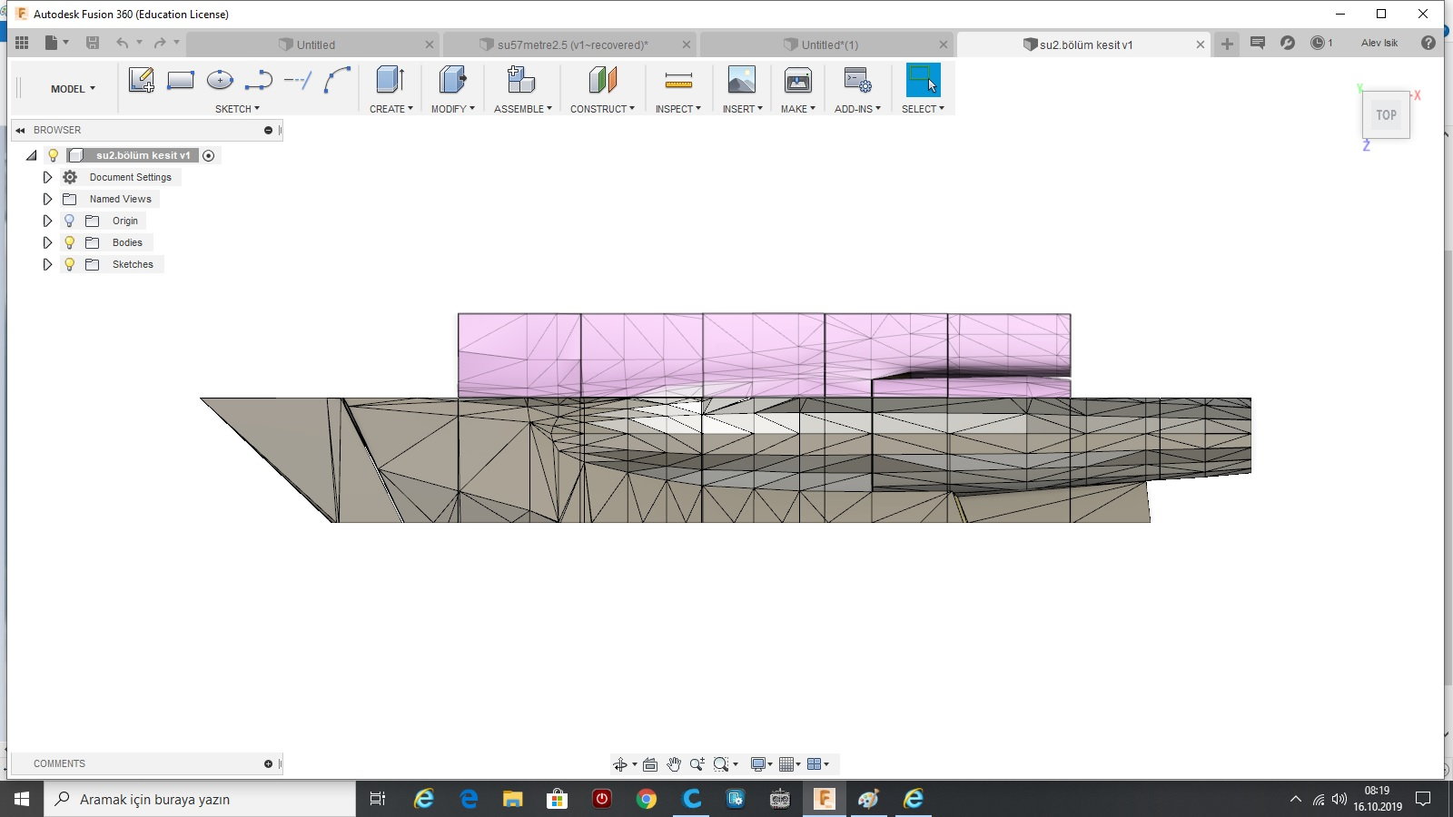
I opened these slices in Fusion 360 program and cut them vertically less than 20 cm again. Even at this stage, since the program can not give a body to work on I drawed rectangles very thin in width (less than 0.5 mm) and used extrude cutter. So I achieved drawings of each segment which are less than 20x20x20 cm.
Ps. There is some problem and I can not upload the photos at the moment.
I tried to open this drawing which is in .stl format in Fusion360 program. But the drawing has lots of triangles so the program can not change it to a body in order to work on it.
Than I opened it in Meshmixer program; resized it to 2,5 m of body length. Cut the body half. Cut the wings. Sliced the remaining body part horizantally. less than 20 cm and saved each slice.
I opened these slices in Fusion 360 program and cut them vertically less than 20 cm again. Even at this stage, since the program can not give a body to work on I drawed rectangles very thin in width (less than 0.5 mm) and used extrude cutter. So I achieved drawings of each segment which are less than 20x20x20 cm.
Ps. There is some problem and I can not upload the photos at the moment.
 10-15-2019, 09:44 PM
#9
Thread Starter
After achieving segments, I draw base and up sketches (one of them is usually copy-paste of before one) a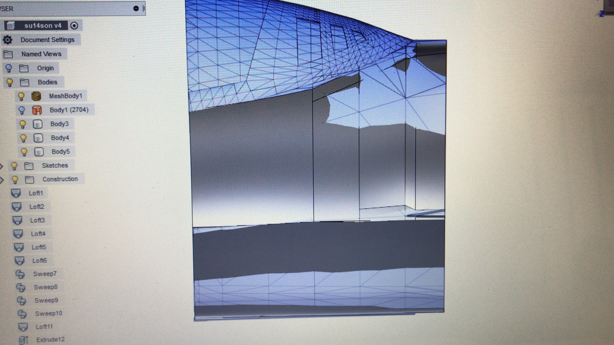
and after drawing one edge usually used 0.8 mm offset of that edge, so created the sketch; made lofts in Fusion 360 program. And always checked the shapes of meshbody (segment) and body that I created.
and after drawing one edge usually used 0.8 mm offset of that edge, so created the sketch; made lofts in Fusion 360 program. And always checked the shapes of meshbody (segment) and body that I created.
 10-15-2019, 10:01 PM
#11
Thread Starter
I really don't want to get a Professional help in this Project. I only want to do everything by myself. Fusion360 is a very easy to learn 3D program.
Or you can get a pro help.
You may use a pro 3D scanned model, may use a very complicated 3D programs and cut the segments very easily.
Ps. Please write comments or questions so we can learn more.
Or you can get a pro help.
You may use a pro 3D scanned model, may use a very complicated 3D programs and cut the segments very easily.
Ps. Please write comments or questions so we can learn more.
 10-15-2019, 10:38 PM
#13
Thread Starter
And I used very simple printer that I bought 3 years ago. (Anycubic I3 Mega). No modification on printer; I am not an expert on printers either.
I used White PLA+ (Sunlu brand) since they say that White ones adheres well.
I used 0.4 mm tip of printer and 0.8 mm Wall thickness.
10-15-2019, 11:04 PM
#14
Thread Starter
Every segments' printing times were between 4-10 hours; while waiting for printing, I was drawing the next segments or rougly sanding the printed one and glueing the printed ones.
I used Thin CA for gluing. Glueing must be done very carefully. At first the edges should be glued; if there is some crush at the edges at printing than the glueing should begin from a definitive edge by putting one drop of CA.
After CA, you can not separate the segments again. And You can not imagine that how hard to sand PLA+.


 10-16-2019, 07:59 PM
#20
Thread Starter
Some structural inforcement
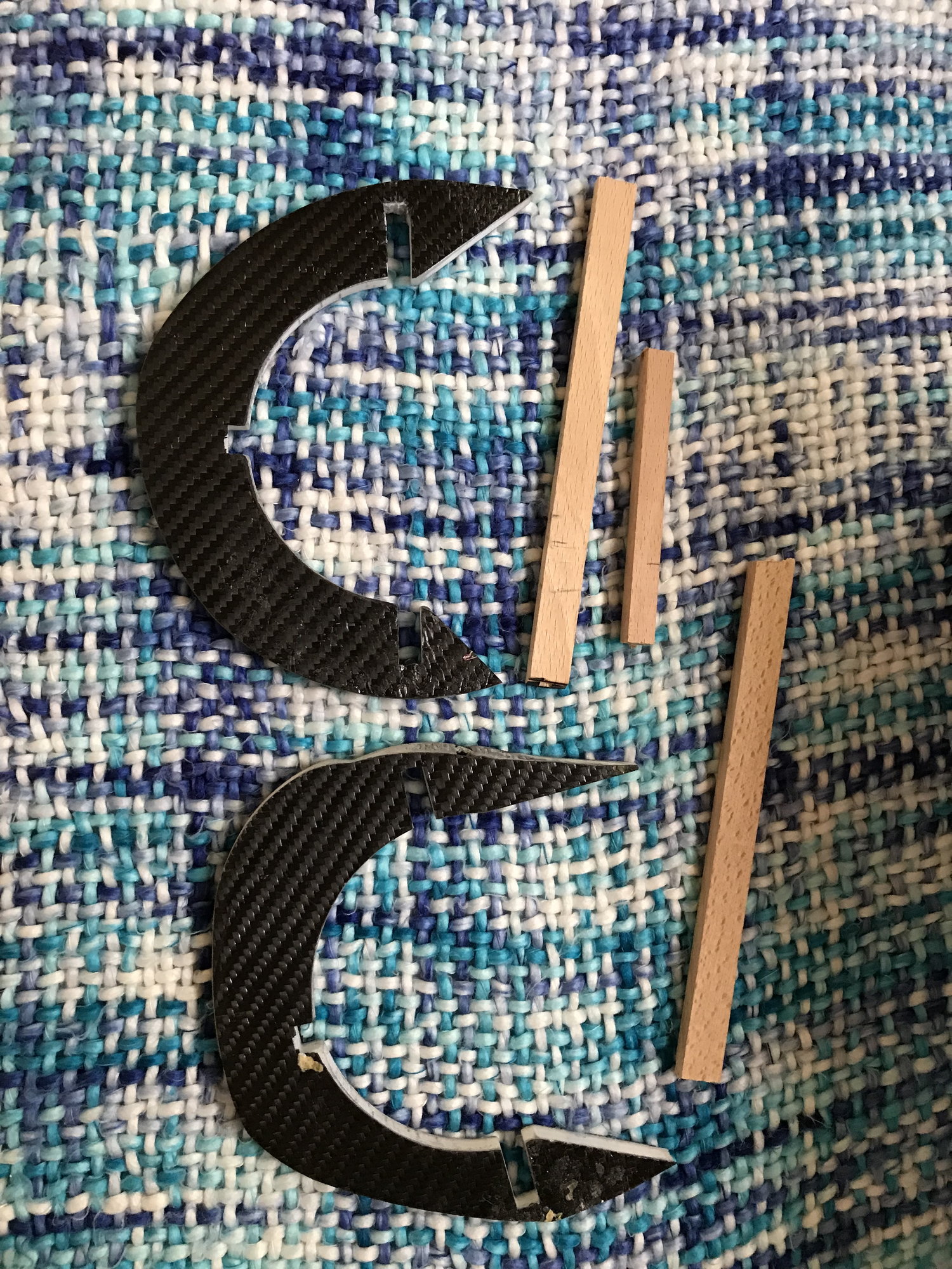
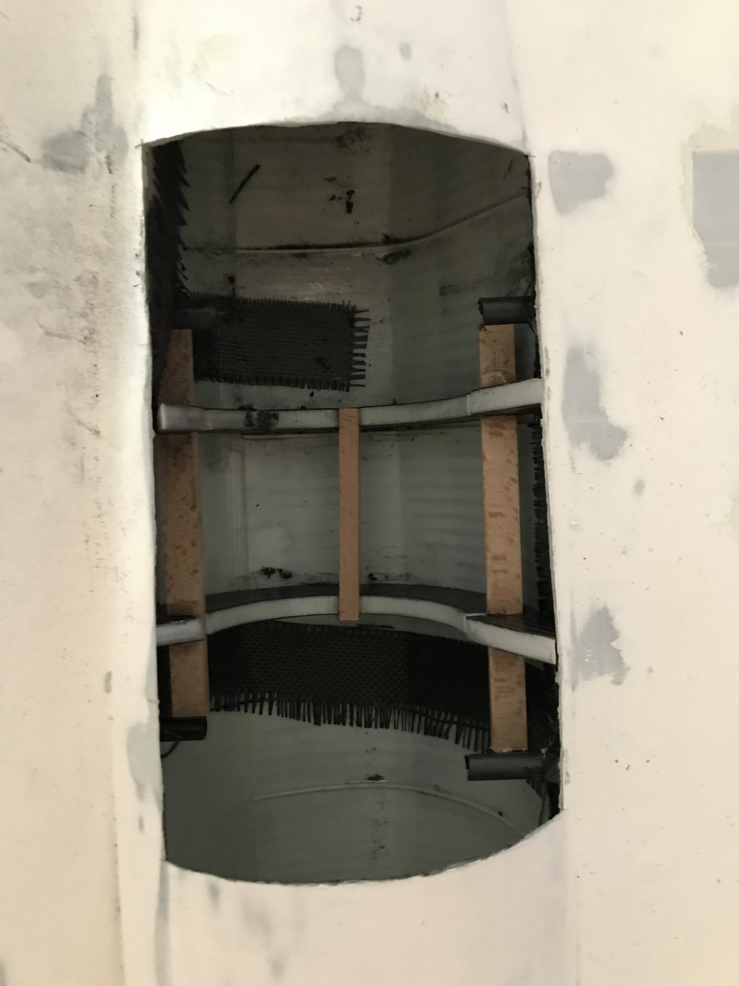
After printing and glueing the parts, I made some structural reinforcements. I used down-sized wing profile of my carf J10's wing. Cut 6 mm plywood according to this pofile and laminated one side of it with carbon-fiber fabric. These are glued to their places with epoxy (with long time curing). Made some holes on them and body. Inserted 10 mm carbon tubes from one wing site to the other. At later times, I cut and omitted some part of them.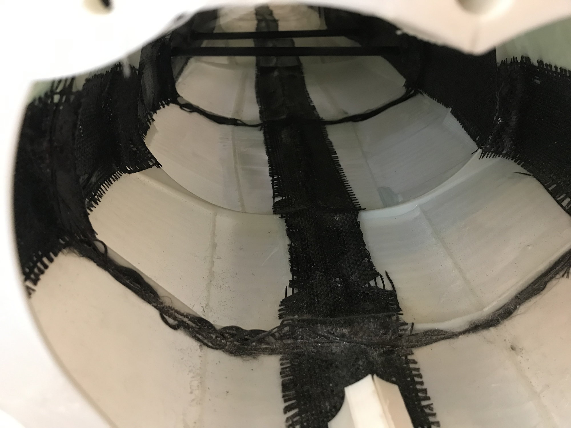
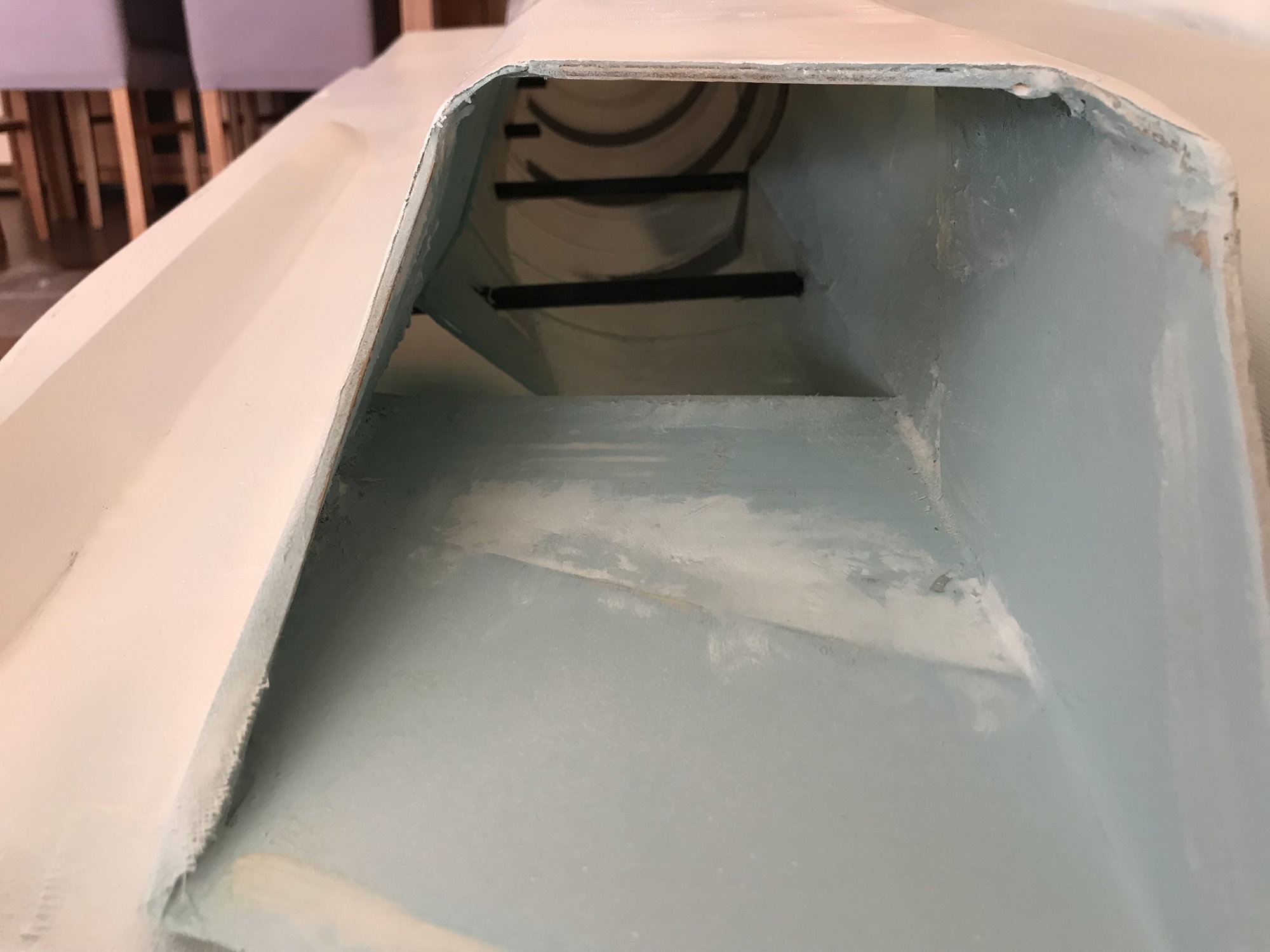
After printing and glueing the parts, I made some structural reinforcements. I used down-sized wing profile of my carf J10's wing. Cut 6 mm plywood according to this pofile and laminated one side of it with carbon-fiber fabric. These are glued to their places with epoxy (with long time curing). Made some holes on them and body. Inserted 10 mm carbon tubes from one wing site to the other. At later times, I cut and omitted some part of them.
 10-16-2019, 08:37 PM
#22
Thread Starter

SANDING and Lamination
Again I am writing; YOU CAN NOT IMAGINE HOW HARD TO SAND PLA+. Maybe someone knows an easy way of it. I tried direct sanding; filling with some lightweight fillers than sanding, priming at first and after sanding, laminate with glass fabric and sanding. I can say that no one is better than the other. I never used and tried electrical devices since the heat they generated would make more irregularites on the surface.
So I can say that print quality and glueing the parts are very important. By the way, flexibility of this thin plastic walls could affect sanding results, printing not lengthy ones on z axis would decrease flexibility.
In order to cover with glass-fabric, I used 120 gram/sqm one and lamination epoxy (written on it 160; I don't know it is important or not).
And after dry, I primed all the surfaces since sanding again could disturb lamination.
Last edited by Selcuk; 10-16-2019 at 08:41 PM.
10-16-2019, 09:34 PM
#23
Thread Starter
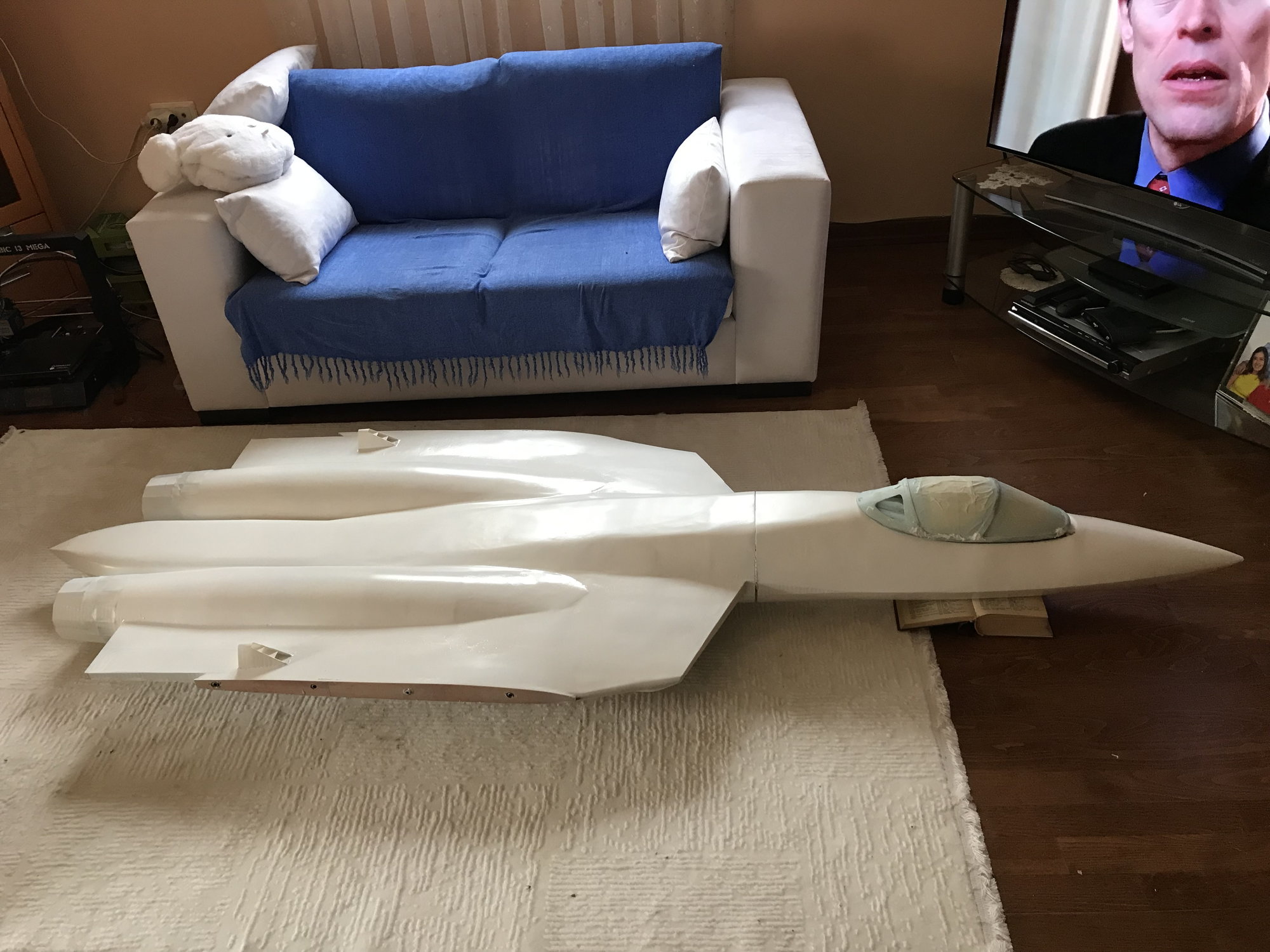
I have used 3 kilograms of PLA+ for all body printing. 5 kg used for all Project. However I can guess that about 1 kg went to trash. The body was about 9 kg before placement of reinforcements,turbines,electronics,etc. Before maiden only the body was 17 kg.
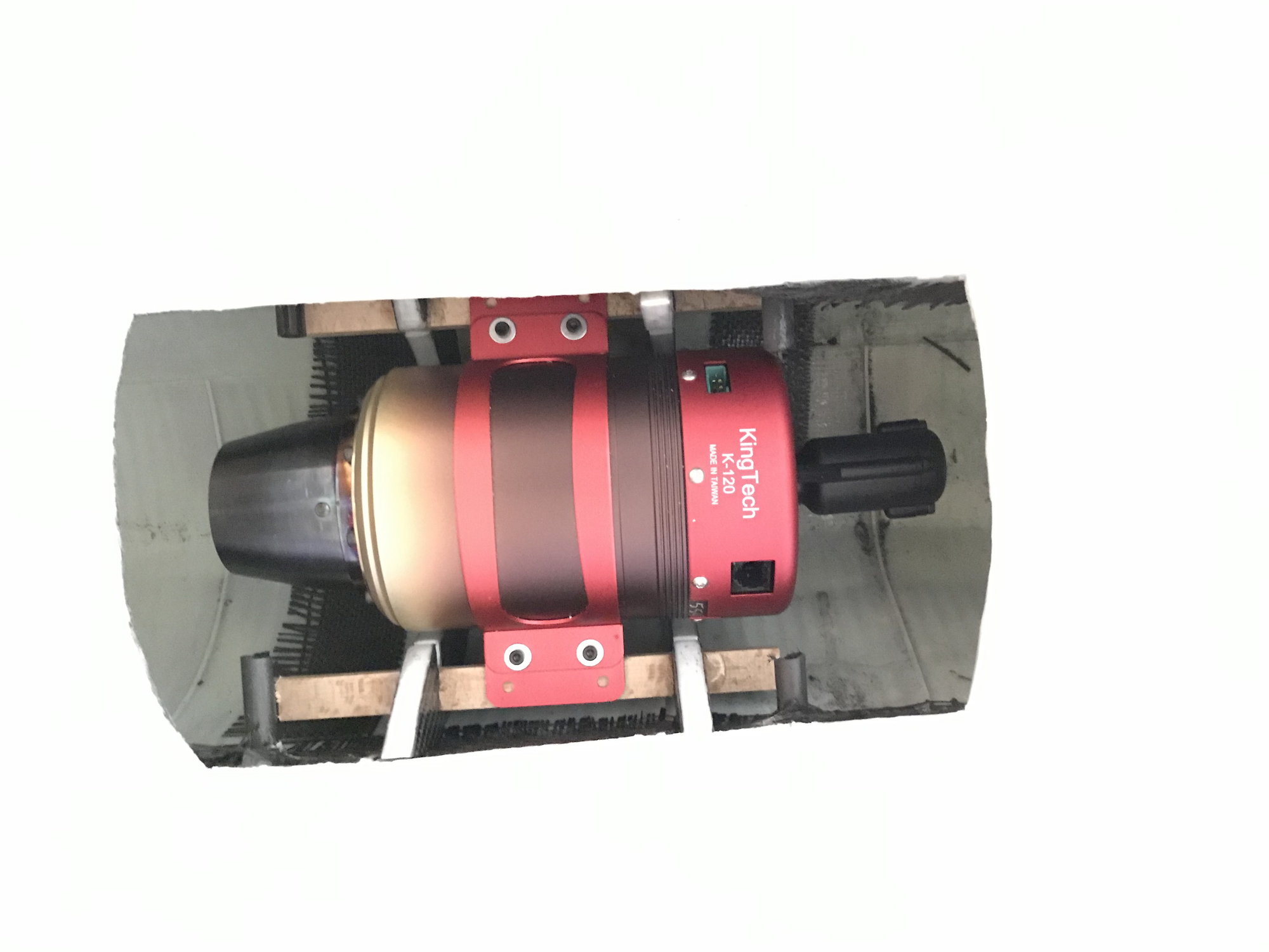
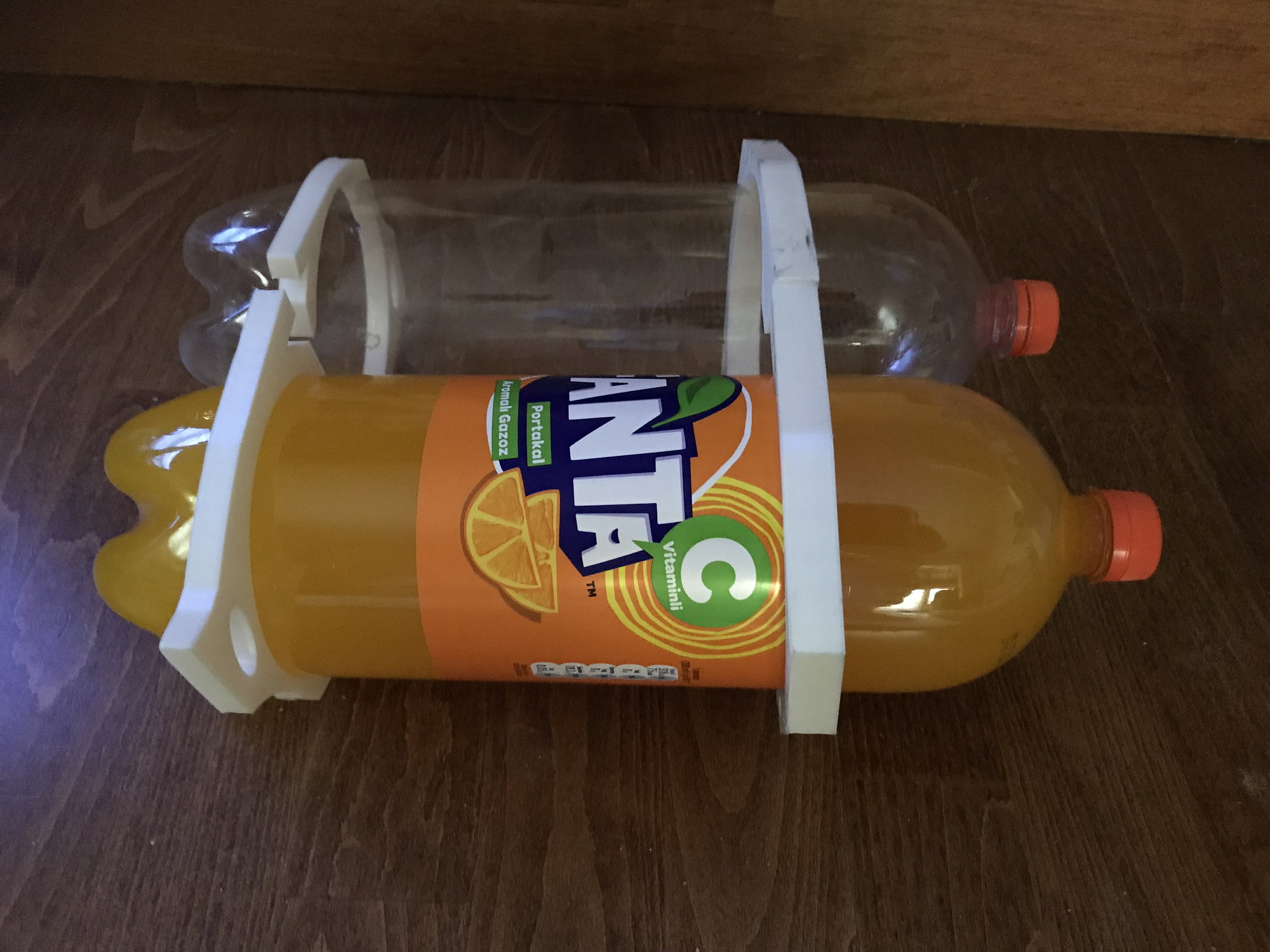
Printed the front flaps with 10 percent infill. Printed the turbine carriers with 35 percent infill and laminated both sites with carbon-fiber fabric. They were placed by cutting the before placed carbon fiber tubes in contuinity with the remaining parts. 2.5 liters of soda bottles were used for main tanks and their carriers printed 35 percent infill.
10-16-2019, 10:55 PM
#24
Thread Starter
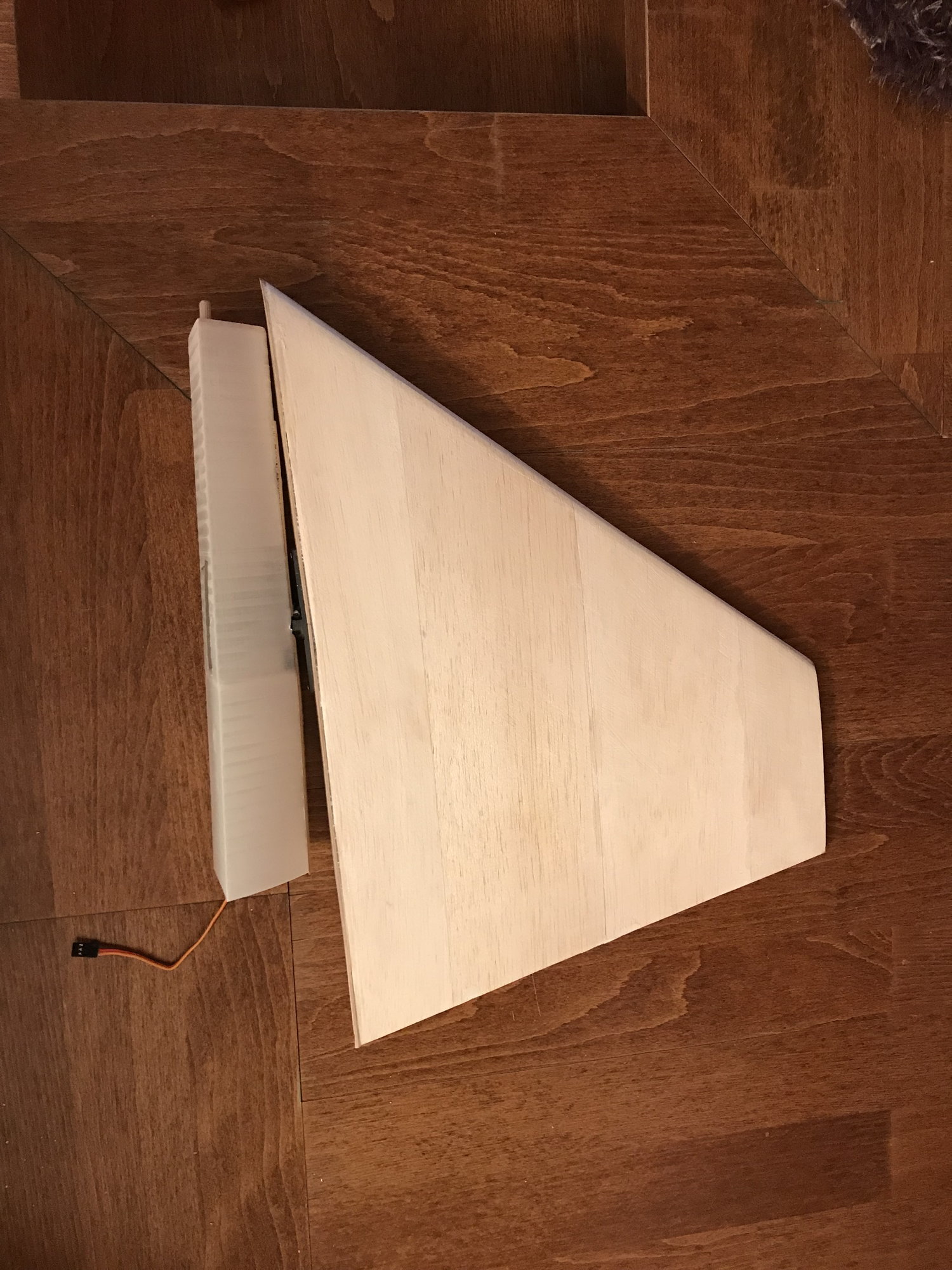
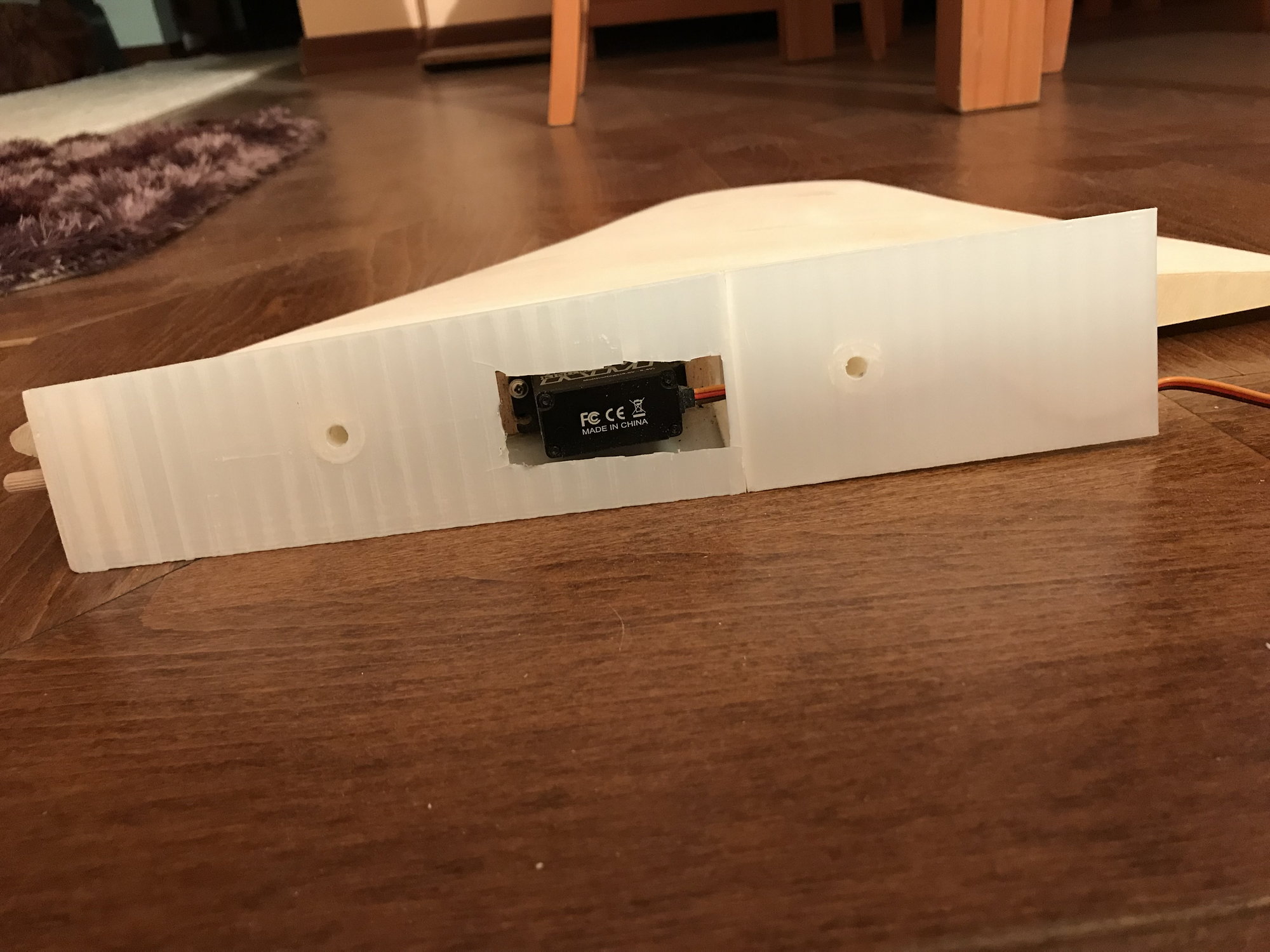
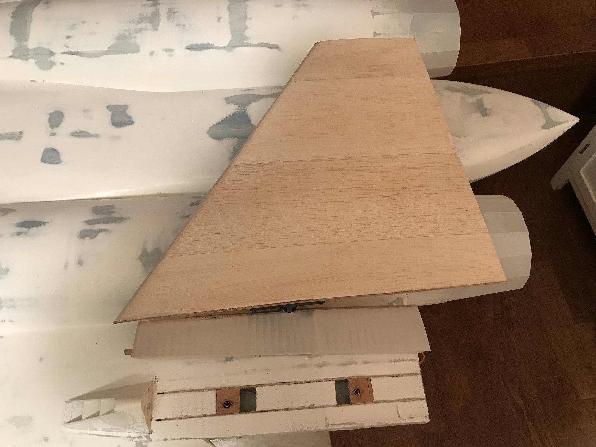
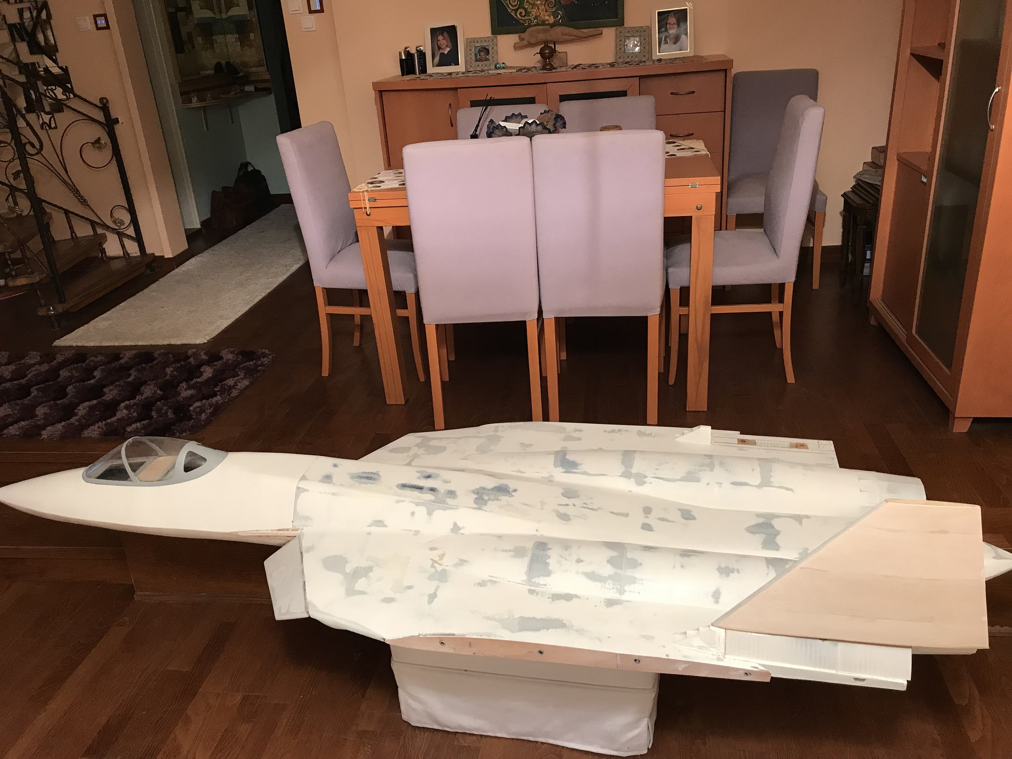

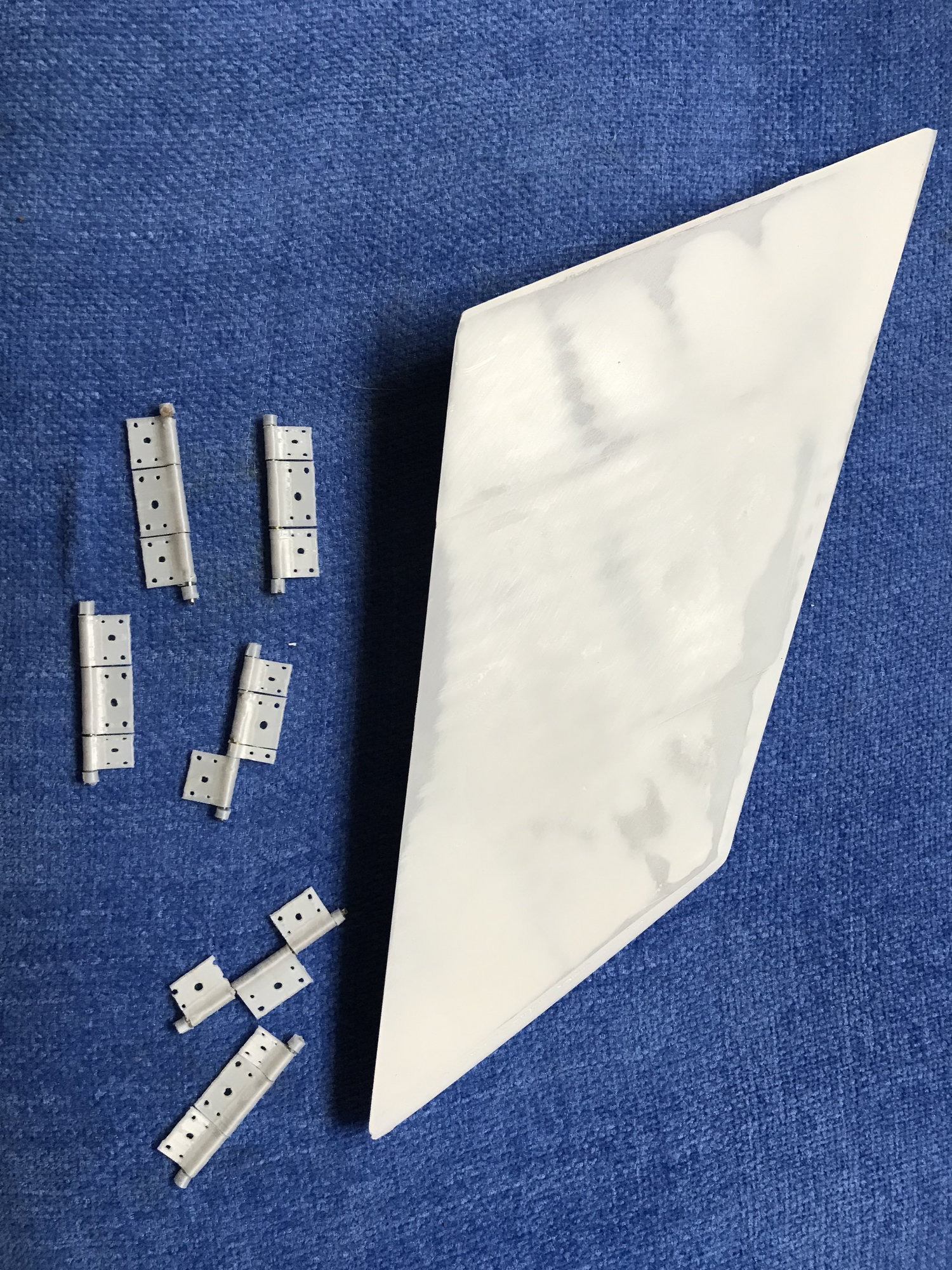
Rudders
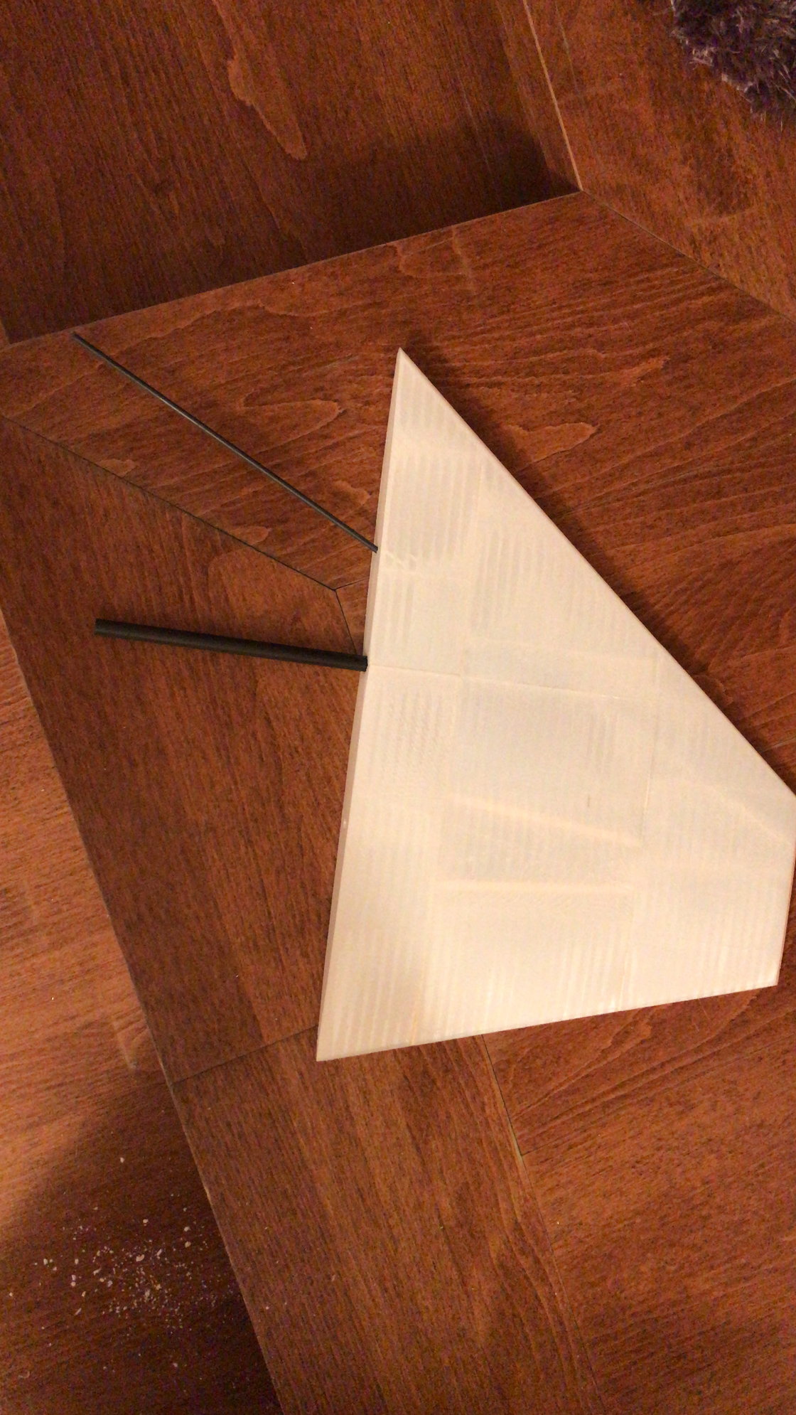
I printed the rudders with some spars but without infill. Placed 2 carbon sticks inside it. But there were to much waves on it, so took away the walls and covered them with balsa sheets of 2mm. Then glass covered and painted.
Printed the carrier of rudders. Laminated externally and reinforced internally. Put a 30 kg metal geared with double ball-bearings servo inside it. Aluminium servo arms were screwed under rudders. So the rudders are directly on top of servos. This type of connection created some discussion between my friends. I only tried to put servo at mean aerodynamic cord. After maiden they are still alive. Each rudder trays connected with body by the way of long 6 mm screws. And these trays cover servos of elevators. Rudders angles are not at scale angle now. I will increase it a little bit more for the second flight.
PS. If you have an experience about direct connection with servo and a moving surface please write your comments.
10-17-2019, 06:50 AM
#25
If you search, you will find a lot of good info on “full moving stabs” here. The AMA even has some documentation on where to put the pivot point. As a general rule, 25-30% of the Mean Aerodynamic Cord has been an accepted safety spot.
There is also ALOT of debate regarding static balancing of full moving horizontal stabilizers. I have never balanced any full moving stabs, and I’ve had a few.
There is also ALOT of debate regarding static balancing of full moving horizontal stabilizers. I have never balanced any full moving stabs, and I’ve had a few.