


CARF Rebel MAX - Build Thread
 10-25-2021, 06:26 AM
#1

Thread Starter
My Feedback: (1)

I think this thread will finally complete the entire series of CARF Rebels that are out there. I've seen the Hot, the Classic, and the Pro but nothing specifically for the Rebel MAX. So, I've decided to start one and slightly prompted by AEROSHELDON . My guess is he will probably have plenty of corrections for me and will probably guide me along the way.
Please note, I am a slow assembler so I'll just apologize now for that. I say assembler and not builder because this aircraft is very complete out of the container. In reality, all you have to do is install your servos, hook up your push rods, install the tanks and the rest of your avionics, bolt in the retracts, and, finally, install the thrust tube and turbine. I think, however, there are enough nuances that, for those of us who are more the pilot than the builder, maybe this will help all of us and "us" does include me.
Let's start off with that fact that this jet is freaking HUGE!! 11' long and a 10' wingspan. I ordered it from CARF and was lucky enough to get the last one on this shipment with the Infinity Scheme. That's the only scheme I was interested in and, while I would have preferred a color swap on the scheme, was very blessed to be able to land it. At the time of this writing, we are going through a shipping crisis. 40' containers that once cost a few thousand dollars to get from Thailand to the US now is costing 20 thousand. So far, Andreas (owner of CARF) has absorbed the cost and hasn't raised shipping but there is no way they could stay in business if he continued to do so. IMHO, he should and will raise the cost of shipping (not the aircraft) soon. This is why I took this Infinity Max that hasn't been claimed yet. I had also spoken to my rep and he told me that if I ordered a color swap, the factory would easily have it done within 1 1/2 months but to get it shipped could easily take another 4-6 months. I don't blame the factory for this, it's just the predicament we're in at the moment. While I whole-heartedly believe it's worth the wait, I don't wanna.
The plane comes in 3 big containers/boxes. The aircraft was very well protected and not a mark was found on inspection. I've seen a few posters show pictures of their Rebel's that had transferred some of the wrapping paper "markings" onto their paint jobs so when I picked up the plane, I was a little nervous about it. At least with mine, this was not the case and the airplane had some nice thin foam around all the parts and then packed with foam, bubble wrap, etc. around that. The wings, HStabs, and VStabs were all packed in their bags and were in perfect shape. Once the assembly is completed, I'll buff out the paint and any tiny blemishes that are there will be gone. This is just a beautiful jet, y'all.
The thrust tube for the turbine is listed as an "accessory" and must be purchased separately as well as the OEM 5 Liter fuel tank. Wait, 5 liters? Really? Y'all, that's 1.3 gallons that you're carrying around per flight (assuming you fill it up of course). At 6.75 lbs./ gallon using Jet A, that's roughly 9 lbs. of added weight just in fuel. I mean, wow! We'll see how much fuel I burn per flight but for me and the fact I've never owned something quite this big, that's just unreal for a model. As far as the thrust tube goes, that came separately as did the fuel tank from the jet, itself. The thrust tube is a master piece. Dual-walled at the back half of the tube and a carbon fiber bell mouth. Again, not a mark on it. The fuel tank is also very light and made out of fiberglass. It comes with the vent hole at the top and the fuel bung in the center of the side. It also has a very cool baffle in the middle of the tank to keep 1.3 gallons of fuel from sloshing around. All this to say, they've thought of everything and the quality of work is amazing throughout. I haven't weighed any components yet and, to be honest, probably won't until the aircraft is complete and ready for CG checks but every single component of this jet from CARF is ridiculously light for its size yet feels structurally strong.
Another component that must be purchased separately are the retracts. I've purchased the Electron ER50evo retracts with the GS-200 controller. I did buy them from CARF so that I know it is the set that they "expect" for the assembly. These are not cheap but are, by far, the best on the market. They also arrived separately but, again, are perfect and Electron has definitely built a good product. I know, I'm preaching to the choir here but dang.
I'll list my components here and will update this post (hoping this becomes a popular thread) at the bottom with all of my settings once we get this thing completed. I'm expecting this plane to come in around 19 kilograms (42 pounds) prior to fuel based on what I've seen from a few others and on YouTube so better news is this airplane should be able to compete/fly without an LMA waiver from the AMA. I bought this plane to compete in F3S Jet Aerobatics and....I like big airplanes. While the Rebel Pro isn't all that much smaller, the light wing loading on the MAX makes for some amazing slow flight characteristics and bigger just simply looks more amazing. It "looks" like it's flying so much slower if for no other reason than the size of it. Sort of like a 747 on approach to land. It looks like it's about to stall but, in reality, is still moving right along at 160-180 kts. I can't wait to finish this thing. I have all the components now so the only thing it's going to take is time which, unfortunately, I don't have a lot of but I vow to keep this thread up to date as I go.
Here are my components:
I'll take some more pictures this evening and update this post in the morning. Again, this is more about the assembly process and a place to put all of my experience so others can learn or criticize. I'm sure I'll learn some things from y'all through this process. I just ask that we treat each other with respect.

My wife is 5'2" and this thing is two of my wife! The fuselage does come apart in 3 sections. The rear section is just in front of the vertical stab and actually houses the thrust tube independently. It makes it very easy for this plane to come apart. This section is approx. 3'. The main part of the fuse is 7' long and the top canopy takes up the whole thing which makes the inside very accessible. This is true on all of the Rebel sizes. The nose cone is approx. 12" long.
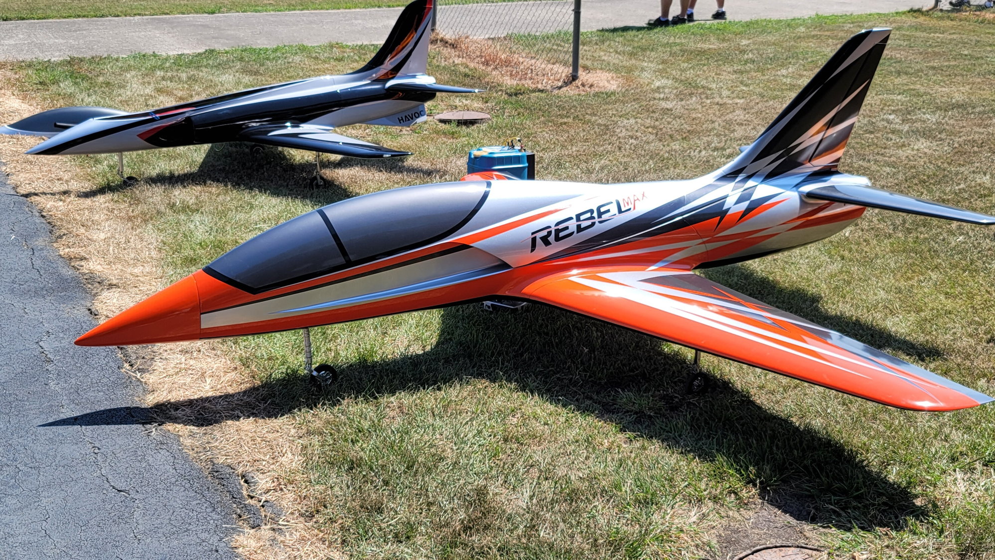
This is my buddy, John's, Rebel Max. I was going to buy the Pro until I saw his. It's all his fault!
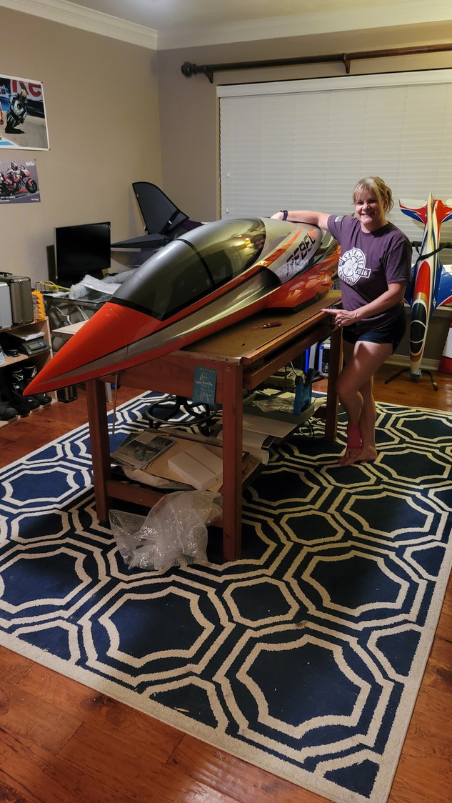
My wife is going to kill me for posting this but maybe she won't find this thread.
Please note, I am a slow assembler so I'll just apologize now for that. I say assembler and not builder because this aircraft is very complete out of the container. In reality, all you have to do is install your servos, hook up your push rods, install the tanks and the rest of your avionics, bolt in the retracts, and, finally, install the thrust tube and turbine. I think, however, there are enough nuances that, for those of us who are more the pilot than the builder, maybe this will help all of us and "us" does include me.
Let's start off with that fact that this jet is freaking HUGE!! 11' long and a 10' wingspan. I ordered it from CARF and was lucky enough to get the last one on this shipment with the Infinity Scheme. That's the only scheme I was interested in and, while I would have preferred a color swap on the scheme, was very blessed to be able to land it. At the time of this writing, we are going through a shipping crisis. 40' containers that once cost a few thousand dollars to get from Thailand to the US now is costing 20 thousand. So far, Andreas (owner of CARF) has absorbed the cost and hasn't raised shipping but there is no way they could stay in business if he continued to do so. IMHO, he should and will raise the cost of shipping (not the aircraft) soon. This is why I took this Infinity Max that hasn't been claimed yet. I had also spoken to my rep and he told me that if I ordered a color swap, the factory would easily have it done within 1 1/2 months but to get it shipped could easily take another 4-6 months. I don't blame the factory for this, it's just the predicament we're in at the moment. While I whole-heartedly believe it's worth the wait, I don't wanna.
The plane comes in 3 big containers/boxes. The aircraft was very well protected and not a mark was found on inspection. I've seen a few posters show pictures of their Rebel's that had transferred some of the wrapping paper "markings" onto their paint jobs so when I picked up the plane, I was a little nervous about it. At least with mine, this was not the case and the airplane had some nice thin foam around all the parts and then packed with foam, bubble wrap, etc. around that. The wings, HStabs, and VStabs were all packed in their bags and were in perfect shape. Once the assembly is completed, I'll buff out the paint and any tiny blemishes that are there will be gone. This is just a beautiful jet, y'all.
The thrust tube for the turbine is listed as an "accessory" and must be purchased separately as well as the OEM 5 Liter fuel tank. Wait, 5 liters? Really? Y'all, that's 1.3 gallons that you're carrying around per flight (assuming you fill it up of course). At 6.75 lbs./ gallon using Jet A, that's roughly 9 lbs. of added weight just in fuel. I mean, wow! We'll see how much fuel I burn per flight but for me and the fact I've never owned something quite this big, that's just unreal for a model. As far as the thrust tube goes, that came separately as did the fuel tank from the jet, itself. The thrust tube is a master piece. Dual-walled at the back half of the tube and a carbon fiber bell mouth. Again, not a mark on it. The fuel tank is also very light and made out of fiberglass. It comes with the vent hole at the top and the fuel bung in the center of the side. It also has a very cool baffle in the middle of the tank to keep 1.3 gallons of fuel from sloshing around. All this to say, they've thought of everything and the quality of work is amazing throughout. I haven't weighed any components yet and, to be honest, probably won't until the aircraft is complete and ready for CG checks but every single component of this jet from CARF is ridiculously light for its size yet feels structurally strong.
Another component that must be purchased separately are the retracts. I've purchased the Electron ER50evo retracts with the GS-200 controller. I did buy them from CARF so that I know it is the set that they "expect" for the assembly. These are not cheap but are, by far, the best on the market. They also arrived separately but, again, are perfect and Electron has definitely built a good product. I know, I'm preaching to the choir here but dang.
I'll list my components here and will update this post (hoping this becomes a popular thread) at the bottom with all of my settings once we get this thing completed. I'm expecting this plane to come in around 19 kilograms (42 pounds) prior to fuel based on what I've seen from a few others and on YouTube so better news is this airplane should be able to compete/fly without an LMA waiver from the AMA. I bought this plane to compete in F3S Jet Aerobatics and....I like big airplanes. While the Rebel Pro isn't all that much smaller, the light wing loading on the MAX makes for some amazing slow flight characteristics and bigger just simply looks more amazing. It "looks" like it's flying so much slower if for no other reason than the size of it. Sort of like a 747 on approach to land. It looks like it's about to stall but, in reality, is still moving right along at 160-180 kts. I can't wait to finish this thing. I have all the components now so the only thing it's going to take is time which, unfortunately, I don't have a lot of but I vow to keep this thread up to date as I go.
Here are my components:
- CARF Rebel MAX - Infinity Scheme
- Electron ER50evo Retracts from CARF w/ GS-200 controller
- Kingtech K235G4+ Turbine (CARF says this plane will fly on a 210-260. I spoke with a friend that flew this on a 260 and he thought is was too much power, at least for F3S. This bird is not meant to bore holes in the sky but perform aerobatics within a competition-sized flight box)
- PowerBox Mercury SRS Unit with iGyro and GPS sensor
- Futaba S9177SV servos QTY: 8 (2 Aileron, 2 Elevator, 2 Flap, 1 Rudder, 1 NG Steering)
- Futaba 7108RX QTY 2 for redundancy
- Futaba 32MZ Transmitter
- CARF OEM Thrust tube
- CARF OEM 5L Fuel Tank
- DigiTech 250ml UAT
I'll take some more pictures this evening and update this post in the morning. Again, this is more about the assembly process and a place to put all of my experience so others can learn or criticize. I'm sure I'll learn some things from y'all through this process. I just ask that we treat each other with respect.
My wife is 5'2" and this thing is two of my wife! The fuselage does come apart in 3 sections. The rear section is just in front of the vertical stab and actually houses the thrust tube independently. It makes it very easy for this plane to come apart. This section is approx. 3'. The main part of the fuse is 7' long and the top canopy takes up the whole thing which makes the inside very accessible. This is true on all of the Rebel sizes. The nose cone is approx. 12" long.
This is my buddy, John's, Rebel Max. I was going to buy the Pro until I saw his. It's all his fault!
My wife is going to kill me for posting this but maybe she won't find this thread.
Last edited by smcharg; 10-25-2021 at 08:27 AM.

The following 2 users liked this post by smcharg:
AEROSHELDON (10-25-2021),
Canadian Man (11-11-2021)
10-25-2021, 07:20 AM
#2
My Feedback: (4)
Max is definitely on my bucket list but have avoided it due to space issues. The Pro is more manageable for me, but the flight characteristics that I would want from this plane would mean I would still gaze longingly at the Max's floating effortlessly down the flightline.
Looking forward to your thread!
Tom M
Looking forward to your thread!
Tom M
 10-26-2021, 07:56 AM
#4
Thread Starter
My Feedback: (1)
Thanks guys! I've found my desire to keep this thread alive is forcing me to want to assemble quicker so.....that's something.
Last night, I took some pictures of the other components that were discussed in the beginning. Namely, the thrust tube and tank. Here are a few photos of those:
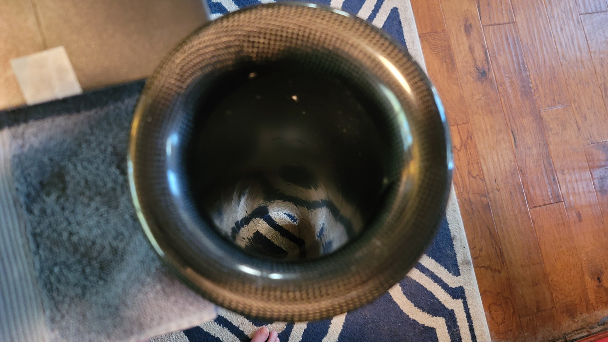
Carbon Fiber bellmouth. The nice part is that the top or front of the tube is almost against the lip of the bellmouth making it very easy to figure out distance to mount from the turbine.
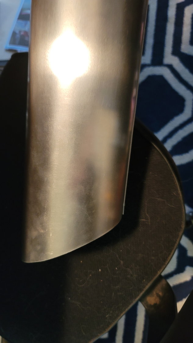
The back half of the tube is dual-walled. Construction is very nice and the pipe arrived without a single dent or scratch. I love the angled exhaust. The longer part is the top. Please excuse the stupid dog hair.
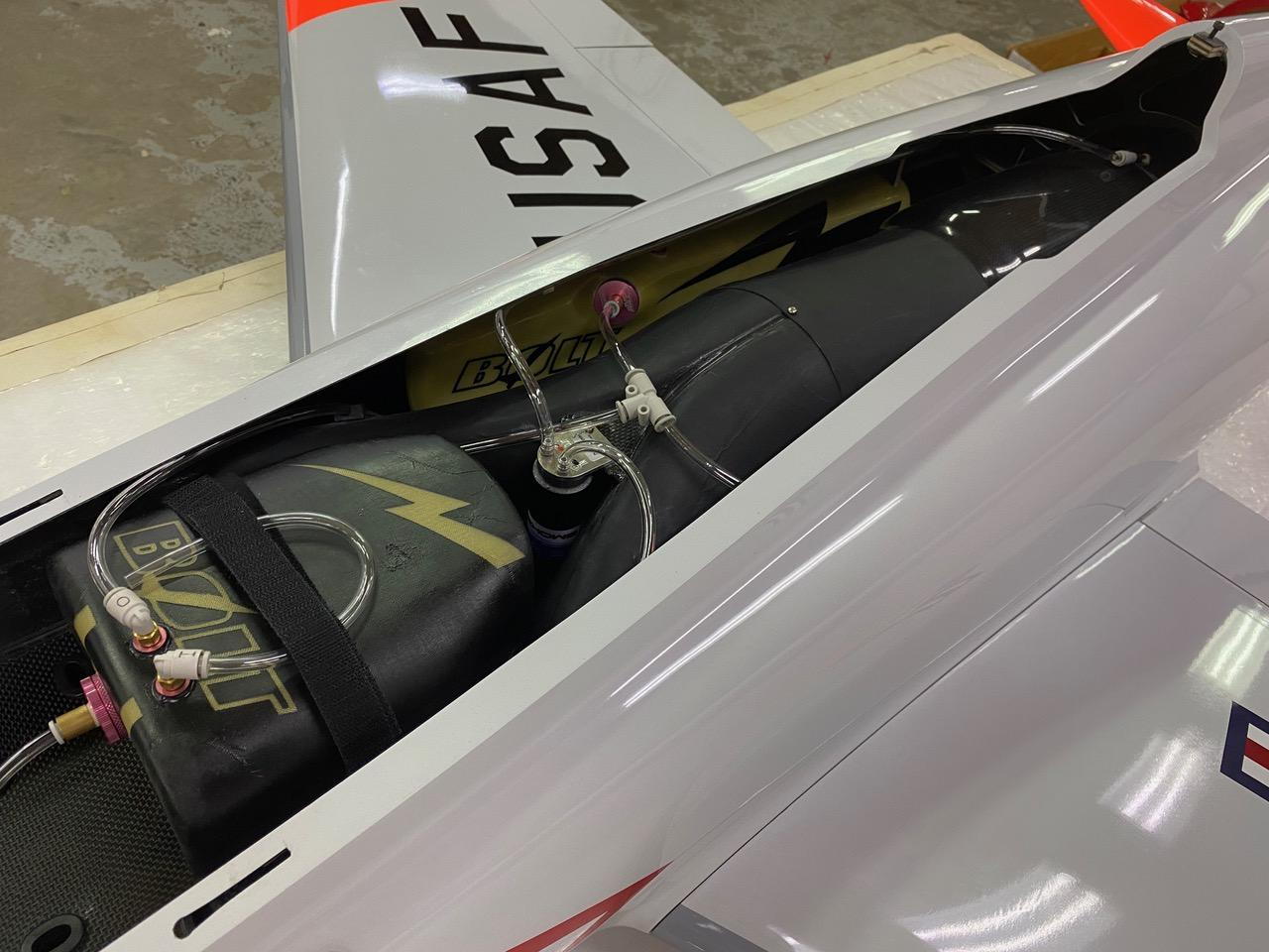
The OEM 5L fuel tank. It's made out of fiberglass and, while very lite, seems to be very strong. The vent nipple is at the top of the tank. I believe it is 6mm but I haven't assembled it yet.
OEM 5L tank showing fuel bung and vent. Note the middle of the tank where the "joint" is. This is an internal fuel baffle to keep the 1.3 gallons of fuel from sloshing around too much.
This is a view of the baffle inside the tank. It's not real clear but I think you'll get the idea. Pretty nice tank for sure!
Again, there's not really an instruction manual but I don't think any of us really expect one. CARF does include a nicely bound 3-4 page "Tips and Tricks" which gives us some clues on specific things that may not be clear in the build process. For example, they discuss the setup of the flap servos and specifically to set full flap setting such that the servo arm and control arm are as close to in-line as possible thus relieving the majority of torque required off the servo. In hindsight, this makes complete sense but I didn't really think of it that way.
I decided to start with the wings. The wing setup is fairly simple and very clean. There is a lot of room to work with in a plane this size and design. The aileron servo compartment cover is perfectly fit and the aileron servo hole is designed such that my Futaba 9177SV servos are a direct drop in. The retract holes are very clean as well and cut specifically for the Electron ER50eVo retracts that are also available from CARF (that way you make sure you get the right legs for the Max/Pro as they are the same). The gear plates are pre-drilled and installed for you. All you have to do is add the 6-32 blind nuts supplied and screw them in with the supplied bolts. Always use some Locktite on all the bolts when building. I know that seems obvious but it's not hard to forget so I'm saying it again.
Aileron servo bays ready to drop in servos the same size as the Futaba 9177SV. The cover (not displayed) fits perfectly with no gaps in the recessed area. Simply drill 4 pre-designated holes and screw it down
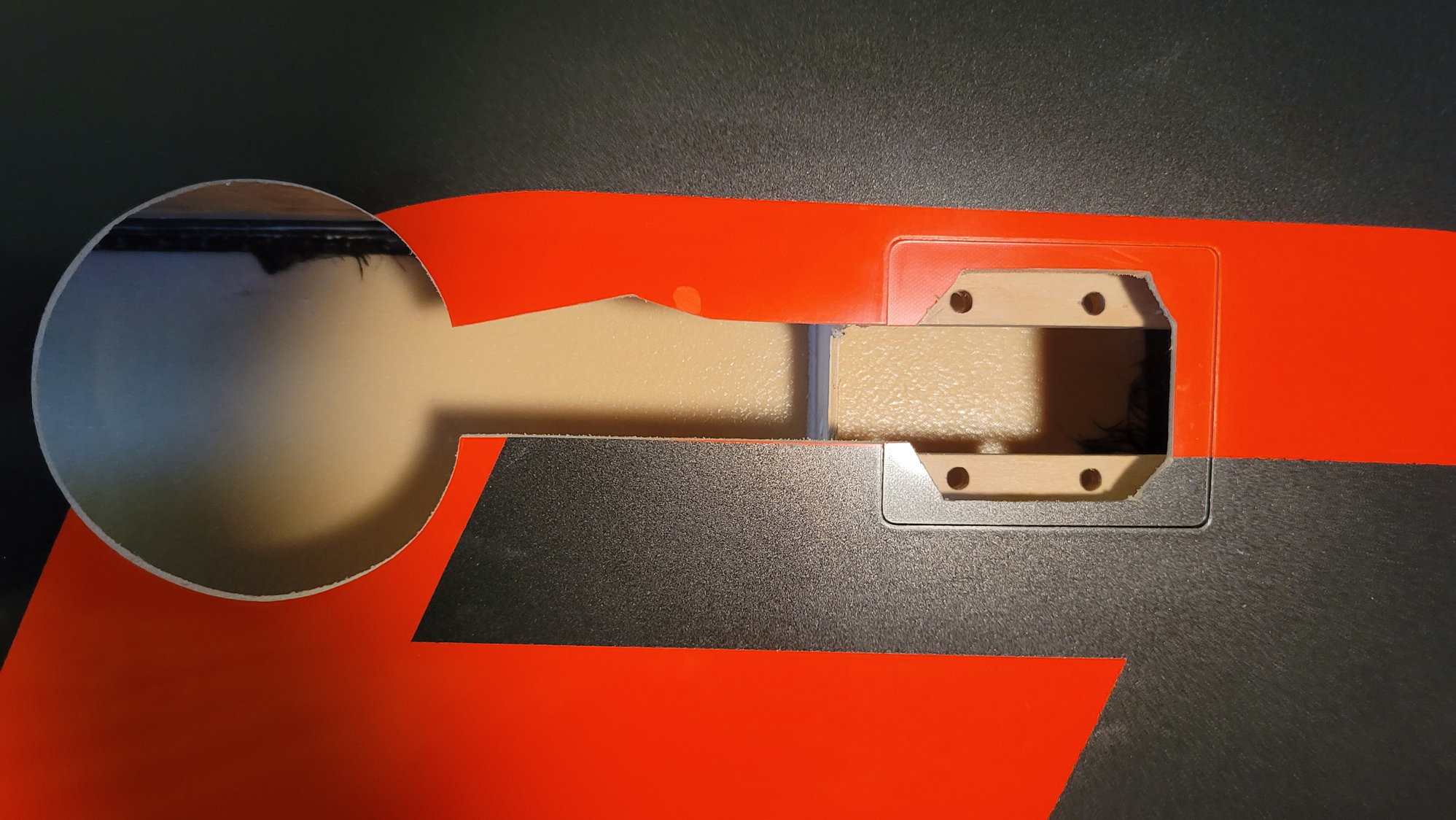
Retract bays with mounting block sans cover that goes over the mounting block. One could add gear leg covers if one chose to. I won't do this because matching that cutout is something I don't want to tackle.
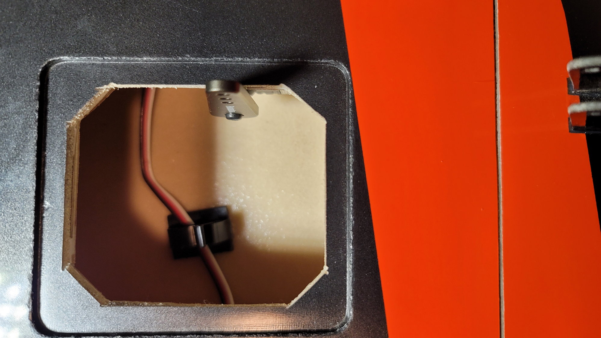
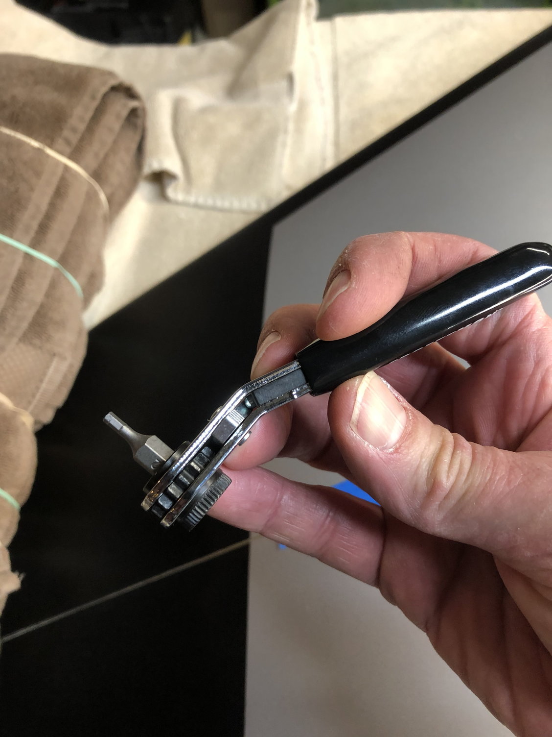
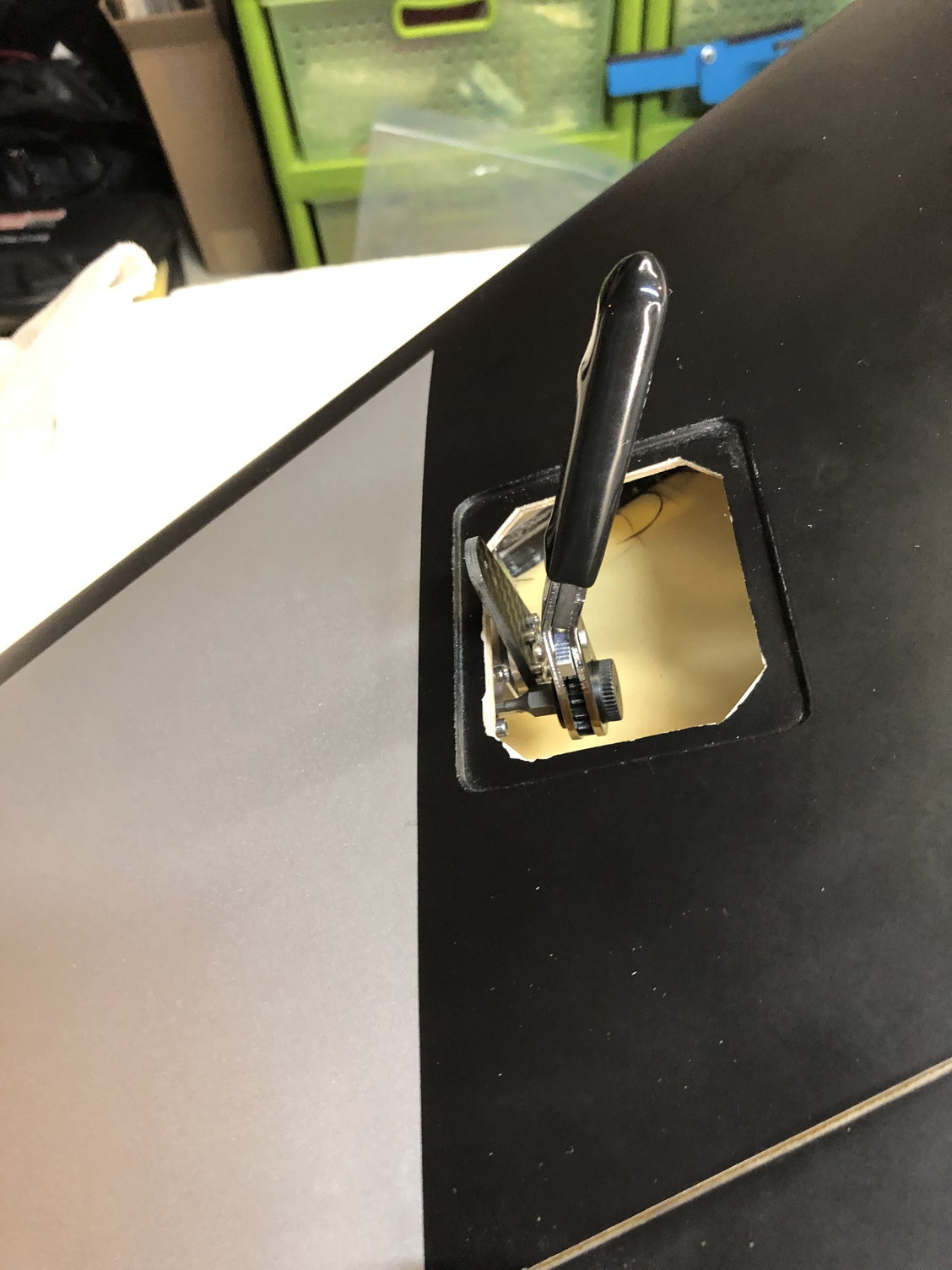
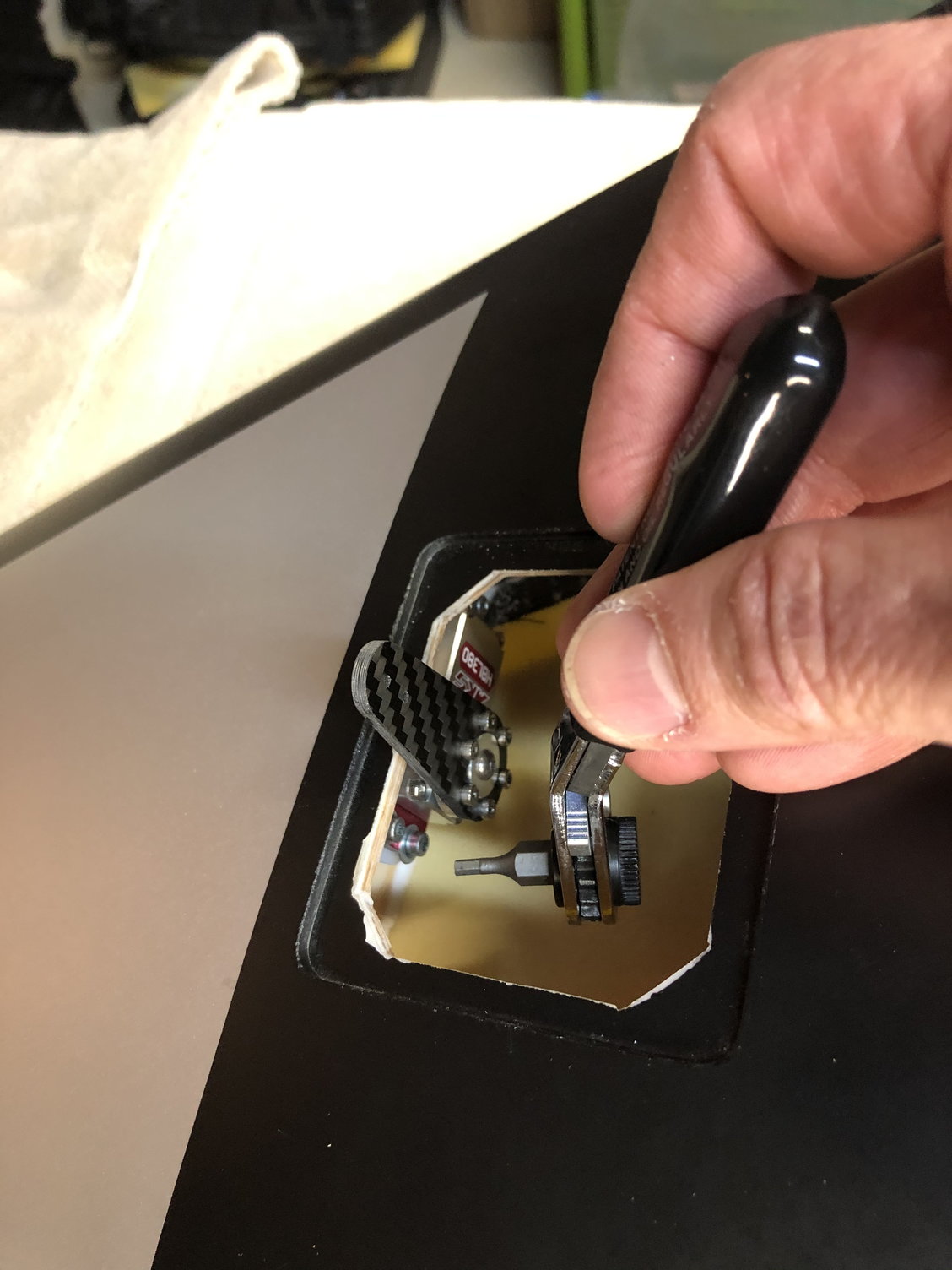
I will say this; Getting to the back aileron servo screws (nearest the trailing edge) is not easy. I'm sure some of you have developed a tool to get to these but us that have not and have sausage fingers, this is a frustrating feat. Luckily, I got a "Dad tool" for Christmas one year that is essentially a snake extension for a screwdriver. I was able to go through the wheel well and get to those screw heads to tighten them up. The front screws were no problem. This tool will also make it fairly easy to get to the flap servo mounting block but, if you haven't installed your retract yet, it'd be easy enough to access the flap servo from the open retract bay. I used a 38mm servo arm from Futaba for 25 tooth servos. It's longer than I needed but it looks good and longer isn't necessarily a bad thing. I may find out this is problematic if I can't get enough throw out of the servo but, I'll cross that bridge if I need to later on. The cover for the aileron is certainly modifiable if you need to grind out a little bit. For me, the servo arm and servos were simply drop-in....which I like.
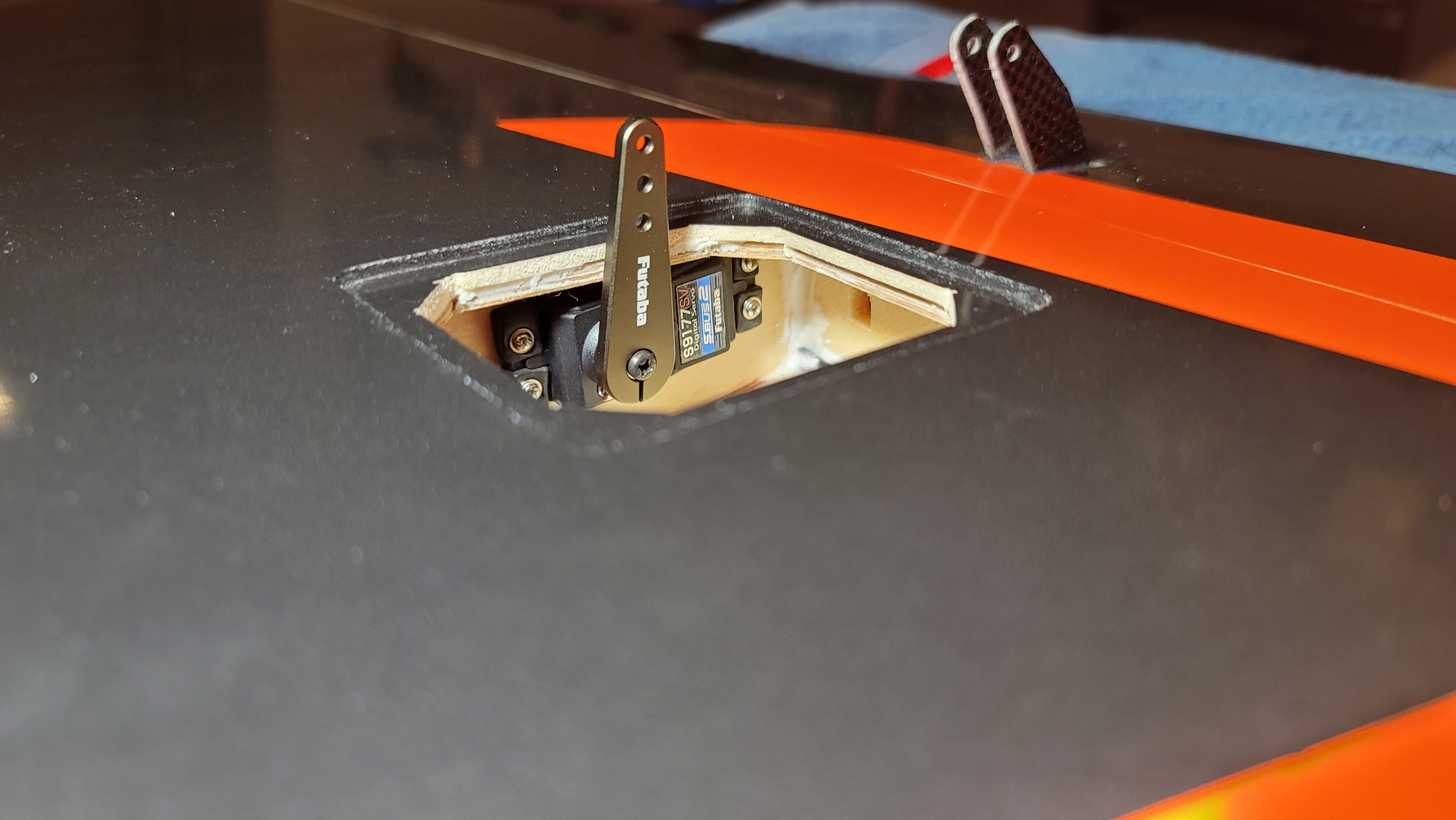
38mm servo arms on the aileron servo. The servo screws at the trailing edge are interesting to get to.
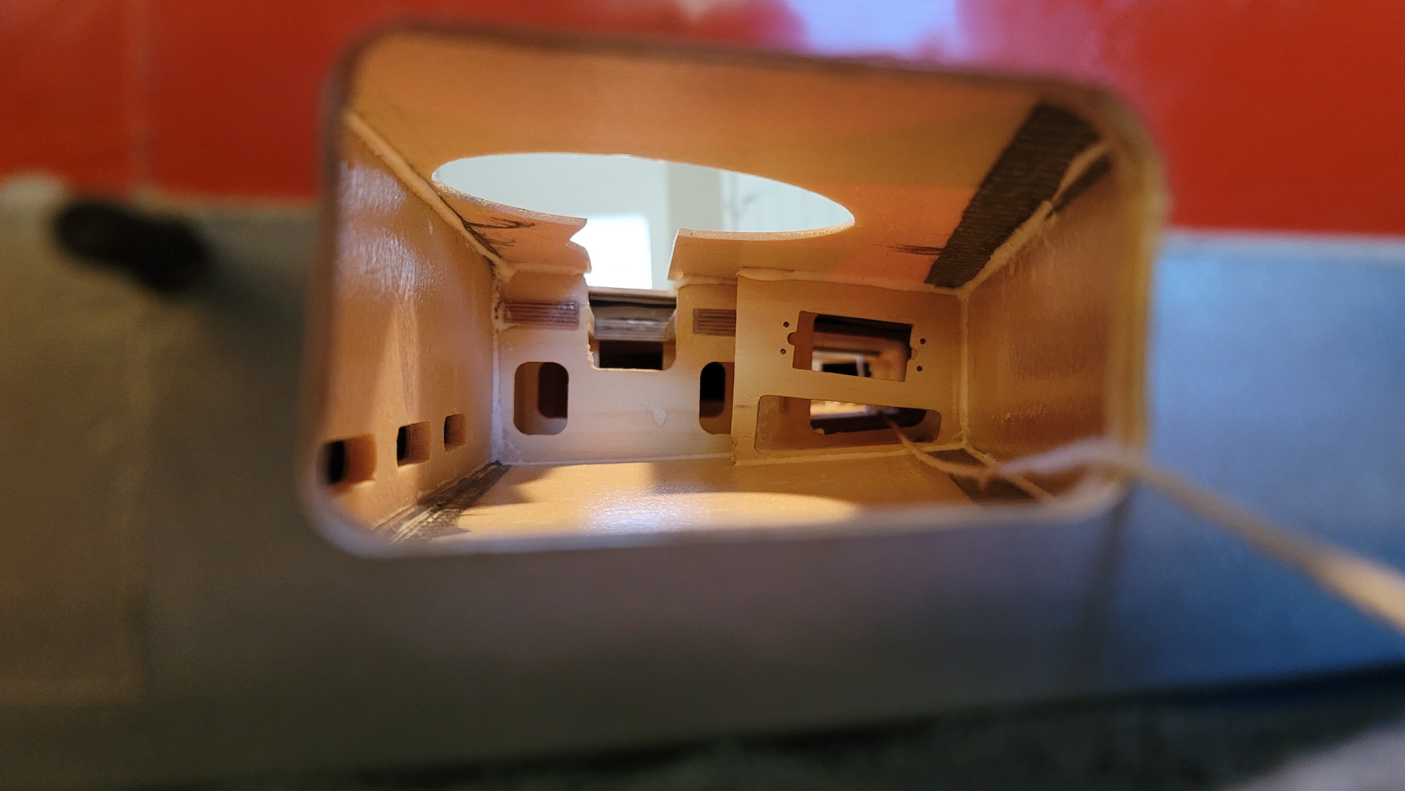
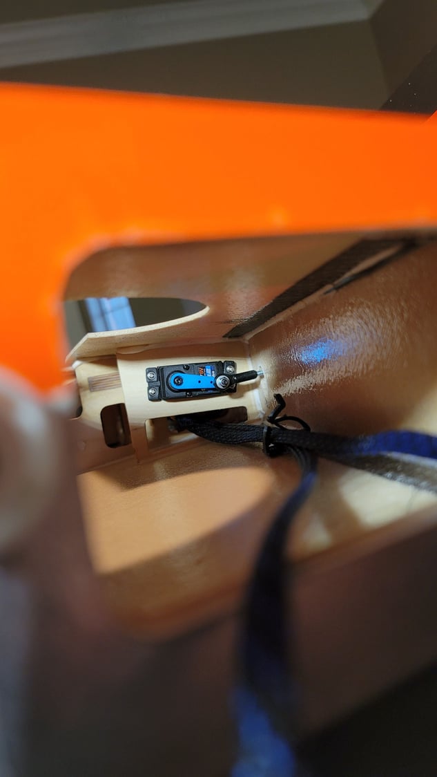
This is looking at the root rib inside the wing at the trailing edge. You'll see the flap servo mount there. The string hanging out is just my pull string for the aileron servo wire. I tied a nut to it and it took 10 seconds to feed it through from the aileron servo bay. Plenty of room!
The aileron servo wire run is fairly long. I decided to buy some PowerBox MAXI cable due to its properties, specifically, the ability to diminish voltage drop across long runs. I didn't want to cut off the end of the servo wire connections, however, because I want it to be an easy swap should I ever have to change servos out in the future. So, I used the female end of an extension and soldered it on to the MAXI wire. Then, I found a braided sleeve that I bought on Amazon that is abrasion resistant and is expandable. I bought the 1/4" stuff and it works perfectly. While I probably don't need it, I want to make this look as neat as possible and the fact this stuff weighs nothing made the decision for me. I also found some clips that I can use to run multiple wires through. My plan is to use an AMP 10-pin connector for each wing to connect it to the fuse. I bought those at Aero Panda. Pictures of these will come when I assemble them. So, I will run the aileron servo wire, flap servo wire, positive and negative wire for the Electron retracts and then the pos. and neg. wires for the brakes through these clips and then tie them all into the AMP connectors.
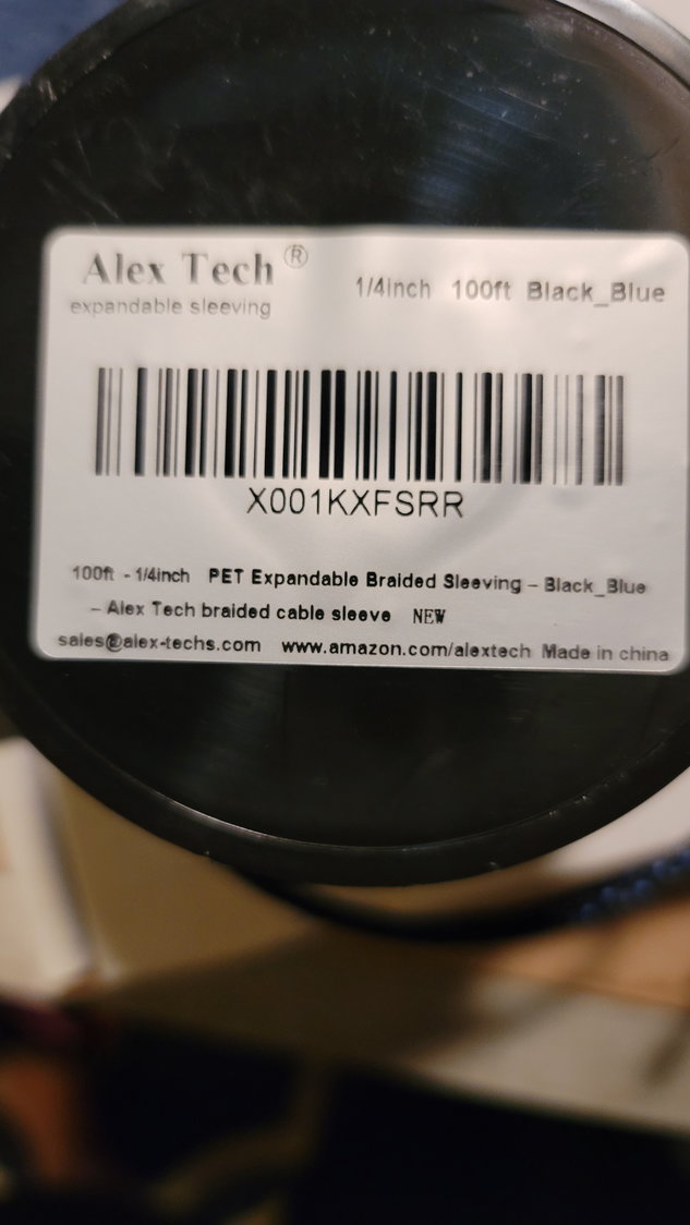
Braided sleeve from Amazon
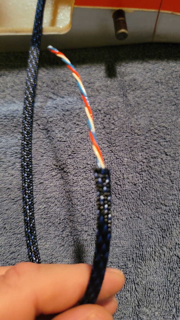
You have to work the wire through the sleeve but it's pretty easy.
Aileron servo wire now fed through the wing with the braided sleeve
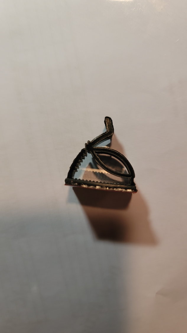
These are the clips, also bought from Amazon. I used some stuff called "Amazing Goop Max", also from Amazon, to glue them in even though they do have sticky pads.
This is the clip I'll use to bring the retract, flap, and aileron wire through to the root rib and then use the AMP connector to make the fuse/wing connection. It also makes sure that wires don't get in the way of the retracts.
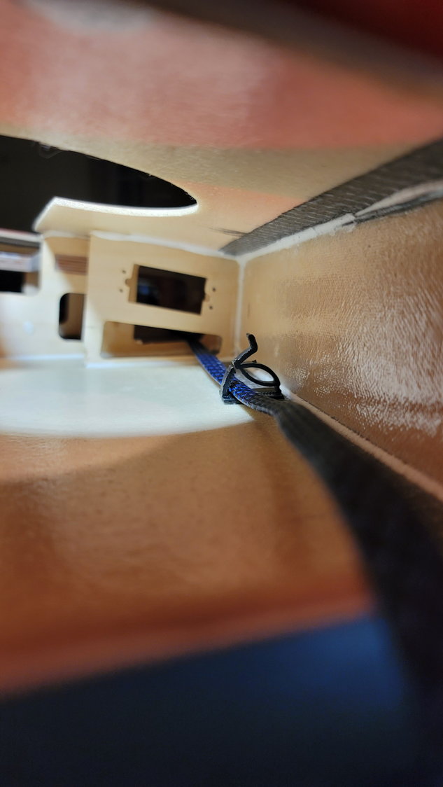
One more clip for the aileron servo wire to relieve any strain on the soldered cable. Plus, it keeps everything in place.
That's all I have for today. I'll try to get the flap servos mounted and hooked up this week and get some good pictures. It's still high school football/band season and both seem to be heading to state finals. I have to be the good dad and want to be so I'll update as soon as I can.
Last night, I took some pictures of the other components that were discussed in the beginning. Namely, the thrust tube and tank. Here are a few photos of those:
Carbon Fiber bellmouth. The nice part is that the top or front of the tube is almost against the lip of the bellmouth making it very easy to figure out distance to mount from the turbine.
The back half of the tube is dual-walled. Construction is very nice and the pipe arrived without a single dent or scratch. I love the angled exhaust. The longer part is the top. Please excuse the stupid dog hair.
The OEM 5L fuel tank. It's made out of fiberglass and, while very lite, seems to be very strong. The vent nipple is at the top of the tank. I believe it is 6mm but I haven't assembled it yet.
OEM 5L tank showing fuel bung and vent. Note the middle of the tank where the "joint" is. This is an internal fuel baffle to keep the 1.3 gallons of fuel from sloshing around too much.
This is a view of the baffle inside the tank. It's not real clear but I think you'll get the idea. Pretty nice tank for sure!
Again, there's not really an instruction manual but I don't think any of us really expect one. CARF does include a nicely bound 3-4 page "Tips and Tricks" which gives us some clues on specific things that may not be clear in the build process. For example, they discuss the setup of the flap servos and specifically to set full flap setting such that the servo arm and control arm are as close to in-line as possible thus relieving the majority of torque required off the servo. In hindsight, this makes complete sense but I didn't really think of it that way.
I decided to start with the wings. The wing setup is fairly simple and very clean. There is a lot of room to work with in a plane this size and design. The aileron servo compartment cover is perfectly fit and the aileron servo hole is designed such that my Futaba 9177SV servos are a direct drop in. The retract holes are very clean as well and cut specifically for the Electron ER50eVo retracts that are also available from CARF (that way you make sure you get the right legs for the Max/Pro as they are the same). The gear plates are pre-drilled and installed for you. All you have to do is add the 6-32 blind nuts supplied and screw them in with the supplied bolts. Always use some Locktite on all the bolts when building. I know that seems obvious but it's not hard to forget so I'm saying it again.
Aileron servo bays ready to drop in servos the same size as the Futaba 9177SV. The cover (not displayed) fits perfectly with no gaps in the recessed area. Simply drill 4 pre-designated holes and screw it down
Retract bays with mounting block sans cover that goes over the mounting block. One could add gear leg covers if one chose to. I won't do this because matching that cutout is something I don't want to tackle.
I will say this; Getting to the back aileron servo screws (nearest the trailing edge) is not easy. I'm sure some of you have developed a tool to get to these but us that have not and have sausage fingers, this is a frustrating feat. Luckily, I got a "Dad tool" for Christmas one year that is essentially a snake extension for a screwdriver. I was able to go through the wheel well and get to those screw heads to tighten them up. The front screws were no problem. This tool will also make it fairly easy to get to the flap servo mounting block but, if you haven't installed your retract yet, it'd be easy enough to access the flap servo from the open retract bay. I used a 38mm servo arm from Futaba for 25 tooth servos. It's longer than I needed but it looks good and longer isn't necessarily a bad thing. I may find out this is problematic if I can't get enough throw out of the servo but, I'll cross that bridge if I need to later on. The cover for the aileron is certainly modifiable if you need to grind out a little bit. For me, the servo arm and servos were simply drop-in....which I like.
38mm servo arms on the aileron servo. The servo screws at the trailing edge are interesting to get to.
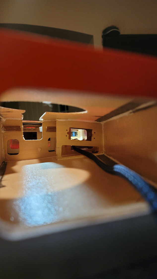
This is looking at the root rib inside the wing at the trailing edge. You'll see the flap servo mount there. The string hanging out is just my pull string for the aileron servo wire. I tied a nut to it and it took 10 seconds to feed it through from the aileron servo bay. Plenty of room!
The aileron servo wire run is fairly long. I decided to buy some PowerBox MAXI cable due to its properties, specifically, the ability to diminish voltage drop across long runs. I didn't want to cut off the end of the servo wire connections, however, because I want it to be an easy swap should I ever have to change servos out in the future. So, I used the female end of an extension and soldered it on to the MAXI wire. Then, I found a braided sleeve that I bought on Amazon that is abrasion resistant and is expandable. I bought the 1/4" stuff and it works perfectly. While I probably don't need it, I want to make this look as neat as possible and the fact this stuff weighs nothing made the decision for me. I also found some clips that I can use to run multiple wires through. My plan is to use an AMP 10-pin connector for each wing to connect it to the fuse. I bought those at Aero Panda. Pictures of these will come when I assemble them. So, I will run the aileron servo wire, flap servo wire, positive and negative wire for the Electron retracts and then the pos. and neg. wires for the brakes through these clips and then tie them all into the AMP connectors.
Braided sleeve from Amazon
You have to work the wire through the sleeve but it's pretty easy.
Aileron servo wire now fed through the wing with the braided sleeve
These are the clips, also bought from Amazon. I used some stuff called "Amazing Goop Max", also from Amazon, to glue them in even though they do have sticky pads.
This is the clip I'll use to bring the retract, flap, and aileron wire through to the root rib and then use the AMP connector to make the fuse/wing connection. It also makes sure that wires don't get in the way of the retracts.
One more clip for the aileron servo wire to relieve any strain on the soldered cable. Plus, it keeps everything in place.
That's all I have for today. I'll try to get the flap servos mounted and hooked up this week and get some good pictures. It's still high school football/band season and both seem to be heading to state finals. I have to be the good dad and want to be so I'll update as soon as I can.
Last edited by smcharg; 10-26-2021 at 08:26 AM.
 10-28-2021, 03:58 PM
#8
Thread Starter
My Feedback: (1)
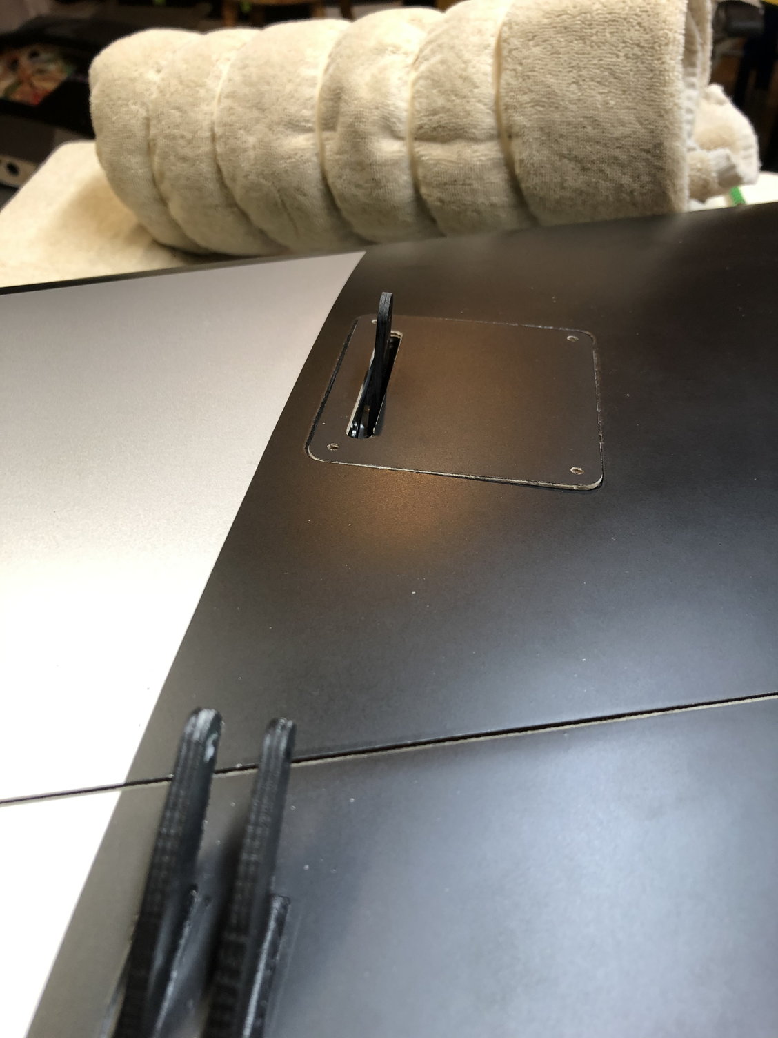
That's how the tank comes from the factory. It looks nothing like what's on the website.....thank goodness. I was ready to order one of Carlos' tanks (CM Jets) but I think this one is going to work perfect.
The following users liked this post:
AEROSHELDON (10-28-2021)
The following users liked this post:
bluelevel (01-08-2023)
 10-29-2021, 11:06 AM
#13
Thread Starter
My Feedback: (1)
Sheldon,
I'll confirm tonight for you. I just bought 8mm Vent/Taxi Tank connection and my UAT to Tank is also 8. I don't need it but, that's what I did so, I'll look at it tonight after the boy's football game.
I'll confirm tonight for you. I just bought 8mm Vent/Taxi Tank connection and my UAT to Tank is also 8. I don't need it but, that's what I did so, I'll look at it tonight after the boy's football game.
The following users liked this post:
AEROSHELDON (10-29-2021)
10-29-2021, 01:52 PM
#14
Thread Starter
My Feedback: (1)
Here's a picture of the plumbing that comes with the tank. I can confirm that all fittings are 6mm. The vent and the fuel outlet are festo and the inside of the fuel bung is nipple/tygon.
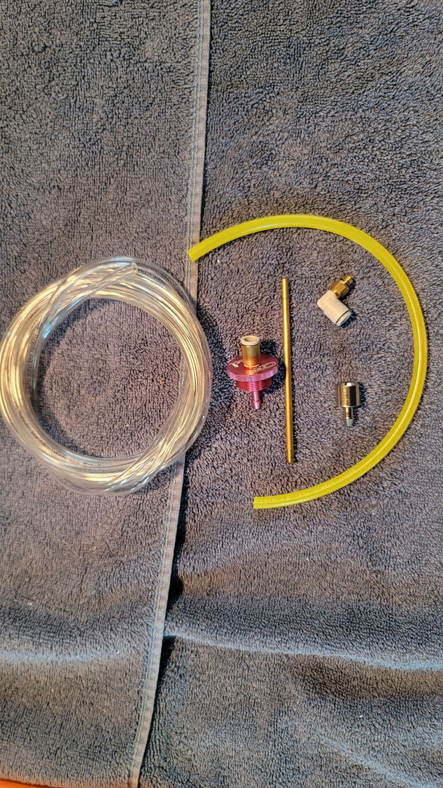
The tygon goes from inside the fuel bung onto the brass tube which will sit through the baffle and then another piece to the clunk behind the baffle. Very clean setup!
The tygon goes from inside the fuel bung onto the brass tube which will sit through the baffle and then another piece to the clunk behind the baffle. Very clean setup!
The following users liked this post:
AEROSHELDON (10-29-2021)
10-29-2021, 07:36 PM
#16
Thread Starter
My Feedback: (1)
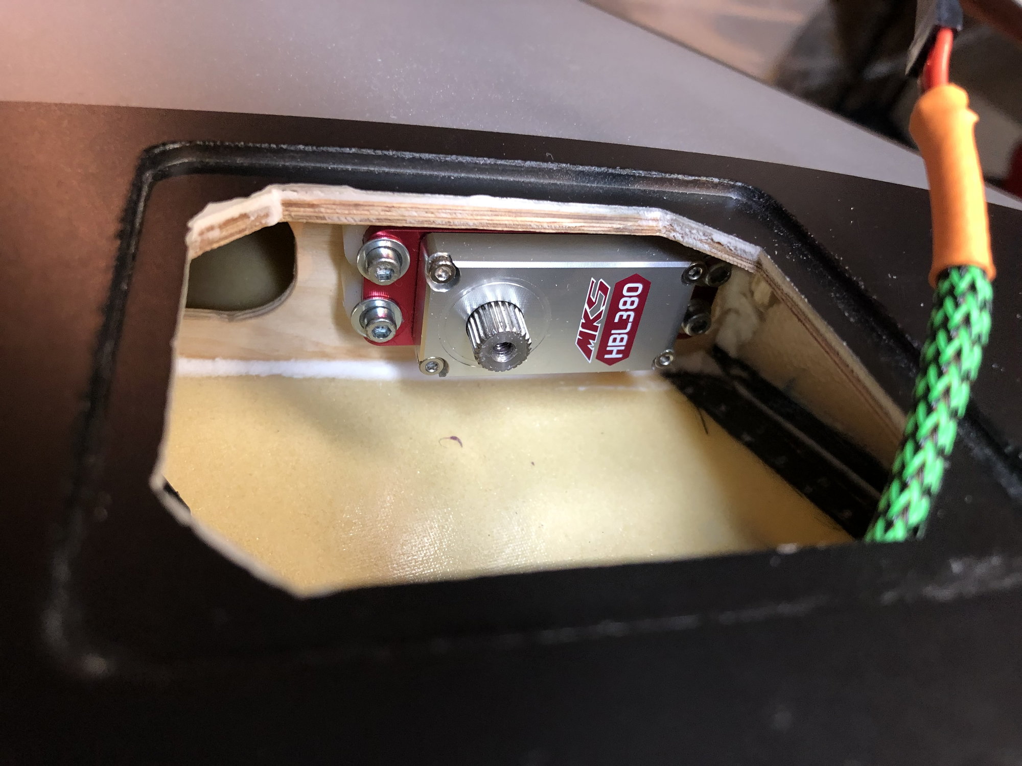
Flaps and ailerons are now done. Special thanks to my new friend Reever45 who gave me some excellent tips to get the linkage correct on the flaps. It's not bad once you understand but to set it right with the servo arm inline with the flap pushrod and getting enough travel is fun. Here's what I did:
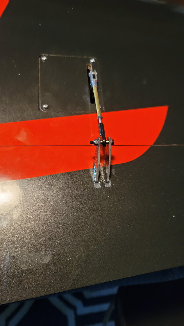
Aileron connections completed
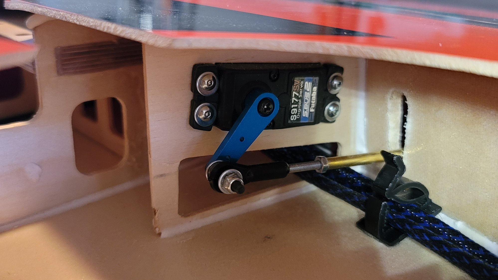
Servo arm and push rod as straight as I could get them. It's good enough to where when the servo is unpowered, it takes some physical force to get the flap retracted. Even if there is a little torque on the servo, it's greatly reduced
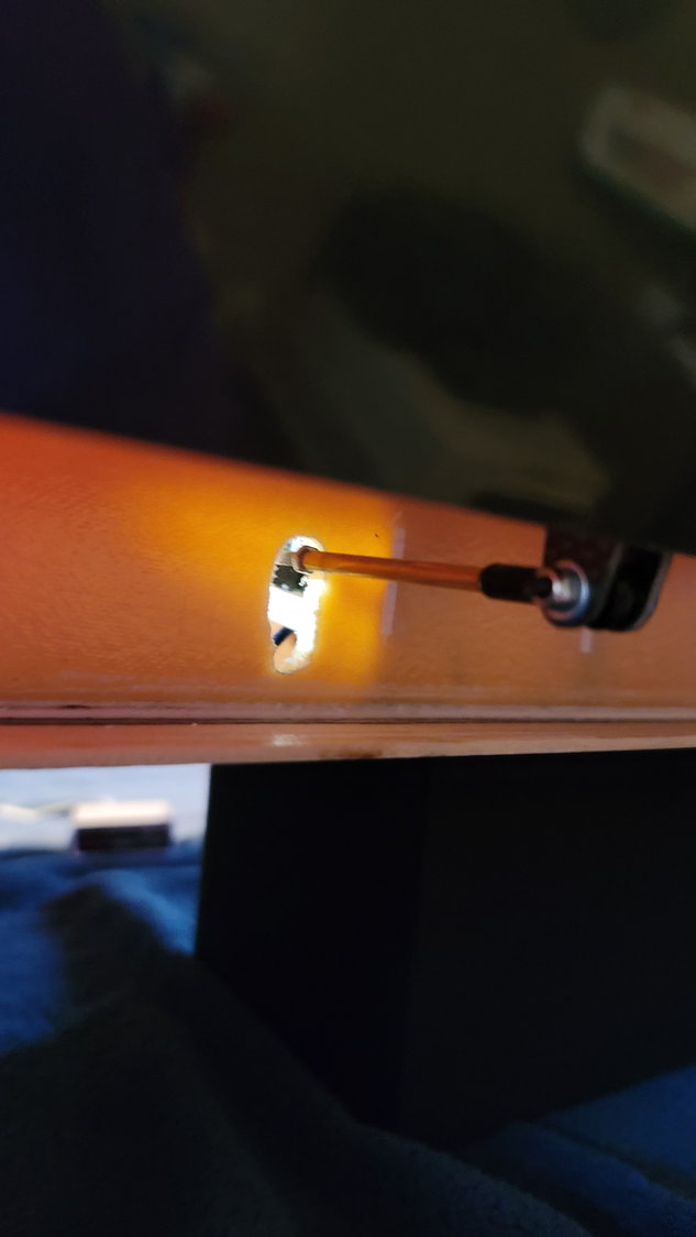
Pushrod clearance
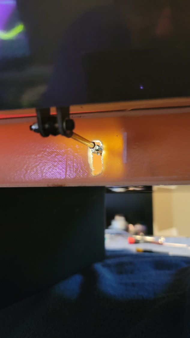
Pushrod clearance #2
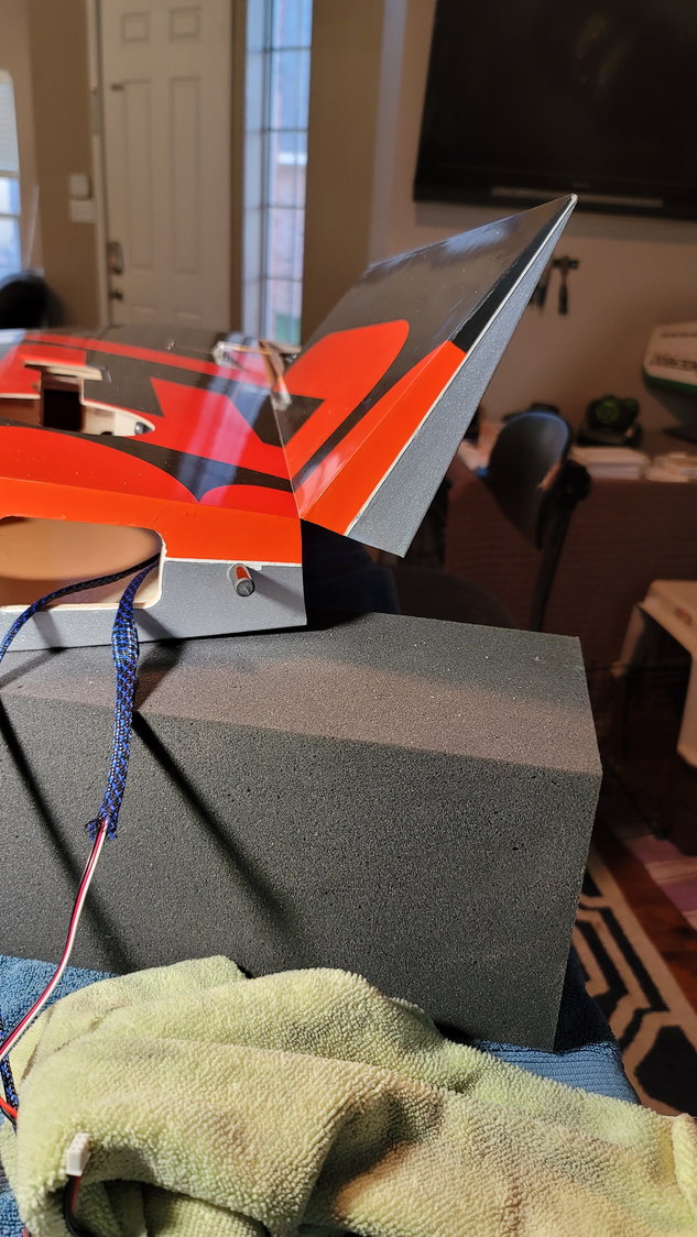
60 degrees of flap travel. These flaps are HUGE!
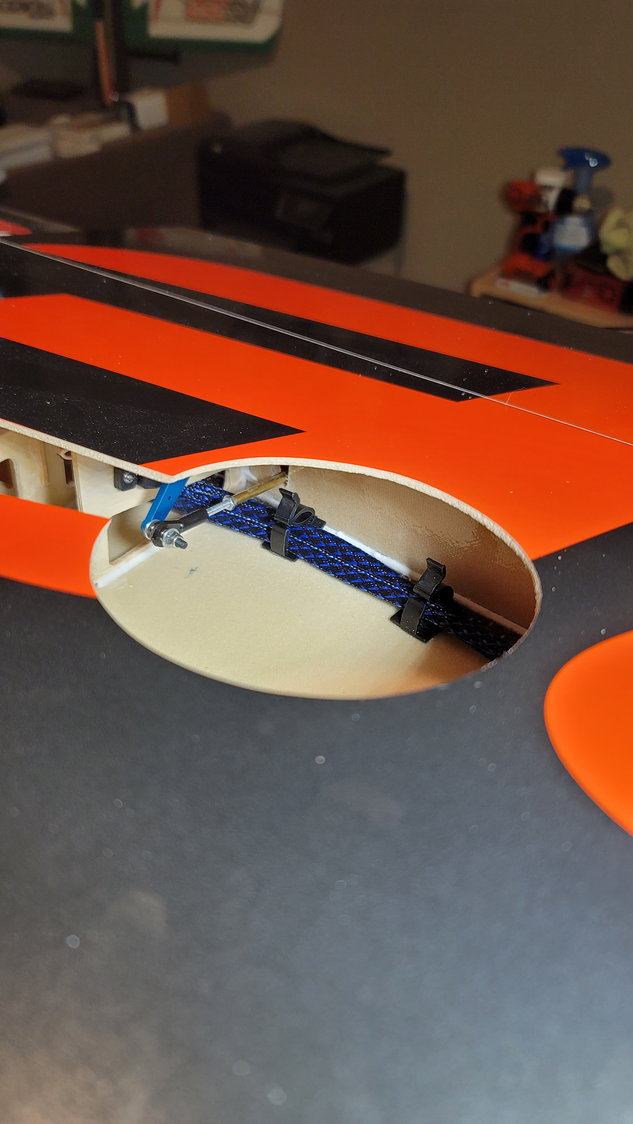
Cable holders in place and gooped in. This keeps them clear of the flap actuator
Finally, my last one made it into A&M today. I know, lots do but that's 3 of 4 that got into Texas A&M and this is one of the reasons I'm so dang slow in building. It's all worth it in the end.

The last of my four children just found out today that he made it in to Texas A&M and he's going to be auditioning for the Aggie band. In these parts, the Aggie band is something to behold. Proud Papa moment!
- There are two different lengths of threaded rod in the wing parts bag. I used the two short ones on the ailerons and the two long ones on the flaps
- There are two silver clevis connectors in that bag as well. I used those on the servo side of the ailerons and the supplied ball links on the control horn side.
- The supplied ball links were used on the flaps
- CARF recommends that you make sure to get the push rod of the flaps and the servo arm inline which eliminates torque on the servo with 60 degrees of flaps. This makes sense as these are BIG flaps. I used a 1" aluminum servo arm (in hindsight, an 1 1/4" may have been better but I made it work).
- Attach the pushrod to the servo arm and extend the servo arm so that it is inline with the push rod. Some folks did this a little different but I used just the supplied parts and screwed the ball links as far onto the threaded rod as I could and put the brass tube over that and tightened it against the control horn side. This length with the 1" arm was the perfect length to achieve 60 degrees of flap. If I had used an 1 1/4" arm, I would have cut the threaded rod so that it wasn't too long and that also would have worked. I did have to adjust the end points on the TX to 140% in order to get flaps fully up but, for flaps, that's fine and I'm not that worried about resolution issues.
- A decent amount of the trailing edge did have to be Dremeled out but it's a very soft foam-type trailing edge so it's definitely not structural. I considered adding some carbon fiber around that area and still may go back and do that but I'm really not worried about it.
Aileron connections completed
Servo arm and push rod as straight as I could get them. It's good enough to where when the servo is unpowered, it takes some physical force to get the flap retracted. Even if there is a little torque on the servo, it's greatly reduced
Pushrod clearance
Pushrod clearance #2
60 degrees of flap travel. These flaps are HUGE!
Cable holders in place and gooped in. This keeps them clear of the flap actuator
Finally, my last one made it into A&M today. I know, lots do but that's 3 of 4 that got into Texas A&M and this is one of the reasons I'm so dang slow in building.
It's all worth it in the end.The last of my four children just found out today that he made it in to Texas A&M and he's going to be auditioning for the Aggie band. In these parts, the Aggie band is something to behold. Proud Papa moment!
Last edited by smcharg; 10-29-2021 at 07:45 PM.
The following 3 users liked this post by smcharg:
10-29-2021, 08:02 PM
#18
Flap servo mounting screws. Are they std Futaba screws you have used? The kit should have had larger machine screws as CARF’s pre drilled holes are too large for most servo provided hardware
Dave.
Dave.
10-31-2021, 11:26 AM
#19
Thread Starter
My Feedback: (1)
Well-spotted, sir. Yes, those are the standard Futaba servo screws. They were just a place holder as, you're right, they would grab but not well. I was waiting for a shipment from RTL Fasteners for some #4 button-head screws. They arrived today and have been replaced now.
Note, if you're using the eyelets that come with Futaba screws, #4 and CARF servo screws are too big to use. I've decided to remove the eyelets but still use the rubber grommets and #4 screws. They are tight and provide the damping needed still. With a turbine, you typically don't have the vibration and I feel confident in this setup. Please, keep pointing out things wrong. I appreciate the backup and insights that I may not have.
 10-31-2021, 11:38 AM
#20
👍 yes Futaba never updated the mounting hardware when they went from 2kg servos to ‘70’kg Keep an eye on the 9177 on flap, they don’t tolerate load very long before burning out. Your full flap geometry should be OK.
Are the servo arms a known brand. They look a bit like some of the Amazon Chinese ‘Cheesaminium’ material arms. Some of those I can cut in half with side cutters! If they are soft they could bow under load.
Dave
Are the servo arms a known brand. They look a bit like some of the Amazon Chinese ‘Cheesaminium’ material arms. Some of those I can cut in half with side cutters! If they are soft they could bow under load.
Dave
10-31-2021, 12:21 PM
#21
Thread Starter
My Feedback: (1)
👍 yes Futaba never updated the mounting hardware when they went from 2kg servos to �70�kg Keep an eye on the 9177 on flap, they don�t tolerate load very long before burning out. Your full flap geometry should be OK.
Are the servo arms a known brand. They look a bit like some of the Amazon Chinese �Cheesaminium� material arms. Some of those I can cut in half with side cutters! If they are soft they could bow under load.
Dave
Are the servo arms a known brand. They look a bit like some of the Amazon Chinese �Cheesaminium� material arms. Some of those I can cut in half with side cutters! If they are soft they could bow under load.
Dave
10-31-2021, 04:23 PM
#23
Thread Starter
My Feedback: (1)
Sheldon,
Congrats! Hopefully, I can have this one done by the time you get your Max.")
So, if you're going to go with a KingTech turbine, I'd strongly suggest you talk to and buy from Dirk at Pacific R/C Jets. As you know, I'm putting in the K235G4+. I talked to him about sizing for the vent and UAT to tank connections and told him I wanted to go with 8mm. This was one of the main reasons I was thinking of CM Jets 5L tank. Carlos will put whatever size connectors you want on it. He said that on the 235, the pump to turbine is 4mm and going with 8 is like sticking a fire hose to a garden hose. It's just not necessary. I'm sure it's bigger on the 300 but if you want sound advice, assuming KingTech is your choice, give him a call.
My assumption is that you're going so big on the turbine because you're at a higher altitude which would make sense and I think I saw in another thread where you were talking about that. If I'm mistaken, dude, that's a big engine for a rather light jet that you can't really do thrust vectoring on. I'm just saying these things will fly on a 210 rather well. Archie Stafford (has flown the Max and owns the Mephisto) said the 260N was almost too much but that was at sea level. I know you know what you're doing so I'm excited to see what you do.
Congrats! Hopefully, I can have this one done by the time you get your Max.
So, if you're going to go with a KingTech turbine, I'd strongly suggest you talk to and buy from Dirk at Pacific R/C Jets. As you know, I'm putting in the K235G4+. I talked to him about sizing for the vent and UAT to tank connections and told him I wanted to go with 8mm. This was one of the main reasons I was thinking of CM Jets 5L tank. Carlos will put whatever size connectors you want on it. He said that on the 235, the pump to turbine is 4mm and going with 8 is like sticking a fire hose to a garden hose. It's just not necessary. I'm sure it's bigger on the 300 but if you want sound advice, assuming KingTech is your choice, give him a call.
My assumption is that you're going so big on the turbine because you're at a higher altitude which would make sense and I think I saw in another thread where you were talking about that. If I'm mistaken, dude, that's a big engine for a rather light jet that you can't really do thrust vectoring on. I'm just saying these things will fly on a 210 rather well. Archie Stafford (has flown the Max and owns the Mephisto) said the 260N was almost too much but that was at sea level. I know you know what you're doing so I'm excited to see what you do.
Last edited by smcharg; 10-31-2021 at 04:26 PM.
10-31-2021, 07:32 PM
#24

Scott I noticed you are not making the brass tubes over the push rods come all the way to the ball link. I think it’s stronger when the sleeve go from ball link to ball link. I did the ones on my Pro with carbon fiber and assembled all push rods with the radio so I got all lengths to center the surfaces perfectly then with a caliper I measured between ball links and cut the carbon sleeve as precise as possible and installed it by removing one ball link end.
I’d like to hear opinions from Dave and the rest of the guys on here
I’d like to hear opinions from Dave and the rest of the guys on here
11-01-2021, 12:04 AM
#25
I did look at the exposed thread, I usually go link-link, but the 3mm rod is pretty stiff and it will be OK in this instance with the nut locking the brass tube in position
The following users liked this post:
AEROSHELDON (11-01-2021)