Building the Mick Reeves Hawker Hunter
 01-10-2015, 01:46 PM
#301

Thanks Sean! Check out my next one - you're going to get top billing for your Avons F-104 build and video! I hope to see you out and about next season - maybe even at Farview, if they get their issues resolved...
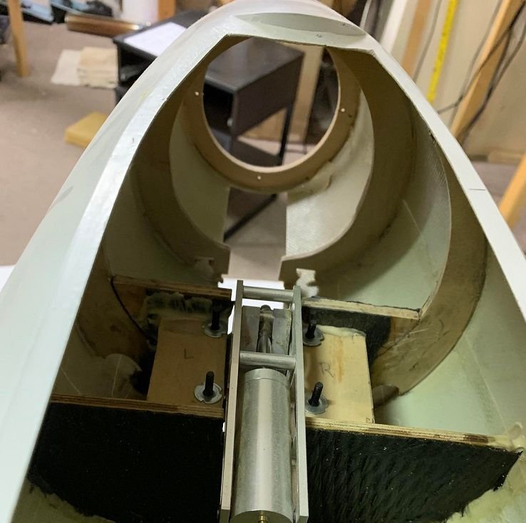
Here are the first three formers installed. The first one is a ring former right where the removable nose is cut off.
The second and third formers hold the nose gear mount plates. As I said, I modified them to move the plates up far enough for the ARF strut length, but I think I'll have to do more modifications to move the nose gear mount towards the rear. That's for later though...
In order to position them correctly, I measured the distance from the nose to the former on the plans, and tack glued small plywood blocks to the sides of the fuselage at that distance to provide a method to hold the formers in the correct location while the Hysol set.
Bob
Last edited by rhklenke; 01-10-2015 at 01:50 PM.
 01-10-2015, 04:57 PM
#302

Thanks for the plug Bob, PM me if you need any still photos for the article. Yes, I really hope things can be worked out for Farview. I'll definitely be in Kentucky so hopefully our paths will cross a few times this year!
nice clean work on the hunter. Certainly more work than most models. But once complete you'll have full confidence in every joint as you did them yourself. There is real value in that.
nice clean work on the hunter. Certainly more work than most models. But once complete you'll have full confidence in every joint as you did them yourself. There is real value in that.
01-17-2015, 03:09 PM
#303
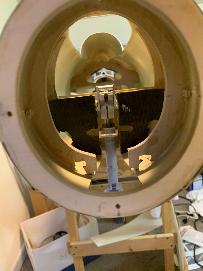
Here's the install of former #4. In the Mick Reeves Hunter, the wing tubes insert into the fuselage and bolt to a small "shelf" on former #4. Here the wing tubes are bolted in as well.


There are plywood plates that glue to the inside of the fuselage at the wing roots that the wing tubes pass through. Gluing these plates in indexes the location of the wing tubes, and thus the wings, in both a vertical and horizontal (longitudinal relative to the fuselage) direction. Thus, the wings need to be on and setup straight before these plates can be glued in place.
The next step is to fit the wings, get them straight, and glue the plates to the side of the fuselage as well as glue the wing tubes into the wings...
01-24-2015, 01:35 PM
#305
The full-scale aircraft I am modeling normally carries three wing pylons and two wing tanks, so I have to add hard-points for those.


It is possible to do that after the wing is sheeted, but doing it before is cleaner. The plans show the location for the two outer pylons and suggest adding a single plywood hard point with a blind nut for each pylon. That's not secure enough for me, and I also don't want to fix the location of the pylons until the wings can be reinstalled to be sure they are straight with respect to the fuselage and each other.
My solution was to add hardwood blocks in the locations where the pylons should bolt on. When I have the pylons built and ready to mount, I'll drill and tap the blocks for the hold-down bolts...
01-24-2015, 11:14 PM
#308

The Swiss flew Mk 58 versions of the Hunter and these have a few differences with the more common Mk 6 that I believe is the Reeves kit. I had a Ripmax Hunter that I had considered using for competition (before realizing there were too many errors) and was using the Mk 58 at the Pima Museum in Tucson, AZ as a reference. Tony Quist and I visited the museum and took a few hundred pics and measurements. I've got them around here somewhere. If you need pics, let me know.
Regards,
Jim
01-25-2015, 11:11 AM
#309
Jim,
I'd be interested in any pictures you have - esp. ones that show surface details and the drogue chute hatches. I'm going to try and make the drogue chute functional. The kit comes with a plastic mounding to fit on the tail for the enclosure, but it doesn't show how the hatches are configured and I haven't been able to find many pictures of that.
Bob
01-28-2015, 11:36 AM
#310
With the mounts for the drop tanks in, its time to sheet the bottom of the wings.
The first thing to do was to smooth out the bottom of the wings with respect to the ribs and the wing spars. The Proskin does not allow any sanding to remove bumps or waves, so everything has to be (almost) perfect before the Proskin is installed. I had some issues where the plywood wing spars protruded out past the ribs and also where some of the plywood ribs in the gear mounting area had a profile that did not match the surrounding ribs. A Dremel sanding drum was used to knock those down and I went with the theory that it was best to have these structures be a little "short" rather than sticking out because the polyurethane glue will expand to fill any gaps.
The wings are sheeted on the bottom by placing them in a cradle made with two plywood supports. I glued those supports to my workbench in the right orientation to support the wing being sheets. When I moved over to the opposite wing, I pulled these supports off the workbench and glued them in the correct orientation for the other wing.


I rough-cut the Proskin out in the wing planview and placed it on top of the wing in the cradle. I then marked the perimeter more carefully and also put index marks on it so I could easily place it back on the wing in the same place. I also marked out where the carbon fiber needed to be for the landing gear reinforcement and where the hatch for access to the landing gear mount needed to be. I "pre-cut" the hatch for the landing gear mount access by scoring the outline with an xacto knife to make cutting it out with a Zona saw later easier.

Once the carbon fiber was applied to the inside of the sheeting, and before it cured, I applied polyurethane glue to the wing structure and placed the wing skin on the wing. After aligning it correctly, I weighed down the skin with long aluminum or carbon fiber bars with weights on top. I also clamped an aluminum angle along the trailing edge of the wing to make sure it was straight.

I took some time to get this all sorted out because once the glue and epoxy have cured, there's no going back!
Bob
The first thing to do was to smooth out the bottom of the wings with respect to the ribs and the wing spars. The Proskin does not allow any sanding to remove bumps or waves, so everything has to be (almost) perfect before the Proskin is installed. I had some issues where the plywood wing spars protruded out past the ribs and also where some of the plywood ribs in the gear mounting area had a profile that did not match the surrounding ribs. A Dremel sanding drum was used to knock those down and I went with the theory that it was best to have these structures be a little "short" rather than sticking out because the polyurethane glue will expand to fill any gaps.
The wings are sheeted on the bottom by placing them in a cradle made with two plywood supports. I glued those supports to my workbench in the right orientation to support the wing being sheets. When I moved over to the opposite wing, I pulled these supports off the workbench and glued them in the correct orientation for the other wing.
I rough-cut the Proskin out in the wing planview and placed it on top of the wing in the cradle. I then marked the perimeter more carefully and also put index marks on it so I could easily place it back on the wing in the same place. I also marked out where the carbon fiber needed to be for the landing gear reinforcement and where the hatch for access to the landing gear mount needed to be. I "pre-cut" the hatch for the landing gear mount access by scoring the outline with an xacto knife to make cutting it out with a Zona saw later easier.
Once the carbon fiber was applied to the inside of the sheeting, and before it cured, I applied polyurethane glue to the wing structure and placed the wing skin on the wing. After aligning it correctly, I weighed down the skin with long aluminum or carbon fiber bars with weights on top. I also clamped an aluminum angle along the trailing edge of the wing to make sure it was straight.
I took some time to get this all sorted out because once the glue and epoxy have cured, there's no going back!
Bob
01-28-2015, 01:23 PM
#311

Join Date: Jul 2006
Location: Norfolk , UNITED KINGDOM
Posts: 1,409
Likes: 0
Received 0 Likes
on
0 Posts
Bob
I am shortly to skin a wing with Proskin. I have used it once before so know some of the issues, but the potential benefits of its use. I see you used PU glue. What make did you use and what do you estimate its curing time was?
best Regards
I am shortly to skin a wing with Proskin. I have used it once before so know some of the issues, but the potential benefits of its use. I see you used PU glue. What make did you use and what do you estimate its curing time was?
best Regards
01-28-2015, 02:18 PM
#312
Join Date: Jul 2005
Location: TroonAyrshire, UNITED KINGDOM
Posts: 97
Likes: 0
Received 0 Likes
on
0 Posts
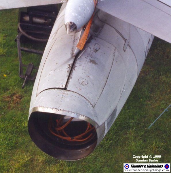
Hi Bob, Here's a photo of the doors: they are either closed like this or fully open. There was not a lot of space above the jet pipe and, from memory, the chute pack was only about 4" thick and was soft packed so it could be squashed in. The Mk 6 did not have a chute, but was later fitted with one as a Mk6A;the Mk9 had one from the start. Interestingly although the T7 had a chute we were not allowed to use it at Chivenor to get us used to landing without one ready for the Mk6!. The Mk6 also could only carry 100 gal tanks whereas the Mk6A and Mk9 could carry 230s inboard
01-28-2015, 02:25 PM
#313
I used Gorilla Glue brand (http://www.gorillatough.com/) - available over here at almost any home improvement store.
It seems to cure fairly quickly (a couple of hours) to the point where its finished foaming and feels dry to the touch. However, I left it overnight on the wing skins with the weights on.
One of my wing panels had somehow warped (probably from hanging around the shop for a year before I got back on the project) and I wanted to be sure it was really cured before I took the weight off least the warp come back. An overnight cure with the weights and the panel is dead straight and stiff as a board...
Bob
01-28-2015, 02:34 PM
#314
Hi Bob, Here's a photo of the doors: they are either closed like this or fully open. There was not a lot of space above the jet pipe and, from memory, the chute pack was only about 4" thick and was soft packed so it could be squashed in. The Mk 6 did not have a chute, but was later fitted with one as a Mk6A;the Mk9 had one from the start. Interestingly although the T7 had a chute we were not allowed to use it at Chivenor to get us used to landing without one ready for the Mk6!. The Mk6 also could only carry 100 gal tanks whereas the Mk6A and Mk9 could carry 230s inboard
Thanks for the picture, that helps a lot! There probably isn't going to be much room in the model for the chute either, although in the model, the pipe is smaller in diameter, so hopefully I can get some room by extending the chute box inward a bit.
The aircraft from Patrouille Suisse I am modeling does have the chute as you can see the doors open in this photo...
01-29-2015, 10:46 AM
#315
Join Date: Jul 2006
Location: Norfolk , UNITED KINGDOM
Posts: 1,409
Likes: 0
Received 0 Likes
on
0 Posts
Hi Bob
Thanks for the info, yes we have Gorilla glue here as well. I have tried it before and it does not foam as much as the Wudgrab glue Mick supplies. The Gorilla glue does not set as quickly and but does not have as much stick though. I am in two minds which to use as I have both in my workshop. I did see a fatastic Mick Reeves kit Spitfire wing that someone made using Proskin and coped with the complex cambers. He used a contact adhesive but not sure which one.
John
02-26-2015, 03:59 PM
#316
I struggled through getting the first wing completed (to the point where it is ready for primer, at least).
Along with the ARF gear, I got one complete landing gear door setup. It took a bit of finagling to get the door in place correctly and my initial cutout for the gear and door had to be adjusted a bit to get it to fit.
I also got the balsa leading edges on and the clear plastic wingtip that came with the kit. I sanded the leading edges down and fared the wingtip in with filler. I cut out the lens cover for the wingtip light (one of the few benefits of having the wingtip molded out of clear plastic). Then I glassed the leading edges and wing tip with two layers of 0.5 oz fiberglass and epoxy.
Finally, I cut out the hatch for the aileron servo. Here's the end result. I'll post some step-by-step pictures as I do the other wing...


Bob
Along with the ARF gear, I got one complete landing gear door setup. It took a bit of finagling to get the door in place correctly and my initial cutout for the gear and door had to be adjusted a bit to get it to fit.
I also got the balsa leading edges on and the clear plastic wingtip that came with the kit. I sanded the leading edges down and fared the wingtip in with filler. I cut out the lens cover for the wingtip light (one of the few benefits of having the wingtip molded out of clear plastic). Then I glassed the leading edges and wing tip with two layers of 0.5 oz fiberglass and epoxy.
Finally, I cut out the hatch for the aileron servo. Here's the end result. I'll post some step-by-step pictures as I do the other wing...
Bob
02-26-2015, 04:15 PM
#317
Step one after the wing is sheeted on both sides is to cut the sheeting away over the landing gear mount area. Then the gear is bolted back onto the mount and the sheeting is cut away as close as possible just to allow the gear to retract in the wing.


Next, the wheel cover portion of the gear door is bolted to the landing gear to determine where the skin should be cut out to clear it. I was lucky enough to get both wheel covers for the main gear - the rest of the gear door assembly for this wing was missing. I'll post pictures of the replacement that I built shortly...

Bob
Next, the wheel cover portion of the gear door is bolted to the landing gear to determine where the skin should be cut out to clear it. I was lucky enough to get both wheel covers for the main gear - the rest of the gear door assembly for this wing was missing. I'll post pictures of the replacement that I built shortly...
Bob
Last edited by rhklenke; 02-27-2015 at 04:56 AM.
02-27-2015, 04:37 AM
#318
That looks really good Bob, I just ordered a second hand kit of the mick reeves hunter as well. and i,m very curius how you will fit the ripmax nose gear because i,m planning to use these retracts aswell.
Geoffrey
Geoffrey
03-01-2015, 02:38 PM
#321
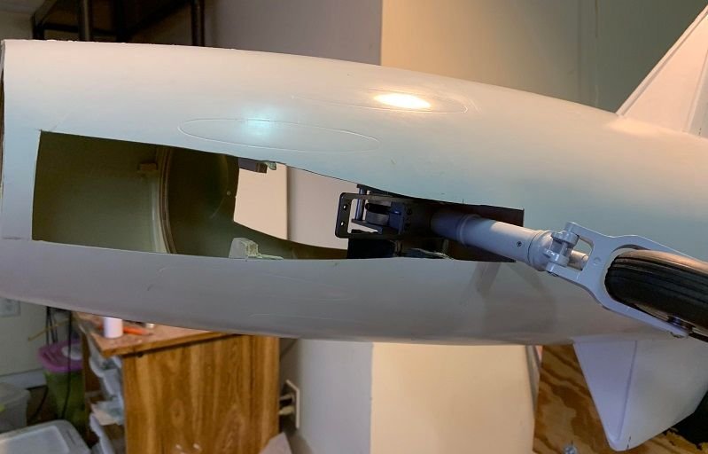
Here is the new gear door mounted and connected to the main gear strut. The next step will be to put the "edging" around the cutout for the main wheel cover to seal that gap when the gear is retracted.


You can also see that there is a "chunk" missing from the corner of the main wheel cover that was apparent crash damage from the original owner that I'll need to fix...
Bob
You can also see that there is a "chunk" missing from the corner of the main wheel cover that was apparent crash damage from the original owner that I'll need to fix...
Bob
06-09-2015, 07:11 AM
#322
Here is the new gear door mounted and connected to the main gear strut. The next step will be to put the "edging" around the cutout for the main wheel cover to seal that gap when the gear is retracted.
You can also see that there is a "chunk" missing from the corner of the main wheel cover that was apparent crash damage from the original owner that I'll need to fix...
Bob
You can also see that there is a "chunk" missing from the corner of the main wheel cover that was apparent crash damage from the original owner that I'll need to fix...
Bob
Regards Geoff
06-09-2015, 10:24 AM
#323
Not at this time. I've been busy at work (again) and haven't gotten up to the shop, other than for maintenance/repair, for a couple of months. I'm planning on getting back to it in a couple of weeks.
First on the "to do" list is to bolt the wings on with the main gear, and figure out exactly where to mount the Ripmax nose gear. As I mentioned above, the Ripmax nose gear is *very* different than the Mick Reeves nose gear so the nose gear mount and associated formers will have to be extensively modified...
More in 3 or 4 weeks, hopefully...
Bob
10-29-2019, 08:40 AM
#324
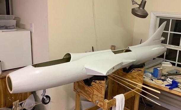
Well its only been 4 years and 4 months, but I'm back on the Hawker Hunter! Before I laid off 4 years ago, I did manage to fit the ARF nose wheel into the Mick Reeves kit. Its a bit further back than scale (at least according to where the nose wheel is on the original kit), but its close and the ARF nose wheel is MUCH better than the one that came with the kit. As an added bonus, somewhere along the line I obtained a complete 2nd set of gear for the ARF, so I have a complete set of spares.
I don't even remember buying them!
Bob
I don't even remember buying them!
Bob
Last edited by rhklenke; 10-29-2019 at 08:46 AM.