


Reaction 54 Jet Kit
 05-11-2016, 03:48 PM
#3476

My Feedback: (1)
Join Date: Jan 2003
Location: Beaumont,
TX
Posts: 57
Likes: 0
Received 0 Likes
on
0 Posts
So....
I got three complete flights on the Reaction and now am having some issues. I've noticed since installing my wren 75 in the fuselage that it starts well the first time, plateauing as it warns the engine and then accelerating nicely.
If I try to start it again just after running it, it comes up to about 15k and 200c and flames out, with the starter still pulling.
If I do this about three times it will start. Let it cool totally and it will start first time.
On flight four I got a flameout after being at full throttle about 100 ft down the runway, and again about 250 ft down the runway, with a full power runup in between. No air bubbles. Shook it while running. No problems, so took it home.
Replaced the egg extension I had in there with one from wren. Same start issues and no runup issues. Haven't flown it as my home field is short and I want some room while troubleshooting it.
BTW its a wren 75 jubilee kero start. running jet A with dte light oil. bought it new used here with about an hour of runtime. Have bench run it a number of times before mounting it.
I'm guessing the 18" of fuel feed from the pump and solenoids to the engine might be part of the problem along with some of our humid weather, but I'm leery of it at the moment.
Any thoughts or ideas. I do have the download cable and can get the latest if there are turbine sages here.
Thanks,
Les
Last edited by lhatton; 05-11-2016 at 04:08 PM.
 05-11-2016, 04:12 PM
#3477

My Feedback: (5)
Join Date: Dec 2011
Location: Holland Patent,
NY
Posts: 717
Likes: 0
Received 0 Likes
on
0 Posts
Les,
Note that the engines has to cool down to less than 100 C before a reliable restart. The 18" fuel feed should not be a problem IF this segment is downstream of the pump-if before the pump that may be an issue. Is the tank clunk mounted to the front or back of the tank-Bruce has run it both ways but I'd prefer the clunk to be aft.
Finally, the flameout might be due to the high temp/humidity in your area. You may want to increase the acceleration delay in the ECU to cope with these conditions. I'd shoot a query to Mike Murphy at: www.wrenpowersystems.com. Mike has been very responsive to queries on my Wrens. Good luck and let us know what you discover is the problem.
Rgds,
Art ARRO
 05-11-2016, 04:48 PM
#3479
Les - what a beautiful paint scheme. Saw that scheme and always thought it was outstanding. You must be awful good with a spray gun. The photos above are the focal point of the elevator cables (crisscrossed from the front servo tray) and the rudder cable (straight line from middle servo). Again, Les, just beautiful. Chic
05-12-2016, 01:46 PM
#3480
My Feedback: (34)
What did you paint the interior wood with??
So here are some more pictures of my Reaction along with the inspiration.
The T50 is used by the South Koreans for thier airshow team, The Black Eagles. I picked the design, looking for something that hadn't been done, and shortly after CARF released the UF in the same pattern. At least I know I didn't pull this finish out of a box.
I still have to install the nose wheel door, but have run into some turbine issues I need to work out. I'll pick your brains in the next post.
05-12-2016, 01:49 PM
#3481
My Feedback: (34)
What are you running for receiver and power system for it? ie Batteries? 1 or 2?
So here are some more pictures of my Reaction along with the inspiration.
The T50 is used by the South Koreans for thier airshow team, The Black Eagles. I picked the design, looking for something that hadn't been done, and shortly after CARF released the UF in the same pattern. At least I know I didn't pull this finish out of a box.
I still have to install the nose wheel door, but have run into some turbine issues I need to work out. I'll pick your brains in the next post.
05-12-2016, 01:53 PM
#3482
My Feedback: (34)
Im using just one A123 2500 Battery and wonder if its enough or people would suggest two. I know the obvious answer is use two for redundancy but wonder how may guys out there are running just one battery to power the radio system. Might think of connecting a second backup battery just for the electric gear but read it doesnt draw that much power anyways
05-12-2016, 02:01 PM
#3483
My Feedback: (1)
Join Date: Jan 2003
Location: Beaumont,
TX
Posts: 57
Likes: 0
Received 0 Likes
on
0 Posts
All automotive paint in the interior, single coat, catalyzed. The exterior is base coat/clear cote, catalyzed.
Engine LIPO is the one pictured 5000mah. Ive got two 3200 life batteries, one on either side of the nose gear, one suppling the receiver, the other a SBUS hub. They all paralleled when on.
All the flight servos are HV SBUS, with the electric gear, brakes, throttle, nose wheel steering, and gear door servo directly off the reciever.
Engine telemetry, and GPS telemetry on the SBUS.
Futaba MZ18 driving it all.
Flys great. Just need to get the engine settled down.
Les

 05-19-2016, 09:53 AM
#3492
My Feedback: (34)
GETTING CLOSER!! Turbine mounted today. After speaking to Bruce, decided to oped hole in turbine mount for glowplug access. All thats left is mounting the ECU, Propane Valve, Switch for AUX brake Battery and Battery for brake, Mount Satellite antennas, Setup all control throws using my Hitec promrammer then Radio, Balance and Fire her up..
Here are some pics of the turbine install.
Johnny


Here are some pics of the turbine install.
Johnny
05-19-2016, 01:25 PM
#3493
My Feedback: (5)
Join Date: Dec 2011
Location: Holland Patent,
NY
Posts: 717
Likes: 0
Received 0 Likes
on
0 Posts
Johnny,
You may want to exchange the Festo filter as these are prone to leak. If on the suction side of the fuel pump then air bubbles may be introduced into the fuel flow-not good. If on the pressure side of the pump you may have a fuel leak and potential fire-even worse. A Hangar 9 filter is a suitable replacement along with a Jet Cat filter. Also, on the glow plug lead, ensure that the alligator clip does not ground itself on the engine mount-if so then you may blow the ECU. Just extend the heat shrink to prevent any unintended contact with the turbine or its mount. Finally, on the trigger valve (another thread) you are missing a flange which secures the assembly to the Powemax canister. You need this flange as part of the assembly. Try to get this flange from whomever you bought the assembly from. There's another type of fitting that can work but the trigger assembly is better- or more cool.
Nice job on the Reaction and it should fly well for you.
Rgds,
Art ARRO
05-19-2016, 05:22 PM
#3494
My Feedback: (34)
Thanks Art ARRO,
SO I have the filter now on the Pressure side, "between the pump and the turbine", Youre saying to install 2 filters?? Or one of the ones you mentioned.. I found the Hanger 9 on Dreamworks but the Jetcat Filter I cant find anywhere. Or they are all sold out.
For the glow plug lead I actually ordered a new cable with the "Cap" for the glowplug from Dreamworks also and will replace the alligator clips.
And for the trigger valve I do have the Flange that goes on the bottle. but when I screw in the valve on the flange that placed on the can I get alot of leaking. Should I be screwing it with the bottle upside down or right side up? or does it not matter??
SO I have the filter now on the Pressure side, "between the pump and the turbine", Youre saying to install 2 filters?? Or one of the ones you mentioned.. I found the Hanger 9 on Dreamworks but the Jetcat Filter I cant find anywhere. Or they are all sold out.
For the glow plug lead I actually ordered a new cable with the "Cap" for the glowplug from
And for the trigger valve I do have the Flange that goes on the bottle. but when I screw in the valve on the flange that placed on the can I get alot of leaking. Should I be screwing it with the bottle upside down or right side up? or does it not matter??
Johnny,
You may want to exchange the Festo filter as these are prone to leak. If on the suction side of the fuel pump then air bubbles may be introduced into the fuel flow-not good. If on the pressure side of the pump you may have a fuel leak and potential fire-even worse. A Hangar 9 filter is a suitable replacement along with a Jet Cat filter. Also, on the glow plug lead, ensure that the alligator clip does not ground itself on the engine mount-if so then you may blow the ECU. Just extend the heat shrink to prevent any unintended contact with the turbine or its mount. Finally, on the trigger valve (another thread) you are missing a flange which secures the assembly to the Powemax canister. You need this flange as part of the assembly. Try to get this flange from whomever you bought the assembly from. There's another type of fitting that can work but the trigger assembly is better- or more cool.
Nice job on the Reaction and it should fly well for you.
Rgds,
Art ARRO
You may want to exchange the Festo filter as these are prone to leak. If on the suction side of the fuel pump then air bubbles may be introduced into the fuel flow-not good. If on the pressure side of the pump you may have a fuel leak and potential fire-even worse. A Hangar 9 filter is a suitable replacement along with a Jet Cat filter. Also, on the glow plug lead, ensure that the alligator clip does not ground itself on the engine mount-if so then you may blow the ECU. Just extend the heat shrink to prevent any unintended contact with the turbine or its mount. Finally, on the trigger valve (another thread) you are missing a flange which secures the assembly to the Powemax canister. You need this flange as part of the assembly. Try to get this flange from whomever you bought the assembly from. There's another type of fitting that can work but the trigger assembly is better- or more cool.
Nice job on the Reaction and it should fly well for you.
Rgds,
Art ARRO
05-19-2016, 11:21 PM
#3495
My Feedback: (5)
Join Date: Dec 2011
Location: Holland Patent,
NY
Posts: 717
Likes: 0
Received 0 Likes
on
0 Posts
Johnny,
You can use one filter, preferably a Hangar 9 or Jet Cat, between the pump and the turbine. I've used the Festo 4 mm myself but was warned against the leakage and switched to the Hangar 9 type just to be safe. A Jet Cat filter was also purchased as a spare from BVM-from the Turbine Accessories part of their website. . The replacement glow plug lead with the rubber boot/cap was a good idea. Otherwise I would have suggested a rubber grommet inserted in the hole of the turbine mount for further protection against a grounding short. On the trigger assembly I noted that you have the flange that attaches to the Powemax canister-this gets mounted first with the trigger part screwed into it, followed but the locking ring. It should not matter whether that canister is upright or inverted as there is a clunk pickup within. You just may have a defective canister-try another. As Powermax canisters are sometimes hard to find I've gone to using "camping gas" canisters and an air/propane tank valve, available from: altecarerc.com. This fitting mounts to the camping gas canisters with a Festo 4 mm outlet which must be mated to a 4mm Festo Ball valve and tubing to your onboard gas tank. You can also eliminate the onboard tank as the camping gas flows only gas when upright. The downside is fussing with the ball valve during the turbine start sequence. The trigger assembly is much simpler/cooler. Let us know how this all works out for you.
Rgds,
Art ARRO
05-20-2016, 08:54 AM
#3497
My Feedback: (5)
Join Date: Dec 2011
Location: Holland Patent,
NY
Posts: 717
Likes: 0
Received 0 Likes
on
0 Posts
Johnny,
On the Jet Cat filter you should hand tighten it initially then let it set overnight or so. On the second tightening you'll note that it will tighten some more as the O-ring compresses. Mount the filter vertically so that any air bubbles are expelled on the initial startup- not later while taking off or during flight. I'd also recommend safety wiring all fuel connections that do not employ a Festo fitting. BVM and Dreamworks both stock suitable safety wire for this. Finally the locking ring is essential for proper trigger valve operation. It's these minor (nit-noi) things that can result in big problems with turbine operation.
Rgds,
Art ARRO
05-20-2016, 10:15 AM
#3498
My Feedback: (34)
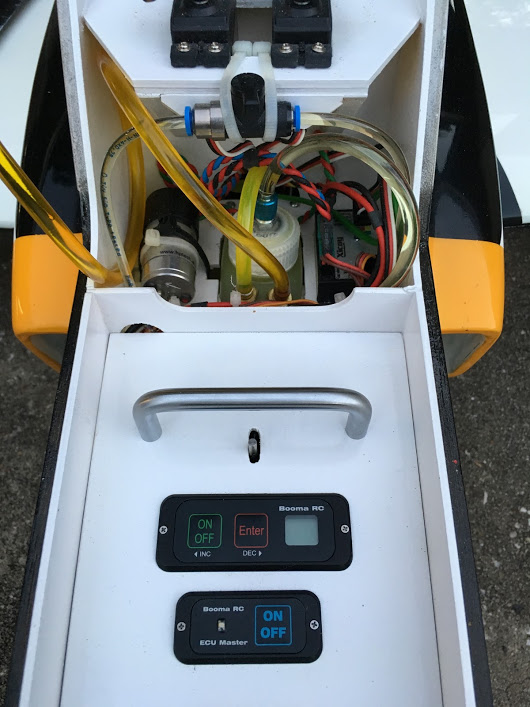
More progress today. Here you see where I mounted the on/off switch for ECU and the propane valve in the upper rear hatch. The ECU will sit just behind it velcroed to the wood. Installed the jetcat fuel filter. I will go back and tidy up all wires and fuel lines. I installed the AUX battery for the gear with a switch as the manual states. But what I thought was strange is that Robart has you install the AUX battery "which is just a 1500 Mah NIMH pack" via a On/Off switch. But when I went to power it up it does not turn on via the switch and Aux battery only. Must have the Whole system powered up, Hence I dont know why they want yo to use the aux battery via an on/off switch if it wont work with the Main rx powered. Now the question is when the system is on, does the electric retracts draw power FIRST from the AUX batter and the main RX pack is there as a backup??? Anyone experience this with their electric retracts from robart on this model or any model for that matter with the Aux battery.


05-20-2016, 11:10 AM
#3499
My Feedback: (1)
Join Date: Jan 2003
Location: Beaumont,
TX
Posts: 57
Likes: 0
Received 0 Likes
on
0 Posts
I think the control box need the radio signal to "control" the gear, but the draw of the motors is off the other battery.
If I remember correct there is a jumper or different plug when you use the separate battery.
Mine all on the radio batteries, but I have 7000mah there.
Also, you might want to extend your fueling line so you have a foot or so rolled up in there. I often spill a little when refueling and you sure don't want it in that bare wood interior.
Les