


JAS-39 Gripen Owners/Build Thread
 10-04-2014, 10:46 AM
#951


Good luck on your maiden. Below is a video of my Gripen maiden and subsequent test flights. The take off was very exciting as I was using the factory recommended aileron throws which were way too sensitive and the plane went knife edge only a few feet off the ground after take off. Please go back in this thread and use the aileron throws listed here. LOTS of expo too (I seem to recall that it's about 60%).
You also mentioned the canard throw and that you were going to lock the canards in position for take off and landing. I would recommend against that for takeoff as you will need the canards to help lift the nose. I agree with locking them for landing and many of us did this to reduce the oscillation you see during final approach in the video.
Later, many of us experimented with having the canards locked at a positive position for landing. With 9mm of up canard (leading edge of canard up), the plane develops a very nice positive AOA in the air that really helps control the approach and landing as you can see in the second video.
http://www.youtube.com/watch?v=y_tXVrL9H4I http://www.youtube.com/watch?v=kP0-unzct4c Regards,
Jim
Last edited by rcjets_63; 10-04-2014 at 10:57 AM.
 10-04-2014, 02:54 PM
#952
Junior Member
My Feedback: (1)
Join Date: Jan 2009
Location: Charlotte, NC
Posts: 12
Likes: 0
Received 0 Likes
on
0 Posts
Thanks for the info. I will go ahead and enable the canards for takeoff and lock them at about 9mm up for landing. I think I will map a knob to it so I can adjust the angle to get it just right 
10-04-2014, 07:28 PM
#953

Hi I did almost the same for my canards except my go up about 10mm and the not disable + mi regular elevators go about 1.5 mm down ,and big thanks to Jim for give me the setup tip about 4 years ago and I blast with my jet before I sold it now I miss mi gripen it was fun jet to fly and extremely fast .
Last edited by sysiek; 10-04-2014 at 07:32 PM.
10-05-2014, 05:01 PM
#954
Junior Member
My Feedback: (1)
Join Date: Jan 2009
Location: Charlotte, NC
Posts: 12
Likes: 0
Received 0 Likes
on
0 Posts
A little too windy for a maiden today. Did get in some taxi tests however,
https://www.youtube.com/watch?v=N8vw...fn930wRZr0H1Yg
https://www.youtube.com/watch?v=N8vw...fn930wRZr0H1Yg
10-06-2014, 11:03 AM
#955
Member

Join Date: May 2004
Location: Kungsbacka, SWEDEN
Posts: 96
Likes: 0
Received 0 Likes
on
0 Posts
Hi
Here is the pneumatic version of the main gear to our 100 % composite Gripen in scale 1/6.
http://youtu.be/2cB_Gxj6qyM //
Jonas
Here is the pneumatic version of the main gear to our 100 % composite Gripen in scale 1/6.
http://youtu.be/2cB_Gxj6qyM //
Jonas
10-07-2014, 08:25 AM
#957

My Feedback: (2)
Join Date: Dec 2007
Location: BloemfonteinFree State, SOUTH AFRICA
Posts: 55
Likes: 0
Received 0 Likes
on
0 Posts
Hi all the Gripen fanatics
We had a beautiful 3 days in Oudtshoorn South Africa. I took the Jim coloured Jas 39 Gripen and my PA F15 and had a lot of fun. The weather was great every day. This was one of the best Oudtshoorn scale events I ever attended for more than 25 years. Some photos of my Gripen.
Fly safe
Pierre Fouch�


We had a beautiful 3 days in Oudtshoorn South Africa. I took the Jim coloured Jas 39 Gripen and my PA F15 and had a lot of fun. The weather was great every day. This was one of the best Oudtshoorn scale events I ever attended for more than 25 years. Some photos of my Gripen.
Fly safe
Pierre Fouch�
Last edited by Rafale; 10-07-2014 at 08:30 AM.
10-08-2014, 12:25 PM
#958
Junior Member
My Feedback: (1)
Join Date: Jan 2009
Location: Charlotte, NC
Posts: 12
Likes: 0
Received 0 Likes
on
0 Posts
Maidened it today!
Couple of notes;
- I disregarded my point of no return takeoff location by ALOT!
- I should have had more up travel on my canards to help with the above point.
- I killed at least one lipo pack and most likely all of them. See picts (I got lucky!)
- We are not allowed to fly turbines at my field so I either need to find a much more efficient power system or sell it
https://www.youtube.com/watch?v=ezp9...fn930wRZr0H1Yg
11-03-2014, 11:01 AM
#960
Hi Guys,
I've restarted my Airworld Gripen build and thought I'd post a bit of info about the model. It sure is a builders kit and there are several scale errors that can be corrected if you want to improve the scale fidelity.
First of all, the nose gear is in the wrong location. The holes in the fore/aft plywood strips onto which the nose gear is mounted are about 1-1/4" too far forward. This error will be easily seen during static as the judges will simply compare the location of the gear strut to the location of the canopy bow.
Picture 1 shows a full scale Gripen with a red line added to show the centerline of the nose strut. Notice how the line falls behind the canopy bow.
Picture 2 shows an Airworld Gripen with the nose gear installed in the stock location. Notice how the nose strut is forward of the canopy bow.
Picture 3 shows the strut in the corrected location. At first glance it appears that I moved the strut too far rearward, but the openable canopy frame isn't installed yet (as it is on the full scale)
Looking at Picture 3, can you see what else is wrong? Notice how the lower front corner of the headrest is in-line with the upper front edge of the air intake. The full scale pic shows the seat is more forward. Also, the glareshield and HUD are too close to the canopy bow. The pic was taken when I was test fitting the cockpit and only had it approximately located. Based on the pictures, I moved it forward about a 1/2" so it matches the full scale.
Last edited by rcjets_63; 11-08-2014 at 03:41 PM.
11-03-2014, 12:24 PM
#961
Another issue with the AW kit is the hinging of the flight controls. The aileron hinges are clearly visible in any top view photo used in your documentation for static judging. The outboard hinge cutout for the elevator is also very obvious.
The kit has the ailerons installed with live hinges. I've yet to see a full scale aircraft with live hinges. I cut the aileron off the wing and redid the leading edge with G-10 hinges and balsa. The middle and inboard hinge farings will be 3D printed and added later.
The stock elevator installation is to slot the elevator in 3 places and install thin G-10 hinges. The full scale Gripen elevator is hinged at the outboard end and in the root (under the blister which contains the elevator actuator/drive) which unfortunately is part of the fuselage in this kit. Unless you want to remove/install the elevators every time you take the wings on/off, additional hinges need to be installed on the elevator. As such, I slotted the elevator for stock hinges at the middle and inboard (they will not be visible with the elevator at neutral). The outboard hinge cutout was replicated and two pieces of G-10 hinge lugs were installed. The fairing on the fuselage as well as the blister on the elevator need to be ground to shape per the full scale.
Picture 1 - Stock wing showing aileron live hinges
Picture 2 - Stock wing with elevator installed - note the slots for the 3 elevator hinges
Picture 3 - Full scale Gripen top view of wing
Picture 4 - Aileron scale hinging
Picture 5 - Elevator hinging
Picture 6 - Elevator actuator blister
Last edited by rcjets_63; 11-03-2014 at 12:32 PM.
11-08-2014, 11:22 AM
#962
Another less-than-scale issue with the Airworld kit is the wheels. For a kit of this expense, it really is disappointing how un-scale the wheels are. As such, after checking the Top Gun "Builder of the Model Rule", I'm having a much more scale set commercially made by Thomas White (invermast) of F-14 fame. Talk about some beautiful work.
Photo 1 - Gripen 39A main wheel
Photo 2 - Gripen 39C main wheel
Photo 3 - Airworld main wheel - machined rim with Dubro 5" tire
Photo 4 - Thomas main wheel rim and tire
Photo 5 - Gripen nose wheel
Photo 6 - Airworld nose wheel - stock Dubro 3" wheel
Photo 7 - Thomas nose wheel
Quite the difference isn't it. I'm really pleased.
Regards,
Jim
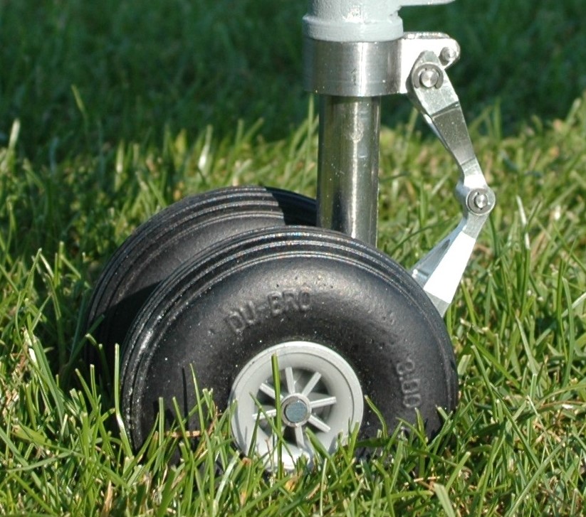
Last edited by rcjets_63; 11-08-2014 at 03:49 PM.
11-08-2014, 02:30 PM
#963

Jim, you have some really cool projects. I admire your attention to detail and disciplined 'eye' to catch the inaccuracies. While admittedly very few people will notice, or even identify the differences, it's exactly those details that will make the finished model look right vs. 'something isn't quite right but I don't know what it is' that we see with a lot of models.
Keep posting, good stuff!
Keep posting, good stuff!
11-25-2014, 11:07 PM
#964
Now that the RePhantom is back in the air, I turned my attention back to the Gripen. The 3D printed wheels arrived from Thomas White, were test fitted, and look great. There are a couple of minor tweeks to do to the 3D models and then they're off to be machined.
I also spent some time locating scale details (vents, holes, grills, scoops, hatches, etc) on the underside of the plane and checking the location of the panel lines. Not surprisingly, several of them are wrong but a large number agree with the electronic model that Saab sent me as well as the many photos I had taken of the Gripens at Caslav Airbase outside of Prague.
Next step will be to check the details on the upper fuselage, and l will possibly spend the holiday weekend cutting off the fin to install spars/receptacles to make it removable for shipping.
Regards,
Jim
Last edited by rcjets_63; 11-25-2014 at 11:10 PM.
11-29-2014, 07:44 PM
#965
Thanksgiving weekend gives 3+ days of workshop time, so I have been looking forward to making some progress on the big Gripen. Many moons ago, I had done some initial work on the hatch and it was time to get it finished. The fit of the stock hatch was, frankly, atrocious which necessitated surgery. The inner liner of the hatch was cut away and the hatch was framed in 1/8" plywood. The outline of the hatch didn't follow any panel lines, so I trimmed the sides to make straight lines which will be easier to blend and hide. The fuselage cutout was similarly lined with plywood. Holes for pins were match drilled in the frames to hold the hatch in place on one side. A Details 4 Scale hidden hatch latch was installed to hold the hatch in position.
I have a few thousand photos of the Gripen so I started drawing the various vents, grills, holes, hatches, fittings, etc on the model to determine where I could drill a through hole to insert the Allen wrench to activate the latch. Unfortunately, there weren't any vents, holes, etc in a workable location. However, there was a double row rivets and, per the photos, a few of them have lost their paint and appear dark so one was selected for the wrench hole.
Regards,
Jim
11-29-2014, 08:01 PM
#966
There really are a surprising number of holes, vents, drains, and even a couple of doo-hickeys on the underside of the Gripen. I laid them all out as I'll have to cut new panel lines for many of these details, as well as fix the incorrect panel lines, and began making the holes and cutouts where needed.
The upper side of the Gripen doesn't have anywhere near the number of features seen on the bottom. There are a couple of vents with louvers/scoops, a couple of raised panels, a view port, and not much more. The primary surface detail on the fuselage of the AW Gripen are the molded-in panel lines and all the screw heads. Unfortunately, most of them are in the wrong location and will have to be filled in :-( which is double the work than if Airworld got it right or left the fuselage plain.
Fortunately, I have a CAD file of the panel locations and I set to work drawing the correct location of the panel lines. This jet is being built for the Jet World Masters, where judges are often known to count rivets/screws. As such, they all needed to be correctly located as well - an example panel is shown in a pic below - the screws/lines with the pencil squiggles through them will be filled in; the correct locations are in black marker.
Regards,
Jim
Last edited by rcjets_63; 11-29-2014 at 08:07 PM.
11-29-2014, 08:23 PM
#968
The AW Gripen is a JAS-39A variant. I'm modeling a JAS-39C variant flown by the Czech Air Force. There are several differences between the A & C, such as the main wheel rims, the use of LED's in the navigation lights at the inlets, and the APU blister. The A & B use the same problematic Microturbo APU while the C & D versions feature a Hamilton Sundstrand APU which is slightly larger and required a local change to the shape of the fuselage.
To make the APU blister, I fit a piece of blue foam, sanded it to shape, and glassed the foam.
Regards,
Jim


To make the APU blister, I fit a piece of blue foam, sanded it to shape, and glassed the foam.
Regards,
Jim
12-02-2014, 11:26 PM
#969
I was getting a bit bored working on the fuselage so I thought I'd mount the pylons on the wings. Easier said than done. Initially, I just lined up the pushrod fairings over the molded in marks in the wing and located the pylons to fit over the fairings. Well, that seriously didn't look right. After two intense evenings of head scratching, math, searching through photos, and scaling them, I finally figured out what was wrong and to do about it.
The pylons provided in the kit are quite incorrect....here's how:
Photo 1 shows the underside of a full scale Gripen. The blue lines show the length from the mounting point of the pylon to the rear edge. The red line shows the length from the mounting point to the front edge. The red lines are obviously different lengths (outboard pylon has a longer red line) but the blue lines are the same length.
Photo 2 shows the kit pylons (outboard pylon on top) Airworld got it backwards, both pylons are the same length from the front to their mounting point but the outboard pylon is longer from the mounting point to the rear edge.
Photo 3 shows a nice close up of the mounting pad of the inboard pylon of a full scale Gripen. Notice how the mounting pad is in the shape of an ellipse.
Photo 4 shows the Airworld pylon mounting pad. Not even close to the shape of the full scale. The pad should be a 4' long x 1.9" wide ellipse as shown.
To further "tweek" the problem, the location of the panel lines for the leading edge flap are wrong which also threw me off for a while until I figured that out.
The correct mounting dimensions for the pylons are shown in photo 5. Also shown is the corrected leading edge flap panel line (in black marker), the outline of the AW pylon mounting pad is shown in a dashed line, and the correct ellipse shape is shown in a solid black line. Comparing the mark up to photo 3 of the full scale shows they match.
Photo 5 shows 5/8" diameter circles around the mounting bolt locations for the pylons. The plan was to grind out these holes to and Hysol a 5/8" diameter hardwood dowel vertically in the wings to receive a threaded insert for mounting the pylons.
As it turns out, the outboard hole of the inboard pylon lands on a wing rib and the inboard hole of the outboard pylon falls smack dab on the spar. See Photo 6. The rib isn't that much of a problem but the spar is a concern. It looks like I can just get the insert (but not the dowel) in the right location if I pot it in place using Hysol. I'll further inspect the wing with a borescope or have it X-ray'd to know for sure.
Of course, I still have to take care of the issue of the outboard pylon being too long in back but too short in front. It might be necessary to mold an accurate pair of outboard pylons. :-(
Regards,
Jim
Last edited by rcjets_63; 12-02-2014 at 11:36 PM.
 12-03-2014, 10:45 PM
#971
Here are the borescope results:
Photo 1 - view looking outboard at holes and sub-rib at inboard pylon mount. The rib intersects the outboard hole as shown in photo 6 of post #969. As a solution, I notched the top of the rib to receive the full dowel at the top and I will trim away the outboard side of the dowel at the bottom. The dowel can then be glued to the upper wing skin, rib, and lower wingskin
Photo 2 - view looking outboard along forward side of spar shown in photo 6 of post #969. The spar is just a layer of fiberglass on a core of blue foam. There is a layer of carbon fibre installed between the spar and the wing skin and I nicked the edge of this slightly when I drilled the hole for the outboard pylon's outboard mounting hole. It's just a slight nick and really nothing to worry about.
Photo 3 - View looking forward at the aft side of the spar shown in photo 6 of post #969 showing a notch in the aft side of the spar where I had ground hole for the outboard pylon's inboard mount.
The inboard mount takes away a bit more CF than I would have liked. As such, I'll just pot the insert in place here (rather than installing a dowel) and will laminate a layer of carbon fibre on the along the lower wing skin aft of the spar to restore the strength. This area is reasonably accessible through the aileron servo cutout.
Regards,
Jim


P.S.: A borescope is an exceedingly handy tool to have. If you don't have access to one at work, you can get a pretty good one from DreamWorks for $64. That's a pretty low price for a tool that one day may let you find a structural problem and save you from a crash.
Photo 1 - view looking outboard at holes and sub-rib at inboard pylon mount. The rib intersects the outboard hole as shown in photo 6 of post #969. As a solution, I notched the top of the rib to receive the full dowel at the top and I will trim away the outboard side of the dowel at the bottom. The dowel can then be glued to the upper wing skin, rib, and lower wingskin
Photo 2 - view looking outboard along forward side of spar shown in photo 6 of post #969. The spar is just a layer of fiberglass on a core of blue foam. There is a layer of carbon fibre installed between the spar and the wing skin and I nicked the edge of this slightly when I drilled the hole for the outboard pylon's outboard mounting hole. It's just a slight nick and really nothing to worry about.
Photo 3 - View looking forward at the aft side of the spar shown in photo 6 of post #969 showing a notch in the aft side of the spar where I had ground hole for the outboard pylon's inboard mount.
The inboard mount takes away a bit more CF than I would have liked. As such, I'll just pot the insert in place here (rather than installing a dowel) and will laminate a layer of carbon fibre on the along the lower wing skin aft of the spar to restore the strength. This area is reasonably accessible through the aileron servo cutout.
Regards,
Jim
P.S.: A borescope is an exceedingly handy tool to have. If you don't have access to one at work, you can get a pretty good one from DreamWorks for $64. That's a pretty low price for a tool that one day may let you find a structural problem and save you from a crash.
12-03-2014, 11:34 PM
#972
I also took George's hint and went back to work on the fuselage. The Gripen has an aft facing outlet scoop on the right rear fuselage and the folks at Airworld molded this into the fuselage of the model.
Photo 1 shows the vent/scoop and the surrounding features of the full scale aircraft. The vent/scoop sits on it's own panel and is located under the aft formation light on the fin. From the green lines I added, you can see how the features of the scoop and panel align with the formation lights and the panel lines on the fin.
Photo 2 shows the model. It isn't the greatest photo so I added red lines where the panel lines are on the model and colored in the molded in outlines of the formation lights.
By comparing the photos, you can see that the scoop, and it's underlying panel is very much in the wrong location.
OK, so what to do about it.....obviously the scoop has to move to match photo 1. Here's one way:
Photo 3 shows a "dam" made of blue modeler's clay around the scoop.
Photo 4 shows the area filled in with silicon molding compound http://www.bjbenterprises.com/tc-5061-a-b/
Once the silicon dries (overnight), it can be peeled off the fuselage as a female mold for the scoop. I'll sand off the existing scoop, and simply use the mold to make another scoop (using a resin/microballoon mixture) which I can glue on the model at the scale location. This is a fast and easy way to "splash" a feature and can also be used to make quick molds for antennas, lights, etc.
The shape of the scoop isn't quite right either, but that's easy enough to fix with a bit of Bondo.
Note: The silicon is a two part mixture and when you mix it, you'll introduce air bubbles as you can see in photo 4. I forgot to put my mixing dish under vacuum (I built a vacuum pump for molding fuel tanks a few years ago) for a few minutes to draw out most of the air bubbles for an even better surface finish of the mold.
Regards,
Jim
Last edited by rcjets_63; 12-03-2014 at 11:39 PM.
12-05-2014, 08:45 PM
#975
Further to posts 969 (pylon placement) and 972 (scoop placement), here are the results of the relocation of these items.
Photo 1 - side view of full scale showing front of pylons
Photo 2 - side view of model


The full scale plane is yawed slightly left (nose closer to camera) so the front of the pylons will appear slightly aft of where they would if the picture was a pure side view (taken at 90 degrees from the centerline. There are two small blade-style antennas mounted on the dorsal fin (I colored them in red for visibility).
- the front of the inboard pylon is aligned with the forward antenna per the full scale
- the front of the outboard pylon is too far aft as predicted in post 969 because the pylon itself is incorrect (too short from front edge to pylon mount). I will mold correct outboard pylons
Photo 3 - side view of full scale showing formation lights and fuselage scoop
Photo 4 - side view of model


- the relocated panel and new molded scoop now correctly aligns with the aft formation light and the panel lines
- the scoop needs to be shaped a bit to match the full scale
Unfortunately, the bad luck I had relocating the pylons (holes for outboard pylon mount interfered with wing spar) is continuing. Airworld placed a fuselage former exactly where the hole in the fuselage has to made. Nothing is easy with this plane :-( As such, I will grind away the portion of the former near the hole and reinforce the former as required and paint black any visible part of the former.
Regards,
Jim
Photo 1 - side view of full scale showing front of pylons
Photo 2 - side view of model
The full scale plane is yawed slightly left (nose closer to camera) so the front of the pylons will appear slightly aft of where they would if the picture was a pure side view (taken at 90 degrees from the centerline. There are two small blade-style antennas mounted on the dorsal fin (I colored them in red for visibility).
- the front of the inboard pylon is aligned with the forward antenna per the full scale
- the front of the outboard pylon is too far aft as predicted in post 969 because the pylon itself is incorrect (too short from front edge to pylon mount). I will mold correct outboard pylons
Photo 3 - side view of full scale showing formation lights and fuselage scoop
Photo 4 - side view of model
- the relocated panel and new molded scoop now correctly aligns with the aft formation light and the panel lines
- the scoop needs to be shaped a bit to match the full scale
Unfortunately, the bad luck I had relocating the pylons (holes for outboard pylon mount interfered with wing spar) is continuing. Airworld placed a fuselage former exactly where the hole in the fuselage has to made. Nothing is easy with this plane :-( As such, I will grind away the portion of the former near the hole and reinforce the former as required and paint black any visible part of the former.
Regards,
Jim