


JAS-39 Gripen Owners/Build Thread
 12-06-2014, 03:39 AM
#976

Your attention to detail and discipline to get it accurate is inspiring Jim. Thanks for showing the effort it takes! I may have to stop using one of my favorite sayings, that it takes just as long to do it right as it does to do it wrong. This thread is evidence that isn't the case!
keep posting, great stuff here!!
keep posting, great stuff here!!


 12-07-2014, 03:05 PM
#978

Now that the rear scoop and pylons are fixed, I thought I'd move onto the cockpit and canopy. I've seen pics of a couple of other AW Gripens and one of the things that I noticed is that the curve of the canopy seemed wrong in those pics. I was really hoping that I wouldn't have to mold a new canopy to get it correct, and the good news (finally, some good news) is that the canopy seems to be a pretty good match for the full scale, you just have to be careful to cut it from the right part of the AW molded canopy.
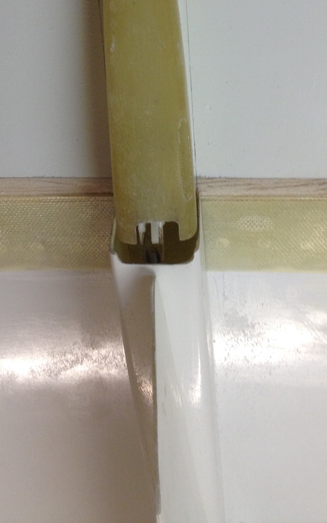
You can see in the pic below, the clear canopy laying over the fuselage and green canopy frame. All I have done to the molded canopy at this point is cut off about 1/2" from the front and the back in order to lay it in place. In order to get the curve of the top of the canopy to match the full scale, you have to offset the canopy almost all the way forward. The natural tendency would be to center the canopy (same amount of clear material in front of frame as behind the frame) and I think this is what a couple of other AW Gripen builders did.
Regards,
Jim
12-07-2014, 03:40 PM
#979
I'm editing this post to correct it based on some new information I received from Airworld.
Now for the bad news....the canopy frame. Every other kit that I've built has had a canopy frame/upper fuselage section molded from a few layers of glass cloth. Taking a cross-section of the piece would form an "L" where the lower part (the _ ) is a stiffening flange that mates with the fuselage and the upright part (the I ) follows the fuselage shape and is the surface to which you glue the canopy. Not so with this kit. The provided canopy frame has a square cross section.
I was a bit confused by this square cross section, and when I looked at the photos (provided with the kit) it looks as if the frame has a conventional L-shaped cross section.
Photo 1: Photo provided by AW with the kit. The cross section of the frame is clearly L-shaped.

Based on this, I proceed to cut away the upper horizontal and the inboard vertical sides to produce a frame with an L-shaped cross section. This effort was pretty much a disaster due to the molding being essentially solid in some areas and having large voids in others. I made a couple of jigs to take care of sanding the sides of the canopy frame, but I had to free-hand grind the corners.
Photos 2 & 3 - the canopy frame after grinding (L-shaped section remaining)
Photos 4 & 5 - close ups showing voids and thicknesses


I would consider it extremely unlikely that ANYBODY could accurately grind this item to produce a nice consistent piece the thickness of a few layers of glass cloth unless they are a Picasso with a Dremel tool (I'm not).
I contacted Airworld and they provided several new photos and stated that the canopy is supposed to be installed OVER the square frame. Here are the pics they sent:
Photos 6 - 8: Photos provided 12/9/14 by Airworld in response to my email about this issue.


In these photos, the canopy has clearly been glued to the exterior of the frame and the edges painted. I cannot tell if the builder notched the outside of the frame to make a recess for the canopy, or if the canopy extends all the way to the edge of the frame. Either way, the completed canopy assembly as shown doesn't follow the fuselage shape very well, particularly at the rear lower corner as seen in photo 6.
This photo, included on the photo CD, appears to show a different frame (L-shaped) that is a much better fit to the fuselage contour. Perhaps it was a prototype that has since been replaced by the square frame.

Regardless, the square frame is what is provided now and you are supposed to glue the canopy to the exterior of the frame. I supposed you can either notch the frame for that canopy and/or build it up with filler to blend it into the fuselage and then paint the edges. The end result might look OK; I never have had a lot of luck using filler to blend clear lexan canopies (but maybe that's just me).
Since I cut up my square canopy frame and I don't think the AW frame is a very workable or scale solution, I will mold my own L-shaped scale frame. The Gripen frame has notches in the right side of the frame but none on the left per the two pics below. The AW frame doesn't have the notches. The notches are obvious features of the frame that any static judge would easily see in the documentation photos so they need to be on the model too.


Not sure about the selection of head gear by the Czech pilot in the last pic. You had to be there, I guess.
Regards,
Jim
Now for the bad news....the canopy frame. Every other kit that I've built has had a canopy frame/upper fuselage section molded from a few layers of glass cloth. Taking a cross-section of the piece would form an "L" where the lower part (the _ ) is a stiffening flange that mates with the fuselage and the upright part (the I ) follows the fuselage shape and is the surface to which you glue the canopy. Not so with this kit. The provided canopy frame has a square cross section.
I was a bit confused by this square cross section, and when I looked at the photos (provided with the kit) it looks as if the frame has a conventional L-shaped cross section.
Photo 1: Photo provided by AW with the kit. The cross section of the frame is clearly L-shaped.
Based on this, I proceed to cut away the upper horizontal and the inboard vertical sides to produce a frame with an L-shaped cross section. This effort was pretty much a disaster due to the molding being essentially solid in some areas and having large voids in others. I made a couple of jigs to take care of sanding the sides of the canopy frame, but I had to free-hand grind the corners.
Photos 2 & 3 - the canopy frame after grinding (L-shaped section remaining)
Photos 4 & 5 - close ups showing voids and thicknesses
I would consider it extremely unlikely that ANYBODY could accurately grind this item to produce a nice consistent piece the thickness of a few layers of glass cloth unless they are a Picasso with a Dremel tool (I'm not).
I contacted Airworld and they provided several new photos and stated that the canopy is supposed to be installed OVER the square frame. Here are the pics they sent:
Photos 6 - 8: Photos provided 12/9/14 by Airworld in response to my email about this issue.
In these photos, the canopy has clearly been glued to the exterior of the frame and the edges painted. I cannot tell if the builder notched the outside of the frame to make a recess for the canopy, or if the canopy extends all the way to the edge of the frame. Either way, the completed canopy assembly as shown doesn't follow the fuselage shape very well, particularly at the rear lower corner as seen in photo 6.
This photo, included on the photo CD, appears to show a different frame (L-shaped) that is a much better fit to the fuselage contour. Perhaps it was a prototype that has since been replaced by the square frame.
Regardless, the square frame is what is provided now and you are supposed to glue the canopy to the exterior of the frame. I supposed you can either notch the frame for that canopy and/or build it up with filler to blend it into the fuselage and then paint the edges. The end result might look OK; I never have had a lot of luck using filler to blend clear lexan canopies (but maybe that's just me).
Since I cut up my square canopy frame and I don't think the AW frame is a very workable or scale solution, I will mold my own L-shaped scale frame. The Gripen frame has notches in the right side of the frame but none on the left per the two pics below. The AW frame doesn't have the notches. The notches are obvious features of the frame that any static judge would easily see in the documentation photos so they need to be on the model too.
Not sure about the selection of head gear by the Czech pilot in the last pic. You had to be there, I guess.
Regards,
Jim
Last edited by rcjets_63; 12-10-2014 at 01:16 PM.
12-07-2014, 07:45 PM
#980
Here is the right side of the plug I made for the canopy frame and the full scale for comparison. I only have to make one frame so there is no sense making a standalone mold. After doing the left side of the plug (hopefully tomorrow), I'll just wax the plug and surrounding area of the fuselage and lay up the fiberglass on top to make the female mold of the fuselage. Then the canopy plug can be removed and the canopy frame laid up.
Regards,
Jim


Regards,
Jim
12-08-2014, 08:24 PM
#981
Prototype 3D printed rims and tires installed for fit checks. The final versions will be machined from aluminum with molded rubber tires and the scale caps over the axles. You gotta admit, they look soooo much better than the AW wheels.
Regards,
Jim
Regards,
Jim
 12-10-2014, 09:58 AM
#983
I edited post #979 (canopy frame) based on some new photos I received from Airworld. The photos included with the kit appear to show an L-shaped frame not the square-shaped frame in the kit. The canopy is supposed to be glued to the OUTSIDE of the square-shaped frame.
I cut up my square frame and have started molding my own frame so this new info doesn't make much of a difference to me; I just wanted to share the new info/photos with anyone who may build an AW Gripen (like Roy). I'm finishing off the frame plug now (photo below shows the left side wooden blocks before sanding) and should be molding the new frame later this week.
Regards,
Jim
12-10-2014, 12:41 PM
#984
Junior Member
Join Date: Jun 2011
Location: Aarle Rixtel, NETHERLANDS
Posts: 8
Likes: 0
Received 0 Likes
on
0 Posts
Lots of work to correct a supposed to be accurate scale kit.
I hope the new swedish kit is much better.
I like the way you tackle this job and post this with pictures here very much.
Keep up the good job.
I hope the new swedish kit is much better.
I like the way you tackle this job and post this with pictures here very much.
Keep up the good job.
12-10-2014, 01:39 PM
#985

My Feedback: (35)
Join Date: May 2002
Location: Springfield, IL
Posts: 1,616
Likes: 0
Received 0 Likes
on
0 Posts
Jim I sure will have a greater appreciation, having viewed your corrections, when I see the model.
I'm certain your efforts/talents will go a long way toward our goal for the JWM Team USA to bring home the hardware
from Germany in August.
Oh by-the-way I'll have the final say, before startup, on weather clearance ! ! !
I'm certain your efforts/talents will go a long way toward our goal for the JWM Team USA to bring home the hardware
from Germany in August.
Oh by-the-way I'll have the final say, before startup, on weather clearance ! ! !
Last edited by Roger Shipley; 12-10-2014 at 01:52 PM.
12-11-2014, 09:47 PM
#987
My Feedback: (35)
Join Date: May 2002
Location: Springfield, IL
Posts: 1,616
Likes: 0
Received 0 Likes
on
0 Posts
QUOTE=rcjets_63;11935144]Fine, you have the final say in the mid-west.
How much experience do you have with sudden storms in Bavaria
Well lets see, 2 years & 9 months the first time, then a 3 week venture including the 1st JWM & a couple of trips to the annual IJMC meeting to promote hosting the 9th JWM at the National Museum of the US Air Force. Probably as qualified as any available yank could be, huh.
You know what Jim, maybe I should take you under my wing to maximize your potential....don't ya think?[
Jim[/QUOTE]
12-12-2014, 06:16 PM
#988
The aft edge of the elevator actuator blister on the full scale Gripen is not even with the trailing edge of the fixed portion of the wing. See photo 1. It is trimmed forward about 15mm (3 mm on the model's scale). The fuselage layup is particularly thick in this area rather than coming down to a nice thin scale edge so I'll cut it will have to be cut back a bit more and a .005" thick piece of Poly Ply will be laminated to the skin and blended into the fuselage.
The portion of the blister on the elevator itself houses the attachment point for the elevator actuator rod. The front edge is cut at a few angles in this region as seen in the photo. It is hard to tell in photo 2, but the contour of the blister on the elevator doesn't really follow the blister on the fuselage and this will have to be corrected (more Bondo).
Photo 1 - full scale Gripen showing the curvature of the aft edge of the elevator actuator blister. The hydraulics are off so the elevator is at 35 degrees down.
Photo 2 - AW Gripen with elevator actuator blister trimmed to match. Front of elevator has been over-trimmed; I needed access to fix the routing of the tube molded into the elevator for the hinge pin. It will get restored when I fix the blister contour.
You can also see in Photo 2 the slot for the inboard elevator hinge. Not scale, but it sure makes life easier when removing the wings after a day of flying (something they don't do with the full scale Gripen)
Regards,
Jim
Last edited by rcjets_63; 12-12-2014 at 06:22 PM.
12-13-2014, 03:52 PM
#989
Now that the location of the wing pylons was determined and the pylons mounted, I turned my attention to the molded fairings which are sandwiched between the pylons and the wing. Note, both the inboard and outboard fairings do NOT end flush with the wing/aileron and wing/elevator junction as seen in photo 1. Both fairings are chamfered at the wing/fairing joint to allow movement of the elevator & aileron. The aft edge of the outboard fairing is vertical, while the inboard fairing is angled at 35 degrees.
Photo 1 - view looking outboard from below fuselage showing wing/pylon fairings. Elevator fairing in foreground, aileron fairing beyond.

The fairings provided in the kit are sized for the incorrect pylon locations so some modifications have to be made. The outboard fairing is too long and simply needs about 7/8" trimmed off the back. The inboard fairing is too short and needs to be extended. Rather than remold the fairing, I simply modified it by cutting it about 1-3/8" from the back edge, and splicing a 2" long section in the middle. Splicing in the middle is necessary because the fairing is curved and if you simply extend it rearwards, it will be too small to fit the fairing under the elevator. I spliced in a 2" length of balsa, sanded it to shape, and used it to make a mold. It will be easy enough to lay up a few layers of glass in the mold and then splice this into the fairing to replace the balsa.
Photo 2 - AW fairing with balsa section spliced in. Dam for mold build around this area.
Photo 3 - Mold filled in with molding silicone.


Unfortunately, the AW kit does NOT include the fairing mounted below the aileron :-( The fairing is 4+ inches long and 3/4+ inches wide and it's absence would certainly be noted during static judging of side, aft, and bottom of aircraft and you'd certainly take a deduction.
Photo 5 - AW supplied photo of bottom of wing. Where is the fairing?
Photo 6 - Full scale Gripen 9245 with the fairing circled.


So, the aileron fairing has to be made. I carved a balsa block to shape to use as a plug, poured a mold, and laid up a fiberglass fairing.
Photo 7 - Balsa plug of aileron fairing and silicone mold
Photo 8 - Fiberglass layup in mold


Photo 9 - Test fitting the newly molded aileron fairing on the model. Much better!

Regards,
Jim
Photo 1 - view looking outboard from below fuselage showing wing/pylon fairings. Elevator fairing in foreground, aileron fairing beyond.
The fairings provided in the kit are sized for the incorrect pylon locations so some modifications have to be made. The outboard fairing is too long and simply needs about 7/8" trimmed off the back. The inboard fairing is too short and needs to be extended. Rather than remold the fairing, I simply modified it by cutting it about 1-3/8" from the back edge, and splicing a 2" long section in the middle. Splicing in the middle is necessary because the fairing is curved and if you simply extend it rearwards, it will be too small to fit the fairing under the elevator. I spliced in a 2" length of balsa, sanded it to shape, and used it to make a mold. It will be easy enough to lay up a few layers of glass in the mold and then splice this into the fairing to replace the balsa.
Photo 2 - AW fairing with balsa section spliced in. Dam for mold build around this area.
Photo 3 - Mold filled in with molding silicone.
Unfortunately, the AW kit does NOT include the fairing mounted below the aileron :-( The fairing is 4+ inches long and 3/4+ inches wide and it's absence would certainly be noted during static judging of side, aft, and bottom of aircraft and you'd certainly take a deduction.
Photo 5 - AW supplied photo of bottom of wing. Where is the fairing?
Photo 6 - Full scale Gripen 9245 with the fairing circled.
So, the aileron fairing has to be made. I carved a balsa block to shape to use as a plug, poured a mold, and laid up a fiberglass fairing.
Photo 7 - Balsa plug of aileron fairing and silicone mold
Photo 8 - Fiberglass layup in mold
Photo 9 - Test fitting the newly molded aileron fairing on the model. Much better!
Regards,
Jim
Last edited by rcjets_63; 12-13-2014 at 06:38 PM.
12-14-2014, 12:06 PM
#990
Elevator Control Horn
The Airworld-supplied build photos (see photo 1) show two G10 control horns (supplied in kit) being glued into slots in the elevator blister and a rod end installed between the horns. While this will certainly work, I am concerned that the 4-40 bolt & lock nut used to secure the rod end to the control horns might be too wide for the fairing and I'd have to cut away the fairing to prevent any binding. Also, due to the outer diameter of the rod end itself, the height of the control horn would have to be reduced to prevent the rod end from interfering with the fairing.
Photo 1 - Airworld-supplied photo showing elevator control connection

My preferred connection would be a single G-10 control horn with a Sullivan 4-40 Gold-N-Clevis, 4-40 threaded rod (with CF tube reinforcement), Dubro 4-40 Safety Lock Kwik Link, and a SWB servo arm. The big question though is would it be strong enough? Obviously, if the elevator linkage breaks, the likelihood of getting the plane back in one piece is seriously reduced so getting this right is rather important.
So I did a few calculations and some testing as follows:
I'm using a JR8711 servo (rated at 403 oz-in @ 6V) and a 3/4" long SWB servo arm. This means that the maximum force which could be generated by the servo is 403/.75 = 537 oz.
I built a mock-up of the control linkage (see photo 2) using the SWB arm, Dubro Kwik Link, 4-40 rod, Sullivan clevis, and a single piece of .063 thick G-10 cut to the same size as the .056 thick kit-supplied horns. I hung this up using a piece of coat hanger through the SWM arm hole for the servo screw, used a pair of vice grips to grab the G10, and started hanging weight on the vice grips. The linkage failed at 56 lbs (896 oz).
The point of failure was the control horn where it was squeezed by the vice grips (see photo 3). This created a local stress concentration so this point of failure wasn't surprising. A careful inspection of all parts showed no other damage.
The safety factor on this is 896/537 = 1.67. In other words, this linkage is 1.67 times as strong as the maximum force the servo could generate so this linkage will be OK.
On the model, I'll also use a wider control horn (to provide more gluing surface and better load transfer into the elevator) which will further increase the safety factor.
Photo 2 - elevator linkage for testing.
Photo 3 - elevator linkage tested to failure. G-10 control horn failed at 896 oz


Regards,
Jim
The Airworld-supplied build photos (see photo 1) show two G10 control horns (supplied in kit) being glued into slots in the elevator blister and a rod end installed between the horns. While this will certainly work, I am concerned that the 4-40 bolt & lock nut used to secure the rod end to the control horns might be too wide for the fairing and I'd have to cut away the fairing to prevent any binding. Also, due to the outer diameter of the rod end itself, the height of the control horn would have to be reduced to prevent the rod end from interfering with the fairing.
Photo 1 - Airworld-supplied photo showing elevator control connection
My preferred connection would be a single G-10 control horn with a Sullivan 4-40 Gold-N-Clevis, 4-40 threaded rod (with CF tube reinforcement), Dubro 4-40 Safety Lock Kwik Link, and a SWB servo arm. The big question though is would it be strong enough? Obviously, if the elevator linkage breaks, the likelihood of getting the plane back in one piece is seriously reduced so getting this right is rather important.
So I did a few calculations and some testing as follows:
I'm using a JR8711 servo (rated at 403 oz-in @ 6V) and a 3/4" long SWB servo arm. This means that the maximum force which could be generated by the servo is 403/.75 = 537 oz.
I built a mock-up of the control linkage (see photo 2) using the SWB arm, Dubro Kwik Link, 4-40 rod, Sullivan clevis, and a single piece of .063 thick G-10 cut to the same size as the .056 thick kit-supplied horns. I hung this up using a piece of coat hanger through the SWM arm hole for the servo screw, used a pair of vice grips to grab the G10, and started hanging weight on the vice grips. The linkage failed at 56 lbs (896 oz).
The point of failure was the control horn where it was squeezed by the vice grips (see photo 3). This created a local stress concentration so this point of failure wasn't surprising. A careful inspection of all parts showed no other damage.
The safety factor on this is 896/537 = 1.67. In other words, this linkage is 1.67 times as strong as the maximum force the servo could generate so this linkage will be OK.
On the model, I'll also use a wider control horn (to provide more gluing surface and better load transfer into the elevator) which will further increase the safety factor.
Photo 2 - elevator linkage for testing.
Photo 3 - elevator linkage tested to failure. G-10 control horn failed at 896 oz
Regards,
Jim
Last edited by rcjets_63; 12-14-2014 at 12:08 PM.
12-14-2014, 11:02 PM
#991
I managed to get a few more things done today (and even gave the dogs a haircut - they're not happy)
Photo 1 - Full scale Gripen fairing under aileron
Photo 2 - Model with fairing installed and trimmed to match. A bit of black paint on the aileron control horn and the clevis inside will help hide these bits as well as match the full scale. Note: This pylon was cut to length previously which left it's trailing edge about 1/4" wide. I cut it down the centerline on a taper and pulled the sides in to match the correct thickness of the pylon trailing edge.

I'll glue some strips of rectangular carbon fibre to the edges of the fairing where it meets the wing. These will stiffen the edge and match the full scale.
Also, taking a lesson from the BVM Bandit instructions, I built a jig to locate the elevator control horn. Once the Hysol is dry, I'll use it on the other elevator to make sure that both control horns are installed exactly the same.
Photo 3 & 4 - Elevator control horn installed with jig. Extra holes were drilled into the underside of the elevator to inject Hysol to lock the control horn and the hinge pin tubing in place. These can be easily filled afterwards.


Regards,
Jim
Photo 1 - Full scale Gripen fairing under aileron
Photo 2 - Model with fairing installed and trimmed to match. A bit of black paint on the aileron control horn and the clevis inside will help hide these bits as well as match the full scale. Note: This pylon was cut to length previously which left it's trailing edge about 1/4" wide. I cut it down the centerline on a taper and pulled the sides in to match the correct thickness of the pylon trailing edge.
I'll glue some strips of rectangular carbon fibre to the edges of the fairing where it meets the wing. These will stiffen the edge and match the full scale.
Also, taking a lesson from the BVM Bandit instructions, I built a jig to locate the elevator control horn. Once the Hysol is dry, I'll use it on the other elevator to make sure that both control horns are installed exactly the same.
Photo 3 & 4 - Elevator control horn installed with jig. Extra holes were drilled into the underside of the elevator to inject Hysol to lock the control horn and the hinge pin tubing in place. These can be easily filled afterwards.
Regards,
Jim
Last edited by rcjets_63; 12-14-2014 at 11:23 PM.
12-16-2014, 10:13 AM
#992
The silicon mold for the inboard fairing (as developed in post 989) also acts as jig to align the two pieces of the fairing while the fiberglass splice/extension is layed up.
Photo 1 - Silicon mold to extend inboard (elevator) fairing with the modified fairing.

Photo 2 & 3 - View under right wing of full scale Gripen showing fairings at pylons/elevator/aileron and similar photo of the model for comparision


Here's an overall view of the underside of the wing. The pylons themselves need to be further modified (add length to front of outboard pylon, modify mounting area of both pylons to make them eliptical in shape) but as they are now they are OK to fly.

The next step is to attach the fairings to the underside of the wing in such a way that the mounting hardware is hidden but the fairings are easily removeable to access the servos. I'll use a similar method to that for the BVM Rafale.
Regards,
Jim
Photo 1 - Silicon mold to extend inboard (elevator) fairing with the modified fairing.
Photo 2 & 3 - View under right wing of full scale Gripen showing fairings at pylons/elevator/aileron and similar photo of the model for comparision
Here's an overall view of the underside of the wing. The pylons themselves need to be further modified (add length to front of outboard pylon, modify mounting area of both pylons to make them eliptical in shape) but as they are now they are OK to fly.
The next step is to attach the fairings to the underside of the wing in such a way that the mounting hardware is hidden but the fairings are easily removeable to access the servos. I'll use a similar method to that for the BVM Rafale.
Regards,
Jim
12-18-2014, 03:56 PM
#994
OK, just to finish off the subject of the fairings, here is a description and pic of their installation.
In order to preserve the scale look of the plane, the method used to mount the fairings had to be hidden. As such, I gluedtwo 20mm long x 1/2" wide pieces of 1/16 plywood to the inside edges of the fairings as shown in photo 1. Standard 2-56 SHCS are used to screw the plywood down to the wing skin. The size of the fairing and the control horn and pushrod prevents accessing the rear screw while the fairing is in place, so the rear piece of plywood is slotted to slide on from the front. The forward screw locks the fairing in place and an access hole for the screw can be cut in the fairing as the hole will be covered by the pylon. Take care when locating the rear screw in particular as there is a spar that runs spanwise near the trailing edge.
Also, the wing skins are a thin foam core laminated on each side with thin fiberglass and they neither have the thickness nor strength to support the 2-56 screw. As such, I glued 1/2" diameter circles of 1/8" ply to the inside of the wing skin at each screw location. This was done by drilling a 1/16" hole in the wing skin and in the center of the ply circles. A length of very thin Dubro pushrod cable was pushed through the hole in the wingskin and towards a servo pocket or access hole in the wing root. The ply circle was placed over the cable and a small EZ connector installed on the cable. After applying some glue to the ply cirlce, the cable is used to pull the ply circle into position inside the wing. After a few moments for the glue to dry, just push the cable back through the hole to the servo pocket, remove the EZ connector and pull the cable out of the wing.
Photo 1 - View of wing showing holes/screws and plywood mounts used for the fairings. Note the slot in the rear mount.
Photo 2 - Fairings installed. The pylons cover the screw access hole at the front of the fairings.
Photo 3 - Cable/EZ connector tool used to pull ply reinforcement circles into place on the inner surface of the wingskin.
Regards,
Jim

 12-18-2014, 09:07 PM
#997
Sean, that's funny...believe me that this kit is anything but EZ.
Sebastian, you can't do that scheme that is CzAF S/N 39245 in the 2010 NATO Tigermeet scheme. That is the one I am doing. Besides, you might find it a bit difficult to paint as the tiger eyes on the canards and the sabre tooth tiger skull and claw were not painted on the full sized aircraft. They were printed onto an adhesive backed film which was applied to the aircraft. Here are some pics of the graphics being installed are shown below.
Fortunately, I obtained copies of the electronic files from which the full scale graphics were made. I'm hoping that gives me a 10 for accuracy of markings, LOL.
The tiger eye only appears on the top of the canard (bottom remains grey). Two-seater JAS-39D S/N 39819 also had it's canards covered with the tiger eye print for the Tiger Meet. To prevent the film from being blown off the aircraft, the film was wrapped around the leading edge of the canard and, judging by photo 4 below, 50mm clear tape was applied to hold down the edge.


Regards,
Jim
Sebastian, you can't do that scheme
that is CzAF S/N 39245 in the 2010 NATO Tigermeet scheme. That is the one I am doing. Besides, you might find it a bit difficult to paint as the tiger eyes on the canards and the sabre tooth tiger skull and claw were not painted on the full sized aircraft. They were printed onto an adhesive backed film which was applied to the aircraft. Here are some pics of the graphics being installed are shown below. Fortunately, I obtained copies of the electronic files from which the full scale graphics were made. I'm hoping that gives me a 10 for accuracy of markings, LOL.
The tiger eye only appears on the top of the canard (bottom remains grey). Two-seater JAS-39D S/N 39819 also had it's canards covered with the tiger eye print for the Tiger Meet. To prevent the film from being blown off the aircraft, the film was wrapped around the leading edge of the canard and, judging by photo 4 below, 50mm clear tape was applied to hold down the edge.
Regards,
Jim
Last edited by rcjets_63; 12-18-2014 at 10:38 PM.
12-18-2014, 10:19 PM
#999
OK, onto the next problem, mounting the wingtip missile rails....
There are a few issues with the missile rails as provided in the kit especially when compared to the full scale rails. Refer to photo 1 which provides a side view comparison. The issues are:
1) They are too short by 1-1/8". For the correct scale of the kit, the model rails should be 26.9" long. They are also too thick and chunky-looking. The full size Gripen is sleek and elegant. The kit rails make it look like you used an axe to hack a rail out of at 2 x 2 from Home Depot and mounted it on your plane.
2) They are hideously out of scale. The molded in features are in the wrong places, and the angles on the ends are all wrong
Photo 1 - comparison of full scale and kit missile rails

3) They are pre-drilled for 6mm mounting bolts. The kit photos show the rails being installed with metal bolts. Are you kidding me, a 6mm grade 5 bolt shears at just over 2000 lbs of force and fails in tension at about 3250 lbs. Needless to say, if you snag a wingtip rail on take-off or landing (as Gripens are occasionally known to do) you can pretty much count on ripping your wing off rather than shearing a bolt.
4) The molded fairing to blend into the fuselage puts the rails at the wrong angle. The washout angle is wrong. On the full scale, the wingtip missile rails have -1.85 degrees of washout compared to the nice straight dorsal line of the fuselage. The model has them at about -0.5 degrees. Now you might be saying only 1.35 degrees of difference, come on Jim, nobody would notice that. Bullshirt....the difference is obvious because the rails are so long and have these nice cream yellow sensors at either end to accentuate things, and the angle can easily be compared to the angle of the dorsal deck or the ground.
See for yourself. Can you see the difference?
Photo 2 - Side view photo missile rail at correct angle
Photo 3 - Gripen with missile rail at kit angle.


Alright, so the question is what to do about it. Well, if I wanted a scale missile rail, I wouldn't start with the kit rail. It looks like I need to add missile rails to the list of items to be molded. However, I really do need to get this plane in the air so I can get some flight practice and develop a routine. The scale rails can literally get bolted on a minute or two before taking the plane to the static table at Top Gun. So....I'll fly with these initially, and will replace them later.
To mount the kit rails, forget all about the 6mm holes. Apart from being too big, it will be tough to find 6mm threaded inserts to install in the wing. At the local hobby shop or Ace Hardware, you can find threaded inserts for 10-32, 8-32, and 6-32 threads. Nylon bolts would be a better choice for holding on the wingtip. The tensile and shear strength of nylon bolts are:
10-32: Tensile 165 lbs, shear 120 lbs
8-32: Tensile 108 lbs, shear 82 lbs
6-32: Tensile 69 lbs, shear 43 lbs
Now, considering that two bolts are used to hold on the rails (which weigh 4-3/8 oz or .27 lbs) we can easily go with 6-32 nylon bolts to hold on the rails. That might save your wing one day.
Regards,
Jim
There are a few issues with the missile rails as provided in the kit especially when compared to the full scale rails. Refer to photo 1 which provides a side view comparison. The issues are:
1) They are too short by 1-1/8". For the correct scale of the kit, the model rails should be 26.9" long. They are also too thick and chunky-looking. The full size Gripen is sleek and elegant. The kit rails make it look like you used an axe to hack a rail out of at 2 x 2 from Home Depot and mounted it on your plane.
2) They are hideously out of scale. The molded in features are in the wrong places, and the angles on the ends are all wrong
Photo 1 - comparison of full scale and kit missile rails
3) They are pre-drilled for 6mm mounting bolts. The kit photos show the rails being installed with metal bolts. Are you kidding me, a 6mm grade 5 bolt shears at just over 2000 lbs of force and fails in tension at about 3250 lbs. Needless to say, if you snag a wingtip rail on take-off or landing (as Gripens are occasionally known to do) you can pretty much count on ripping your wing off rather than shearing a bolt.
4) The molded fairing to blend into the fuselage puts the rails at the wrong angle. The washout angle is wrong. On the full scale, the wingtip missile rails have -1.85 degrees of washout compared to the nice straight dorsal line of the fuselage. The model has them at about -0.5 degrees. Now you might be saying only 1.35 degrees of difference, come on Jim, nobody would notice that. Bullshirt....the difference is obvious because the rails are so long and have these nice cream yellow sensors at either end to accentuate things, and the angle can easily be compared to the angle of the dorsal deck or the ground.
See for yourself. Can you see the difference?
Photo 2 - Side view photo missile rail at correct angle
Photo 3 - Gripen with missile rail at kit angle.
Alright, so the question is what to do about it. Well, if I wanted a scale missile rail, I wouldn't start with the kit rail. It looks like I need to add missile rails to the list of items to be molded. However, I really do need to get this plane in the air so I can get some flight practice and develop a routine. The scale rails can literally get bolted on a minute or two before taking the plane to the static table at Top Gun. So....I'll fly with these initially, and will replace them later.
To mount the kit rails, forget all about the 6mm holes. Apart from being too big, it will be tough to find 6mm threaded inserts to install in the wing. At the local hobby shop or Ace Hardware, you can find threaded inserts for 10-32, 8-32, and 6-32 threads. Nylon bolts would be a better choice for holding on the wingtip. The tensile and shear strength of nylon bolts are:
10-32: Tensile 165 lbs, shear 120 lbs
8-32: Tensile 108 lbs, shear 82 lbs
6-32: Tensile 69 lbs, shear 43 lbs
Now, considering that two bolts are used to hold on the rails (which weigh 4-3/8 oz or .27 lbs) we can easily go with 6-32 nylon bolts to hold on the rails. That might save your wing one day.
Regards,
Jim
Last edited by rcjets_63; 12-18-2014 at 10:27 PM.
12-18-2014, 10:36 PM
#1000
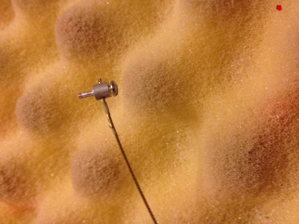
Oh, on top off all that, the holes in my missile rails are not anywhere near the centerline of the rail (marked with red line in photo). Looks like the tooling is off a bit.

Not impressed :-(
Regards,
Jim
BTW: 1000th post in this thread. Thanks to you Gripen lovers for making it a success!!!
Not impressed :-(
Regards,
Jim
BTW: 1000th post in this thread. Thanks to you Gripen lovers for making it a success!!!

