


JAS-39 Gripen Owners/Build Thread


 02-09-2015, 12:06 PM
#1102

On the full scale Gripen, the cockpit air conditioning system has two ducts which exit at the transition between the canopy and the dorsal. In the kit, this region has been molded as a flat bulkhead (naturally) but this leaves a lot to be desired.
I cut away fiberglass and molding fillets, and used balsa sheeting glued to the dorsal and spine as a mold. By laying up a few layers of glass cloth & resin on the inside, the dorsal deck and spine were extended into the cutout. The ducts themselves were made by carving a 1" long balsa block to shape and using it to make a silicon mold. From that, the two ducts were molded and installed. The ducts really improve the scale fidelity of the model.


Regards,
Jim
I cut away fiberglass and molding fillets, and used balsa sheeting glued to the dorsal and spine as a mold. By laying up a few layers of glass cloth & resin on the inside, the dorsal deck and spine were extended into the cutout. The ducts themselves were made by carving a 1" long balsa block to shape and using it to make a silicon mold. From that, the two ducts were molded and installed. The ducts really improve the scale fidelity of the model.
Regards,
Jim
Last edited by rcjets_63; 02-09-2015 at 01:17 PM.
02-09-2015, 12:37 PM
#1104
The build is progressing and I've split my time working on items all over the model. The upside of that is there is lots of variety and you don't get bored. The downside is that by working on everything, you finish nothing. Here's what I've been doing:
- The new wingtip pylon plug is well underway and I just have to shape the sensor pads at each end before I can lay up the mold. Dad's router table and wide assortment of router bits came in handy particularly to cut the curved inboard side and the top/bottom faces which taper outboard.
- My hydraulic system for the landing gear is on it's way back from Austria where it was upgraded by adding a bleed fitting to the accumulator.
- The tires have been molded and installed on the nose wheel and main gear rims. I should receive them by the end of the week.
- I ground out the big globs of glue that were in the fuselage at the wing roots to hold the anti-rotation pins and replaced these with wooden blocks and retaining bolts.
- The geometry for the main gear door cylinder is underway and I'll be able to finalize that once the cylinders arrive from Dreamworks this week.
- The clunk and vent were installed in the fuel tank. An elbow-shaped vent fitting was Hysol'd to the top front of the tank and points rearwards as the vent line will run along the spine and to the external vent at the scale location in the right wing root. I modified a Dreamworks overflow vent fitting by filing it flat. There is just enough room in the wing root to install the fitting. The final installation will have the fitting mounted to a piece of G-10 glued inside the wingroot with the top of the fitting filed flush with the lower wingskin per the full scale.
- The IFF antenna located behind the nose gear door, the UHF antenna ahead of the nose gear door, and the strakes just inboard of the canards were all made & installed
- 0.010 thick G-10 was used to fill in the gap between the wing and aileron on the underside of the wing. The gap was due to the lower wingskin being cut away at the factory to allow to allow the stock aileron (with live hinge at top) to deflect downwards.
- I started filling in all the incorrect screw heads and panel lines on the upper fuselage. Two-part spot putty and two coats of primer makes them disappear. Screw head and panel details in the correct locations will be added later
- The fuselage mold seams were all sanded, filled, resanded, refilled, resanded and are ready for paint
Here are a few pics:


Regards,
Jim
- The new wingtip pylon plug is well underway and I just have to shape the sensor pads at each end before I can lay up the mold. Dad's router table and wide assortment of router bits came in handy particularly to cut the curved inboard side and the top/bottom faces which taper outboard.
- My hydraulic system for the landing gear is on it's way back from Austria where it was upgraded by adding a bleed fitting to the accumulator.
- The tires have been molded and installed on the nose wheel and main gear rims. I should receive them by the end of the week.
- I ground out the big globs of glue that were in the fuselage at the wing roots to hold the anti-rotation pins and replaced these with wooden blocks and retaining bolts.
- The geometry for the main gear door cylinder is underway and I'll be able to finalize that once the cylinders arrive from Dreamworks this week.
- The clunk and vent were installed in the fuel tank. An elbow-shaped vent fitting was Hysol'd to the top front of the tank and points rearwards as the vent line will run along the spine and to the external vent at the scale location in the right wing root. I modified a Dreamworks overflow vent fitting by filing it flat. There is just enough room in the wing root to install the fitting. The final installation will have the fitting mounted to a piece of G-10 glued inside the wingroot with the top of the fitting filed flush with the lower wingskin per the full scale.
- The IFF antenna located behind the nose gear door, the UHF antenna ahead of the nose gear door, and the strakes just inboard of the canards were all made & installed
- 0.010 thick G-10 was used to fill in the gap between the wing and aileron on the underside of the wing. The gap was due to the lower wingskin being cut away at the factory to allow to allow the stock aileron (with live hinge at top) to deflect downwards.
- I started filling in all the incorrect screw heads and panel lines on the upper fuselage. Two-part spot putty and two coats of primer makes them disappear. Screw head and panel details in the correct locations will be added later
- The fuselage mold seams were all sanded, filled, resanded, refilled, resanded and are ready for paint
Here are a few pics:
Regards,
Jim

 02-11-2015, 09:48 AM
#1108
Thanks guys for the kind words; I can't wait to have this plane finished and in the air. It will fly at Top Gun at the end of April, but I will spend from then until the beginning of August (when it has to be shipped to Germany) adding scale details.
In the mean time, I took some pics of the various items that have been keeping me busy:
Here is the strobe light at the top rear of the fin. A wood block was glued to the aft side of the fairing and sanded to shape to match the full scale. The top of the fairing where the light is mounted was sanded (to the angle shown by the red line in the pic) to match the full scale


I got the curvature of the skin over the Sunstrand APU blister shaped correctly to match the full scale.


I ground out the blobs of resin/microballons and installed wooden blocks to receive the anti-rotation pins from the wings. The front block is drilled/tapped for a counterbored 4-40 SHCS. The aft block receives a 10-32 set screw (which takes the same wrench size as a 4-40 SHCS) for convenience. The modified Dreamworks vent fitting (installed at the scale location for the fuel dump valve) can be seen in the photos of the aft block.


The Jet Tech fuel tank was plumbed as shown below. A Dubro heavy clunk was drilled out and a 3/16" brass tube soldered in place. An elbow fitting was Hysol'd to the top of the tank to point rearwards.


In order to create a clear path along the top of the fuselage for routing the various tubes and cables to the tail, a hole had to be made through the top of the former in front of the wing tubes. I wish I had noticed this problem earlier as it would have been a lot easier to cut the hole before I glued the rear tank mount and main gear cylinder sub-formers in place. As such, it isn't the greatest looking grinding job, but it will have to do.

I did scale hinging of the ailerons (rather than the factory live hinging) and was left with a gap in the bottom surface of the wing in front of the aileron. The aileron lower hinge fairing molded into the wing surface isn't in the right location and doesn't have the right shape and size so it was sanded off. The gap was filled with two pieces of 0.010" thick G-10. It's hard to see the edges of the G-10 in the photo so I outlined the pieces in red dashed lines:

The rudder servo sits directly over the exhaust pipe where it can be exposed to high temperatures. As such, I enclosed the rudder servo and installed a heat shield made from .010 thick G-10. A cermanic blanket will be RTV'd over the G-10. I also put a lite-ply cover plate over the slot in the rudder (forward of the servo) to prevent heat from rising into the fin root where the servo and lighting wires are routed. You can see the rear 2-56 SH screw holding the cover plate in place.

In the mean time, I took some pics of the various items that have been keeping me busy:
Here is the strobe light at the top rear of the fin. A wood block was glued to the aft side of the fairing and sanded to shape to match the full scale. The top of the fairing where the light is mounted was sanded (to the angle shown by the red line in the pic) to match the full scale
I got the curvature of the skin over the Sunstrand APU blister shaped correctly to match the full scale.
I ground out the blobs of resin/microballons and installed wooden blocks to receive the anti-rotation pins from the wings. The front block is drilled/tapped for a counterbored 4-40 SHCS. The aft block receives a 10-32 set screw (which takes the same wrench size as a 4-40 SHCS) for convenience. The modified Dreamworks vent fitting (installed at the scale location for the fuel dump valve) can be seen in the photos of the aft block.
The Jet Tech fuel tank was plumbed as shown below. A Dubro heavy clunk was drilled out and a 3/16" brass tube soldered in place. An elbow fitting was Hysol'd to the top of the tank to point rearwards.
In order to create a clear path along the top of the fuselage for routing the various tubes and cables to the tail, a hole had to be made through the top of the former in front of the wing tubes. I wish I had noticed this problem earlier as it would have been a lot easier to cut the hole before I glued the rear tank mount and main gear cylinder sub-formers in place. As such, it isn't the greatest looking grinding job, but it will have to do.
I did scale hinging of the ailerons (rather than the factory live hinging) and was left with a gap in the bottom surface of the wing in front of the aileron. The aileron lower hinge fairing molded into the wing surface isn't in the right location and doesn't have the right shape and size so it was sanded off. The gap was filled with two pieces of 0.010" thick G-10. It's hard to see the edges of the G-10 in the photo so I outlined the pieces in red dashed lines:
The rudder servo sits directly over the exhaust pipe where it can be exposed to high temperatures. As such, I enclosed the rudder servo and installed a heat shield made from .010 thick G-10. A cermanic blanket will be RTV'd over the G-10. I also put a lite-ply cover plate over the slot in the rudder (forward of the servo) to prevent heat from rising into the fin root where the servo and lighting wires are routed. You can see the rear 2-56 SH screw holding the cover plate in place.
Last edited by rcjets_63; 02-11-2015 at 02:03 PM.
02-12-2015, 02:04 PM
#1110

Join Date: Oct 2003
Location: Riedt, SWITZERLAND
Posts: 28
Likes: 0
Received 0 Likes
on
0 Posts
Hello together,
it's nice to see how other build this airplane to perfection.
It's a couple of years ago when i've build mine, but I can still rember some problems I had.
Please have a eye on your airflow to the turbine. In my first configuration the fuelcell was to big and did blog the airflow to the turbine. The turbine got the hot air from the rear and did run without a problem, but the hydraulic lines to the air brake cylinder didn't withstand the hot air from the rear. I was lucky that this happend shortly after take off and the gear was still extended when a smoke trail showed me that I've a leak in the hydraulic system.
This can happen if you close the main gear doors when gear is extended. I made a smaller fuel cell (app. 1 1/2 GAL.) that did not restrict the airflow to the turbine.
I disconnected the airbrakes until i did know that the lines will withstand.
greetings
Martin
02-12-2015, 04:18 PM
#1111
Martin,
Thank you very much for your input. Please feel free to voice any comments and concerns as I would value your experience gained from your Gripen.
Yes, the fuel tank certainly does partially obscure that airflow and I was planning on watching it carefully during the first few engine runs later this month. If need be, I will make a smaller main tank and add a couple of small saddle tanks.
As for the speed brakes, I have decided to use a dedicated compressed air system rather than hydraulics. The gear cylinders have to be hydraulic in order to lock, but the door cylinders can either be hydraulic or air. I'm not sure if the brake system has to be hydraulic or if it can be air. It might seem like a bit of a waste to have both systems, but air tanks have little weight, the small diameter air line is lighter than the hydraulic line, and the consequences of an air leak are much less than a hydraulic leak. Also, I have lots of experience with air systems and components and none with hydraulics (at least in models).
Regards,
Jim
Last edited by rcjets_63; 02-12-2015 at 04:43 PM.
02-16-2015, 12:33 PM
#1112
I had a great weekend at the Monster Energy Invitational Jet Jam in Coachella (Palm Springs) CA on Friday & Saturday. While I was gone, a few items arrived in the mail including the main gear door cylinders from Dreamworks. I worked a bit on the geometry and found a simple/easy installation as shown.
The selected door cylinders are Ultra Precision 7/16" diameter bore x 2" stroke with 4-40 threads on the end of the rod. A Dubro 4-40 plastic ball end screws onto the rod and is bolted the between two .060" thick G-10 control horns. The forward G-10 control horn is glued to the door liner while the rear piece of G-10, which is both a control horn and the door center hinge, fits through a slot in the door liner and is glued to the inside surface of the door. The G-10 pieces are drilled for a 4-40 bolt with the drill hole being 1-3/8" from the hinge line.
The door cylinders were fitted to Ultra Precision cylinder mounts (also available from Dreamworks) which were screwed to brackets made from 1/4" plywood. The brackets were located & glued to the fuel tank such that, when fully extended, the doors are fully open to the required angle to clear the tire as it retracts. I found that I didn't have quite enough clearance between the rod and the scissor link and there was some interference between them as the door closed. This was solved by trimming the bottom off the plywood bracket as shown by the red line in the photo.


Yes, that is a bit of a funky shape for the control horn, but it is pretty close to scale. I can fine tune the shape and add the gussets later if I really want add scale details to the bracket. In the mean time, it is good enough to fly.
I also received a parcel notice from the post office which should either be the paint and dry transfers from Tailor-Made Decals (thanks Rollie) or the hydraulic system which I sent back to the manufacturer in Austria for an upgrade. It's Presidents' Day so I shall have to wait until tomorrow to discover which. In the mean time, enjoy your holiday.
Regards,
Jim
Taking the geometry into account, the cylinder holds the door closed with ~350 in-lbs of torque at 120 psi.
The selected door cylinders are Ultra Precision 7/16" diameter bore x 2" stroke with 4-40 threads on the end of the rod. A Dubro 4-40 plastic ball end screws onto the rod and is bolted the between two .060" thick G-10 control horns. The forward G-10 control horn is glued to the door liner while the rear piece of G-10, which is both a control horn and the door center hinge, fits through a slot in the door liner and is glued to the inside surface of the door. The G-10 pieces are drilled for a 4-40 bolt with the drill hole being 1-3/8" from the hinge line.
The door cylinders were fitted to Ultra Precision cylinder mounts (also available from Dreamworks) which were screwed to brackets made from 1/4" plywood. The brackets were located & glued to the fuel tank such that, when fully extended, the doors are fully open to the required angle to clear the tire as it retracts. I found that I didn't have quite enough clearance between the rod and the scissor link and there was some interference between them as the door closed. This was solved by trimming the bottom off the plywood bracket as shown by the red line in the photo.
Yes, that is a bit of a funky shape for the control horn, but it is pretty close to scale. I can fine tune the shape and add the gussets later if I really want add scale details to the bracket. In the mean time, it is good enough to fly.
I also received a parcel notice from the post office which should either be the paint and dry transfers from Tailor-Made Decals (thanks Rollie) or the hydraulic system which I sent back to the manufacturer in Austria for an upgrade. It's Presidents' Day so I shall have to wait until tomorrow to discover which. In the mean time, enjoy your holiday.
Regards,
Jim
Taking the geometry into account, the cylinder holds the door closed with ~350 in-lbs of torque at 120 psi.
Last edited by rcjets_63; 02-16-2015 at 12:38 PM.
02-18-2015, 09:34 PM
#1113
Inner Main Gear Doors
The inner main gear doors in my kit are somewhat problematic. First of all, they are too small (and the main doors are too big). About 1/4" needed to be trimmed off the rear curved edge of the main door to prevent interference between the door and the gear strut. By doing the trim, an unsightly 1/4" gap results between the main and inner doors. The other issues with the inner doors are that the flanges around the outside are too thick to fit into the recesses around the door cutout and overall are are just a poor fit.
As such, it was pretty apparent that I'd have to mold my own inner gear doors. Like everything else I've had to mold to replace parts of this kit, it is a lot of work, but it is worth it.
To mold the inner doors, I used the same technique as when I molded the new canopy frame. The fuselage serves as the plug with the cutout for the inner doors filled in with pieces of blue foam and sanded to shape. A bit of spackling paste was added to fill in the any gaps and sanded smooth. That produces the male "plug" which is then used to make the female mold.
Rather than using a release agent and laying up the mold directly on the fuselage, I taped a couple of pieces of Saran Wrap in place. A light misting of 3M 77 spray keeps the Saran Wrap from moving when the fiberglass cloth/resin layers are applied. The layup was 3 layers of 4 oz and 3 layers of 10 oz cloth.


Regards,
Jim
The inner main gear doors in my kit are somewhat problematic. First of all, they are too small (and the main doors are too big). About 1/4" needed to be trimmed off the rear curved edge of the main door to prevent interference between the door and the gear strut. By doing the trim, an unsightly 1/4" gap results between the main and inner doors. The other issues with the inner doors are that the flanges around the outside are too thick to fit into the recesses around the door cutout and overall are are just a poor fit.
As such, it was pretty apparent that I'd have to mold my own inner gear doors. Like everything else I've had to mold to replace parts of this kit, it is a lot of work, but it is worth it.
To mold the inner doors, I used the same technique as when I molded the new canopy frame. The fuselage serves as the plug with the cutout for the inner doors filled in with pieces of blue foam and sanded to shape. A bit of spackling paste was added to fill in the any gaps and sanded smooth. That produces the male "plug" which is then used to make the female mold.
Rather than using a release agent and laying up the mold directly on the fuselage, I taped a couple of pieces of Saran Wrap in place. A light misting of 3M 77 spray keeps the Saran Wrap from moving when the fiberglass cloth/resin layers are applied. The layup was 3 layers of 4 oz and 3 layers of 10 oz cloth.
Regards,
Jim
Last edited by rcjets_63; 02-19-2015 at 07:29 AM.
02-18-2015, 10:42 PM
#1114
Fin Details
The full scale aircraft I'm modeling (CAF #3-9245 in the scheme from the 2010 NATO Tiger Meet) used graphics printed on adhesive backed mylar applied to the canards and fin. Here are some pics of the mylars being applied to the aircraft.


I managed to obtain a copy of the actual graphics file used to print the mylars for the full scale aircraft. That was quite a coup so it is only appropriate to get the mylars printed at the correct scale and align/install them to perfectly match the aircraft. The problem is, I have no idea what scale their printer was set to. As such, it was quite a case of trial and error to figure out the correct scale. I'd make a SWAG (scientific wild *ss'd guess), print them on paper, do a trial installation, make a correction to the scale, and repeat. There were several iterations. Eventually I sorted it out as follows:
To get the scale factor, I needed at least one (and preferably more) pairs of features that are as far away as possible from each other on the fin. You then adjust the printer scale until the graphics on the mylar line up with the features on the fin. Here is a marked up photo of the full scale showing how the mylar aligns with a variety of features on the fin.

Point 1 - The bottom of the middle hinge is just above a highlight on the claw bone
Point 2 - The top of the white outline around the 2 aligns with a panel line
Point 3 - The curved portion of the 2 comes quite close to the leading edge of the fin
Point 4 - The backup pitot tube centerline aligns with where the sabre-tooth enters the skull
Point 5 - The corner of the upper rudder hinge almost touches the outline of the skull
Point 6 - The top of the EM sensor fairing aligns with a feature at the nasal opening of the skull
Point 7 - The lower edge of the rudder aligns with the end of a highlight on the claw bone
Point 8 - The panel line is just below a crack in the sabre-tooth
Point 9 - The top of the rudder aligns with a highlighted bump on the crown of the skull
While it is possible to determine the print scale using only one pair of features, this isn't advisable because it is entirely possible that one of the features chosen was not molded in exactly the right place on the model. As such, I wanted to checked the alignment at all the points listed above. I'll never know what feature the static judge is going to choose so everything needs to align.
Using the points listed above, I added some red layout lines to a new layer in the graphics file. The color settings on the printer I used were off a bit (not enough black) so the paper print looks a bit funky (Once I have the scale and alignment determined using paper prints, "Electro" Bob Belluomini will be printing the final versions on mylar and he will have his equipment, like his planes, in top form so they will match the full scale prints).

After a few iterations, I finally figured out the scale factor needed so that the points line up.


The edge of the white outline around the 2 lines up with the panel line, the edge of the 2 is close to the leading edge, the pitot tube centerline aligns with the tooth base, the top of the rudder and upper hinge align, and the bottom of the rudder lines up as well. Since features align on the front, back, top, and bottom of the fin, I figure I've got a pretty good match except......if you look in the second photo above, you'll see that the top of the EM sensor fairing is about 1/8" above the feature above the nasal opening of the skull. The model's EM fairing was molded 1/8" too high (also the blend doesn't extend quite far enough rearward. I'll add that to the list of issues to fix. I really want a 10 for markings from the static judges.
Now that I've got the print scaled and aligned, I can use it to check any other points of interest on the model. One thing that was obviously wrong was the location of the rectangular formation lights and the vent near the fin leading edge. I cropped a photo of the full scale in this region and adjusted the print scale until it matched the overall fin print. Then the cropped photo was positioned to align with the overall print, and the formation light and vent outlines were cut out and marked on the model. The front and back edges of the vent as molded by Airworld were in the correct locations but the top/bottom edges were obviously wrong. Some filler compound was used to correct the upper edge while the lower edge was corrected by grinding/sanding the molded cutout. There wasn't quite enough material thickness at the bottom forward corner so I sanded through the skin. This can be easily fixed by laminating a layer of cloth/resin to the inside of he fin and finishing the exterior with some putty.


Tomorrow is a big day, the custom rims and tires are due to arrive so I will fit them to the model tomorrow night. My hydraulic system arrived the other day from Austria, and my order of hydraulic fluid also is being delivered tomorrow. I'll post some more pics tomorrow night.e
Regards,
Jim
The full scale aircraft I'm modeling (CAF #3-9245 in the scheme from the 2010 NATO Tiger Meet) used graphics printed on adhesive backed mylar applied to the canards and fin. Here are some pics of the mylars being applied to the aircraft.
I managed to obtain a copy of the actual graphics file used to print the mylars for the full scale aircraft. That was quite a coup so it is only appropriate to get the mylars printed at the correct scale and align/install them to perfectly match the aircraft. The problem is, I have no idea what scale their printer was set to. As such, it was quite a case of trial and error to figure out the correct scale. I'd make a SWAG (scientific wild *ss'd guess), print them on paper, do a trial installation, make a correction to the scale, and repeat. There were several iterations. Eventually I sorted it out as follows:
To get the scale factor, I needed at least one (and preferably more) pairs of features that are as far away as possible from each other on the fin. You then adjust the printer scale until the graphics on the mylar line up with the features on the fin. Here is a marked up photo of the full scale showing how the mylar aligns with a variety of features on the fin.
Point 1 - The bottom of the middle hinge is just above a highlight on the claw bone
Point 2 - The top of the white outline around the 2 aligns with a panel line
Point 3 - The curved portion of the 2 comes quite close to the leading edge of the fin
Point 4 - The backup pitot tube centerline aligns with where the sabre-tooth enters the skull
Point 5 - The corner of the upper rudder hinge almost touches the outline of the skull
Point 6 - The top of the EM sensor fairing aligns with a feature at the nasal opening of the skull
Point 7 - The lower edge of the rudder aligns with the end of a highlight on the claw bone
Point 8 - The panel line is just below a crack in the sabre-tooth
Point 9 - The top of the rudder aligns with a highlighted bump on the crown of the skull
While it is possible to determine the print scale using only one pair of features, this isn't advisable because it is entirely possible that one of the features chosen was not molded in exactly the right place on the model. As such, I wanted to checked the alignment at all the points listed above. I'll never know what feature the static judge is going to choose so everything needs to align.
Using the points listed above, I added some red layout lines to a new layer in the graphics file. The color settings on the printer I used were off a bit (not enough black) so the paper print looks a bit funky (Once I have the scale and alignment determined using paper prints, "Electro" Bob Belluomini will be printing the final versions on mylar and he will have his equipment, like his planes, in top form so they will match the full scale prints).
After a few iterations, I finally figured out the scale factor needed so that the points line up.
The edge of the white outline around the 2 lines up with the panel line, the edge of the 2 is close to the leading edge, the pitot tube centerline aligns with the tooth base, the top of the rudder and upper hinge align, and the bottom of the rudder lines up as well. Since features align on the front, back, top, and bottom of the fin, I figure I've got a pretty good match except......if you look in the second photo above, you'll see that the top of the EM sensor fairing is about 1/8" above the feature above the nasal opening of the skull. The model's EM fairing was molded 1/8" too high (also the blend doesn't extend quite far enough rearward. I'll add that to the list of issues to fix. I really want a 10 for markings from the static judges.
Now that I've got the print scaled and aligned, I can use it to check any other points of interest on the model. One thing that was obviously wrong was the location of the rectangular formation lights and the vent near the fin leading edge. I cropped a photo of the full scale in this region and adjusted the print scale until it matched the overall fin print. Then the cropped photo was positioned to align with the overall print, and the formation light and vent outlines were cut out and marked on the model. The front and back edges of the vent as molded by Airworld were in the correct locations but the top/bottom edges were obviously wrong. Some filler compound was used to correct the upper edge while the lower edge was corrected by grinding/sanding the molded cutout. There wasn't quite enough material thickness at the bottom forward corner so I sanded through the skin. This can be easily fixed by laminating a layer of cloth/resin to the inside of he fin and finishing the exterior with some putty.
Tomorrow is a big day, the custom rims and tires are due to arrive so I will fit them to the model tomorrow night. My hydraulic system arrived the other day from Austria, and my order of hydraulic fluid also is being delivered tomorrow. I'll post some more pics tomorrow night.e
Regards,
Jim
Last edited by rcjets_63; 02-18-2015 at 11:02 PM.
02-20-2015, 09:45 PM
#1115
The scale rims and tires arrived and they are gorgeous!!!!! I couldn't wait to install them on the plane. Sooooo much better than the Airworld supplied wheels!


I received the hydraulic system back from MTH in Austria the other day. They recommend using Castrol Carelube HTG 32 hydraulic oil. This is a biodegradable 32 centistokes (ISO 32, SAE 10W) viscosity oil that is readily available in Europe but not here in North America. The AW Gripen thread suggested using a 22 centistokes (ISO 22) oil instead particularly when it is cold and the oil thickens. Cold isn't much of a problem in Phoenix and I was having trouble finding a supplier who would sell me less than 5 gallons so I just went to McMaster-Carr and ordered a gallon of Mobil DTE 24 Light which is a 10W oil.
The hydraulic system is now equipped with a bleed port integrated into the oil return line (on the right in the photo below); it makes bleeding the air out of the tank a lot easier.

You'll need a big syringe that you can connect 4mm tubing. I had a couple of 15 ml syringes (left over from my wild days, yeah, that's my story) so it took a while to fill the tank. I'll pick up a 50 ml or 100 ml from the pharmacy next time. I connected the cylinders and a two way directional control valve and did some test runs on the bench. Here's a video:
https://www.youtube.com/watch?v=R2fvANvVy0Y&feature=youtu.be Regards,
Jim
I received the hydraulic system back from MTH in Austria the other day. They recommend using Castrol Carelube HTG 32 hydraulic oil. This is a biodegradable 32 centistokes (ISO 32, SAE 10W) viscosity oil that is readily available in Europe but not here in North America. The AW Gripen thread suggested using a 22 centistokes (ISO 22) oil instead particularly when it is cold and the oil thickens. Cold isn't much of a problem in Phoenix and I was having trouble finding a supplier who would sell me less than 5 gallons so I just went to McMaster-Carr and ordered a gallon of Mobil DTE 24 Light which is a 10W oil.
The hydraulic system is now equipped with a bleed port integrated into the oil return line (on the right in the photo below); it makes bleeding the air out of the tank a lot easier.
You'll need a big syringe that you can connect 4mm tubing. I had a couple of 15 ml syringes (left over from my wild days, yeah, that's my story) so it took a while to fill the tank. I'll pick up a 50 ml or 100 ml from the pharmacy next time. I connected the cylinders and a two way directional control valve and did some test runs on the bench. Here's a video:
https://www.youtube.com/watch?v=R2fvANvVy0Y&feature=youtu.be Regards,
Jim
 02-22-2015, 10:22 PM
#1117
Hydraulic Landing Gear System
It was a full day in the shop with progress made on several fronts. I have sent my fuel tank back to Jet Tech for be reduced in height by an inch. This will better allow air to flow through the fuselage. Many thanks to Martin (festus01) for the warning/suggestion.

With the tank removed, I took the opportunity to install the hydraulic cylinders for the main landing gear. Rather than use the pins & E-clips provided in the kit, I substituted 4mm SHCS and nylon insert safety nuts to mount the cylinders to their upper swivel bracket. I think this was a lot easier than trying to push on an E-clip down in the depths of the plane and you don't have to worry about an safety nut coming off. Regular 4mm tubing and Festo connectors were used to for the hydraulic lines which route on each side of the tank. The disconnects make it a lot easier to bleed the system of any air and also allow for easy removal of a cylinder for maintenance. Similarly, the nose gear cylinder lines also have nearby Festo unions and the lines are routed through a hole drilled through the plywood longeron just low enough to miss the cockpit side piece. Note the orientation of the 90 degree fittings on the cylinders to improve the routing of the 4mm lines.


Here is a video of the landing gear retraction/extension test. I will mount the hydraulic pack after I've completed a few more items in the build.
https://www.youtube.com/watch?v=901P-y4HkB0 The retraction took 14 seconds which is way too slow. The extension was 9 seconds which is also too slow (those times need to be cut in half). ISO 32 hydraulic fluid was used but I will switch to a less viscous ISO 22 oil if I can find a supplier who will sell me less than 5 gallons. Jet Team USA team mate Scott Harris suggested a ester refrigerant oil which is ISO 22 and sold in 8oz cans. I shall check to see if it is compatible with the various seals/components in the hydraulic system.
Nose Gear Doors
I also worked a bit on the nose gear doors. The air lines for the left & right rear doors were routed as per the photo below. The forward door was a poor fit (flanges too thick) and the inner skin wasn't very scale so ground off the inner skin and laminated a couple of layers of 1/16" balsa sanded to the scale shape and glassed the skin.


Once I receive the taxi light housing (from Details for Scale) , the thru hole for the light will be cut and the light housing mounted to the inside of the door.
The new scale wingtip pylon plug is also coming along. I didn't have a very good pic of the curvature (as seen from top/bottom) of the pylon at the front and back so I contacted a friend who snapped the needed pics of a Gripen in the hanger. I'll post some pics of the plug when it is finished.


Regards,
Jim
It was a full day in the shop with progress made on several fronts. I have sent my fuel tank back to Jet Tech for be reduced in height by an inch. This will better allow air to flow through the fuselage. Many thanks to Martin (festus01) for the warning/suggestion.
With the tank removed, I took the opportunity to install the hydraulic cylinders for the main landing gear. Rather than use the pins & E-clips provided in the kit, I substituted 4mm SHCS and nylon insert safety nuts to mount the cylinders to their upper swivel bracket. I think this was a lot easier than trying to push on an E-clip down in the depths of the plane and you don't have to worry about an safety nut coming off. Regular 4mm tubing and Festo connectors were used to for the hydraulic lines which route on each side of the tank. The disconnects make it a lot easier to bleed the system of any air and also allow for easy removal of a cylinder for maintenance. Similarly, the nose gear cylinder lines also have nearby Festo unions and the lines are routed through a hole drilled through the plywood longeron just low enough to miss the cockpit side piece. Note the orientation of the 90 degree fittings on the cylinders to improve the routing of the 4mm lines.
Here is a video of the landing gear retraction/extension test. I will mount the hydraulic pack after I've completed a few more items in the build.
https://www.youtube.com/watch?v=901P-y4HkB0 The retraction took 14 seconds which is way too slow. The extension was 9 seconds which is also too slow (those times need to be cut in half). ISO 32 hydraulic fluid was used but I will switch to a less viscous ISO 22 oil if I can find a supplier who will sell me less than 5 gallons. Jet Team USA team mate Scott Harris suggested a ester refrigerant oil which is ISO 22 and sold in 8oz cans. I shall check to see if it is compatible with the various seals/components in the hydraulic system.
Nose Gear Doors
I also worked a bit on the nose gear doors. The air lines for the left & right rear doors were routed as per the photo below. The forward door was a poor fit (flanges too thick) and the inner skin wasn't very scale so ground off the inner skin and laminated a couple of layers of 1/16" balsa sanded to the scale shape and glassed the skin.
Once I receive the taxi light housing (from Details for Scale) , the thru hole for the light will be cut and the light housing mounted to the inside of the door.
The new scale wingtip pylon plug is also coming along. I didn't have a very good pic of the curvature (as seen from top/bottom) of the pylon at the front and back so I contacted a friend who snapped the needed pics of a Gripen in the hanger. I'll post some pics of the plug when it is finished.
Regards,
Jim
02-23-2015, 01:37 PM
#1118
Join Date: Oct 2003
Location: Riedt, SWITZERLAND
Posts: 28
Likes: 0
Received 0 Likes
on
0 Posts
Hello Jim,
I've used also the ISO 22 oil, but I used the Festo tube with 6mm outer dia for the main gear, only a short sequence after a 6 to 4 mm Y to each cylinder.
The reference air pressure is app. 8bar. Pump voltage 7.2V.
I hade a faster moving, and the pump sequence is longer, only 2 pump sequence with very short pause between to bring the gear up or down.
In your video, the pump sequence is very short, that means pump get very fast the reference pressure, but it needs a longer time until pressure drops down to start pump again. --> to much drag in the lines.
Regards
Martin
02-24-2015, 06:22 AM
#1120
Martin & Sebastian,
Thanks for the input. Yes, I didn't like the pump sequencing as often as it did. I will change the lines to 6mm and change the oil to ISO22. Fortunately, I found a supply of ISO22 hydraulic oil on Amazon (available in a quart or gallon) in picture below. If it is still too slow, I will switch to food grade mineral oil (which is advertised as having a viscosity as low as 7 centistokes.

Regards,
Jim
Thanks for the input. Yes, I didn't like the pump sequencing as often as it did. I will change the lines to 6mm and change the oil to ISO22. Fortunately, I found a supply of ISO22 hydraulic oil on Amazon (available in a quart or gallon) in picture below. If it is still too slow, I will switch to food grade mineral oil (which is advertised as having a viscosity as low as 7 centistokes.
Regards,
Jim
02-24-2015, 09:24 AM
#1121
Turbine and Fuel System Installation
My Kingtech K210 arrived last night (love that new turbine smell) so I set to work doing the install once Pavel (my Czech pilot) took it out for a spin. I guess he's tired of waiting around the shop for me to finish his ride and just wants to fly.

The install is pretty straight forward with just some minor trimming of the turbine mounting rails rails needed to clear the mounting straps. I temporarily removed the light ply longeron to give access to the base of the fin in order to add a couple of layers of 4 oz cloth at the fin vents (as needed per post #1114 above). I don't plan on using a bypass (though I may do a bit of a shroud, if needed) so, after reinstalling the longeron, I added a ceramic blanket to protect the longeron and the lighting and servo wires. After that, it was a simple matter of installing the turbine and Tamjets pipe with #8 and #4 socket head screws, respectively.


The routing of the fuel line, the 3-conductor starter/glow power line, and the signal cable was quite straightforward. I was able to route the lines through the holes previously cut in the wing and hydraulic swivel mount formers so that they will route along the dorsal "spine" and forward through the main landing gear bay and into the area between the inlets where the ECU will be installed.


Next was the fuel system with the installation of the CAT UAT generously provided by GBR Jets (sponsors to Jet Team USA to the 2015 JWM) and the fuel pump. These were installed in the area between the two longerons between the main landing gear cutouts. Note that I added a sub-former to tie the longerons together at the drag link pivot blocks. A slot was cut through the former at the front of the main landing gear bay to route the 4mm fuel line and fuel pump wires, along with the CAT fill line.

Regards,
Jim
My Kingtech K210 arrived last night (love that new turbine smell) so I set to work doing the install once Pavel (my Czech pilot) took it out for a spin. I guess he's tired of waiting around the shop for me to finish his ride and just wants to fly.
The install is pretty straight forward with just some minor trimming of the turbine mounting rails rails needed to clear the mounting straps. I temporarily removed the light ply longeron to give access to the base of the fin in order to add a couple of layers of 4 oz cloth at the fin vents (as needed per post #1114 above). I don't plan on using a bypass (though I may do a bit of a shroud, if needed) so, after reinstalling the longeron, I added a ceramic blanket to protect the longeron and the lighting and servo wires. After that, it was a simple matter of installing the turbine and Tamjets pipe with #8 and #4 socket head screws, respectively.
The routing of the fuel line, the 3-conductor starter/glow power line, and the signal cable was quite straightforward. I was able to route the lines through the holes previously cut in the wing and hydraulic swivel mount formers so that they will route along the dorsal "spine" and forward through the main landing gear bay and into the area between the inlets where the ECU will be installed.
Next was the fuel system with the installation of the CAT UAT generously provided by GBR Jets (sponsors to Jet Team USA to the 2015 JWM) and the fuel pump. These were installed in the area between the two longerons between the main landing gear cutouts. Note that I added a sub-former to tie the longerons together at the drag link pivot blocks. A slot was cut through the former at the front of the main landing gear bay to route the 4mm fuel line and fuel pump wires, along with the CAT fill line.
Regards,
Jim
02-24-2015, 11:31 AM
#1122
Here is a video of a landing gear retraction/extension test of a full scale Gripen. This will be useful to get the timing.
https://www.youtube.com/watch?v=xsjYI9JBUyA Regards,
Jim
https://www.youtube.com/watch?v=xsjYI9JBUyA Regards,
Jim
02-24-2015, 11:31 AM
#1123
Nose Door Linkage
I thought I'd take a break from the "innards" and work on the nose gear door linkage. I wanted to make it as scale as possible but recognized that this might not be possible because the geometry of the kit retracts is likely different from the full scale. Alas, I thought I'd try.
The first issue was to get the geometry. By cropping a side view picture of the full scale and importing it into Corel Draw at the right scale for the model, I was able to determine the size and location of the linkage brackets installed on the nose door. I traced the outline and made several templates of the brackets. The brackets on the doors have a U-shaped cross-section and capture the linkage rod end between their flanges as can be seen in the third photo.


I made the brackets from .030 thick G-10 and mounted them on the door per the dimensions above. Next came determining where the other end of the linkage would have to go in order that the door was open at the correct angle when the gear was down, and completely close the door when the gear was up. A piece of 4-40 threaded rod with a clevis at each end made an easy jig and I was able to quickly determine where the bracket on the strut had to go. Unfortunately, is noticeably higher than the full-scale because, as expected, the nose gear pivot point on the model doesn't match the full scale. Oh well. A slot was cut through the nose strut and a G-10 bracket was inserted through the slot and glued in place.

To make the linkage, I started with a set of Dubro 1/4 scale turnbuckles (Cat No 300) and a length of 1/8" brass tubing. The tubing was threaded on one end for the RH thread rod end. I ground the thread off the LH rod end and soldered it into the brass tubing. A bit of heat shrink was added to increase the diameter of the linkage on one end per the full scale. The rod ends were drilled for clearance holes and screwed in place with BVM button head screws.


With a bit of light grey paint on the heat shrink and some chrome paint on the brass, I'm hoping it will look pretty realistic (especially after I make the second linkage tomorrow night after the taxi light housing arrives).
Regards,
Jim.
I thought I'd take a break from the "innards" and work on the nose gear door linkage. I wanted to make it as scale as possible but recognized that this might not be possible because the geometry of the kit retracts is likely different from the full scale. Alas, I thought I'd try.
The first issue was to get the geometry. By cropping a side view picture of the full scale and importing it into Corel Draw at the right scale for the model, I was able to determine the size and location of the linkage brackets installed on the nose door. I traced the outline and made several templates of the brackets. The brackets on the doors have a U-shaped cross-section and capture the linkage rod end between their flanges as can be seen in the third photo.
I made the brackets from .030 thick G-10 and mounted them on the door per the dimensions above. Next came determining where the other end of the linkage would have to go in order that the door was open at the correct angle when the gear was down, and completely close the door when the gear was up. A piece of 4-40 threaded rod with a clevis at each end made an easy jig and I was able to quickly determine where the bracket on the strut had to go. Unfortunately, is noticeably higher than the full-scale because, as expected, the nose gear pivot point on the model doesn't match the full scale. Oh well. A slot was cut through the nose strut and a G-10 bracket was inserted through the slot and glued in place.
To make the linkage, I started with a set of Dubro 1/4 scale turnbuckles (Cat No 300) and a length of 1/8" brass tubing. The tubing was threaded on one end for the RH thread rod end. I ground the thread off the LH rod end and soldered it into the brass tubing. A bit of heat shrink was added to increase the diameter of the linkage on one end per the full scale. The rod ends were drilled for clearance holes and screwed in place with BVM button head screws.
With a bit of light grey paint on the heat shrink and some chrome paint on the brass, I'm hoping it will look pretty realistic (especially after I make the second linkage tomorrow night after the taxi light housing arrives).
Regards,
Jim.
Last edited by rcjets_63; 02-25-2015 at 02:27 PM.
02-25-2015, 02:20 PM
#1124
Further to post #1121, here's a pic of the ceramic heat blanket installed at the fin base to protect the rudder servo cable and lighting wires.

In looking at pics of the vent at the forward base of the fin, it appeared that the lower surface sloped down and outboard but I couldn't get a good idea of the angle from side view shots. I asked my buddy to send me some better photos of the vent (posted below). From the pics looking forward into the vent, you can see the angle of the vent lower surface.


It's also interesting how the left vent has a cutout in the front lower corner. This was quite the surprise to me as I'd never seen this before likely as the mylar fin cover is black in this area. However, on closer inspection of several photos of 9245, the cutout is indeed there.


Regards,
Jim
In looking at pics of the vent at the forward base of the fin, it appeared that the lower surface sloped down and outboard but I couldn't get a good idea of the angle from side view shots. I asked my buddy to send me some better photos of the vent (posted below). From the pics looking forward into the vent, you can see the angle of the vent lower surface.
It's also interesting how the left vent has a cutout in the front lower corner. This was quite the surprise to me as I'd never seen this before likely as the mylar fin cover is black in this area. However, on closer inspection of several photos of 9245, the cutout is indeed there.
Regards,
Jim
02-26-2015, 12:15 AM
#1125
Navigation & Strobe Lights
Light really brighten up a model (groan) so there was no question about adding them to this plane and I was in luck for making them as scale as possible. My company actually makes most of the lights for the full scale Gripen so it didn't take long to get a set of dimensioned drawings. I forwarded these to Dan Gill at Details for Scale and he CNC machined the molds for all the light housings and lenses.
The light system is one of the more noticeable differences between the JAS-39 A/B and the C/D variants. The A/B uses incandescent lights with colored lenses while the C/D uses colored LED's with clear lenses. Here are some pics of each. The strobe light on the tail is common to the A-D variants.


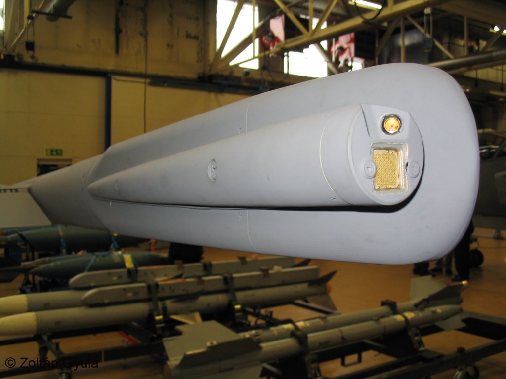

In case you are wondering, the little yellow round lights you see in the photos of the C/D LED lights are night vision lights used when flying with goggles.
The lights on the inboard side of the wingtip pylons are position lights (either white or green) that show the size of the plane. They can be selected in the cockpit and adjusted for brightness and whether to pulse or flash or turned on from the service panel for towing/maintenance at which point they are much dimmed. I have several thousand photos of the Gripen, and only in a couple of them are the lights on and, in those cases, the plane is on the ground with maintenance personnel at work. I've never seen a pic of these lights on when the plane is in the air. As such, I'm not going to install LED's on the wingtip pylon.
Here are some pics of the lights on the model. I first make sub-assemblies with short wire leads as it is a lot easier than wrestling with coils of wire on the bench. The left & right navigation lights were straight forward in that they glue directly to the side of the fuselage.


Continued in next post....
Regards,
Jim
Light really brighten up a model (groan) so there was no question about adding them to this plane and I was in luck for making them as scale as possible. My company actually makes most of the lights for the full scale Gripen so it didn't take long to get a set of dimensioned drawings. I forwarded these to Dan Gill at Details for Scale and he CNC machined the molds for all the light housings and lenses.
The light system is one of the more noticeable differences between the JAS-39 A/B and the C/D variants. The A/B uses incandescent lights with colored lenses while the C/D uses colored LED's with clear lenses. Here are some pics of each. The strobe light on the tail is common to the A-D variants.
In case you are wondering, the little yellow round lights you see in the photos of the C/D LED lights are night vision lights used when flying with goggles.
The lights on the inboard side of the wingtip pylons are position lights (either white or green) that show the size of the plane. They can be selected in the cockpit and adjusted for brightness and whether to pulse or flash or turned on from the service panel for towing/maintenance at which point they are much dimmed. I have several thousand photos of the Gripen, and only in a couple of them are the lights on and, in those cases, the plane is on the ground with maintenance personnel at work. I've never seen a pic of these lights on when the plane is in the air. As such, I'm not going to install LED's on the wingtip pylon.
Here are some pics of the lights on the model. I first make sub-assemblies with short wire leads as it is a lot easier than wrestling with coils of wire on the bench. The left & right navigation lights were straight forward in that they glue directly to the side of the fuselage.
Continued in next post....
Regards,
Jim
Last edited by rcjets_63; 02-26-2015 at 09:24 AM.