


JAS-39 Gripen Owners/Build Thread
 02-26-2015, 12:30 AM
#1126

Navigation & Strobe Lights - Continued
Continued from post on previous page.
The aft navigation lights were a bit tougher. There is an error in the Airworld kit in that the distance between the aft edge of the speed brakes and the forward edge of the engine nozzle is about 1/2" too short. The aft navigation lights fully occupy this space so I had no choice but to cut my scale lights short and reshape them as best as I could yet still have them blend correctly into the flare in the speed brakes. These lights sit on wedge shaped bases which were made from trailing edge balsa (which coincidentally had the right angle).


The strobe light near the top of the fin was also a bit of a challenge. To route the wire, I had to drill a hole in the aft end of the fin upper fairing and use a long reach drill to drill a hole through the fin spar. Fishing the wire was an exercise in patience, but I finally got it. The top of the fairing was sanded to the scale angle (the light isn't mounted level) and some Bondo added to build up the area to fit the light base and blended into the fairing.


The lenses for the lights will be added after the bases are detailed and the plane painted.
Regards,
Jim
Continued from post on previous page.
The aft navigation lights were a bit tougher. There is an error in the Airworld kit in that the distance between the aft edge of the speed brakes and the forward edge of the engine nozzle is about 1/2" too short. The aft navigation lights fully occupy this space so I had no choice but to cut my scale lights short and reshape them as best as I could yet still have them blend correctly into the flare in the speed brakes. These lights sit on wedge shaped bases which were made from trailing edge balsa (which coincidentally had the right angle).
The strobe light near the top of the fin was also a bit of a challenge. To route the wire, I had to drill a hole in the aft end of the fin upper fairing and use a long reach drill to drill a hole through the fin spar. Fishing the wire was an exercise in patience, but I finally got it. The top of the fairing was sanded to the scale angle (the light isn't mounted level) and some Bondo added to build up the area to fit the light base and blended into the fairing.
The lenses for the lights will be added after the bases are detailed and the plane painted.
Regards,
Jim
Last edited by rcjets_63; 02-26-2015 at 12:39 AM.

 02-27-2015, 01:40 PM
#1128
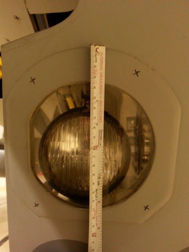
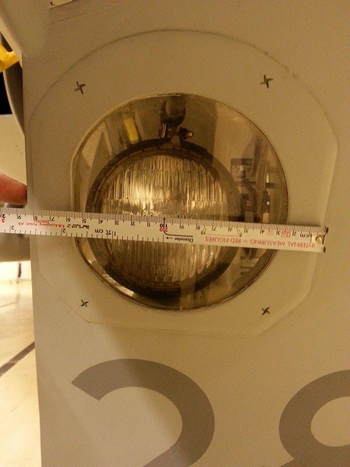
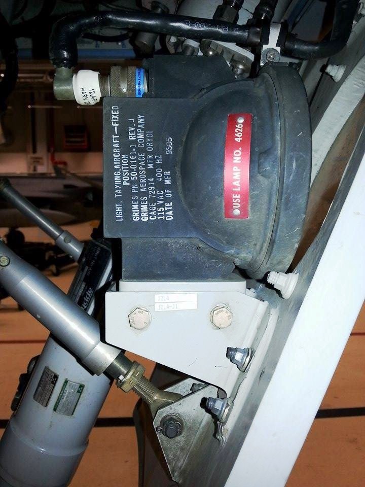
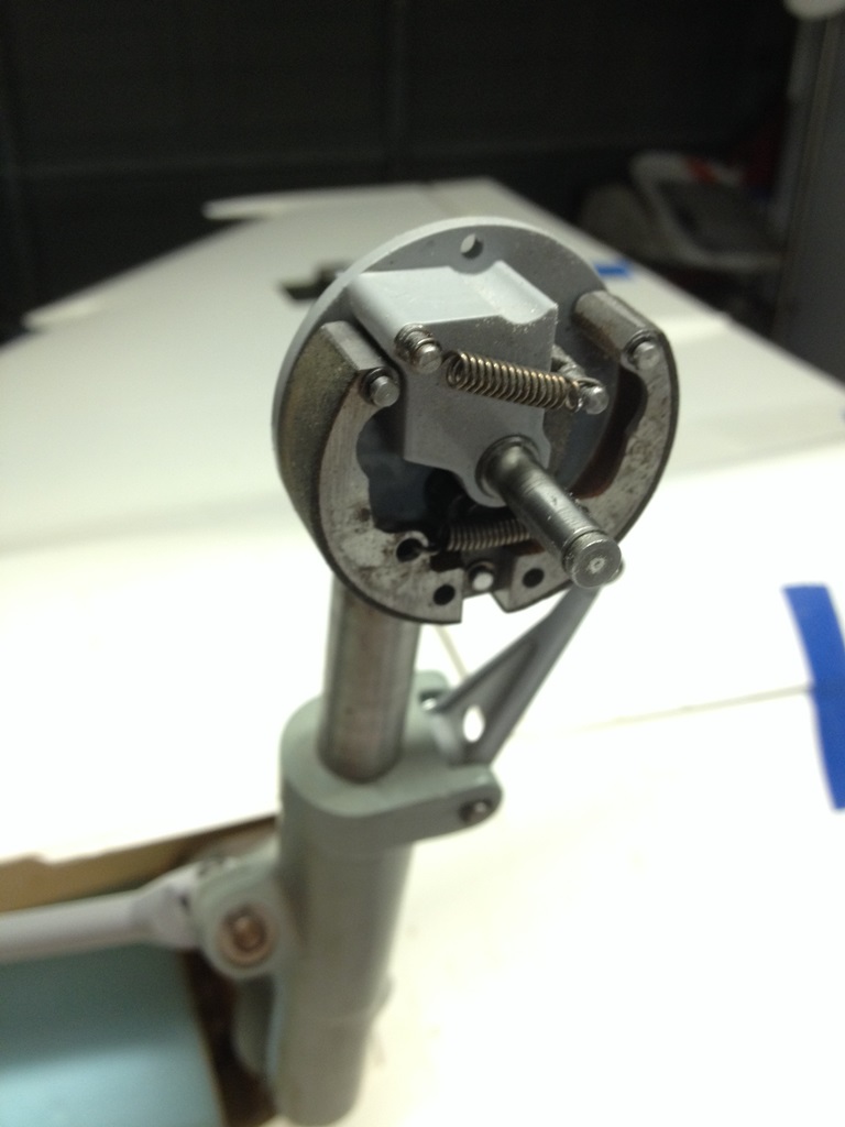
I'll be mounting the taxi light on the nose gear door this weekend. I needed some better pics so I sent my Gripen mechanic buddy in Sweden a message on Facebook. He went over to the hanger, and a couple of hours later I had the pics. The global information age is awesome, as are the pics.
Regards,
Jim
Regards,
Jim
03-02-2015, 07:31 AM
#1129
Hydraulic Landing Gear System - Continued
My initial setup of this system (see post #1117) resulted in gear retraction/extension times that were too slow. As such, I increased the size of the lines from 4mm to 6mm and replaced the ISO34 oil with less viscous ISO22 oil. The retraction & extension times are now much more realistic.
https://www.youtube.com/watch?v=a4A8O3iNqmg&feature=youtu.be Regards,
Jim
 03-02-2015, 10:51 AM
#1132
Fuel Tank & Main Gear Door Cylinders
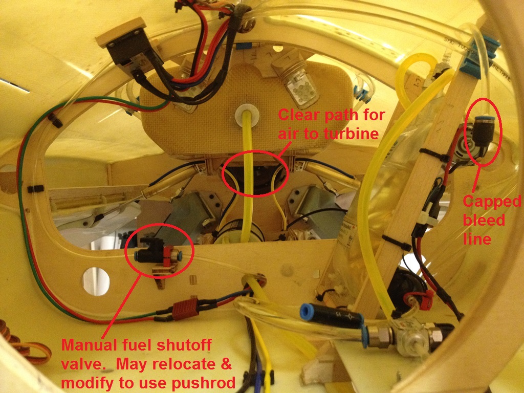
Further to Martin's warning about potentially blocking off the airflow to the turbine, I sent the fuel tank back to Gary at Jet Tech to be modified (made 1" shorter). Gary did a great job and I had the tank back in a week. Not only does it provide a clearer path for the airflow, but the bottom of the tank is the perfect hieght for mounting the door cylinders.


Regards,
Jim
Further to Martin's warning about potentially blocking off the airflow to the turbine, I sent the fuel tank back to Gary at Jet Tech to be modified (made 1" shorter). Gary did a great job and I had the tank back in a week. Not only does it provide a clearer path for the airflow, but the bottom of the tank is the perfect hieght for mounting the door cylinders.
Regards,
Jim
03-02-2015, 01:01 PM
#1133
Air System Installation
I had no choice but to use hydraulics on the landing gear because the design doesn't have mechanical up/down locks but relies on hydraulic lock (trapping the fluid in the cylinder) to lock the gear in position. However, the gear doors, speed brakes, and wheel brakes be operated via hydraulics or pneumatics. The gear doors and speed brakes use conventional BVM and Ultra Precision air cylinders. The wheel brakes are an Airworld design, but it is the same brake unit as is used on the MiG-21 and L-39 and I have personnally witnessed their successful operation using air.
I considered the pro's and con's of going with an air system as follows
Disadvantages of Using Air
1) limited supply of compressed air as opposed to hydraulic pump which will continue to provide fluid
2) additional components (fill valve, tanks) means more weight
3) I only had one extra hydraulic control valve - this would be handy to keep as a spare. I'd have to order at least three more from Austria.
4) High technical risk - the retract system needed to be replumbed due to the long retraction/extension times. Who knows what issues I might find with hydraulic doors and especially hydraulic brakes.
Advantages of Using Air
1) Low technical risk. We all have lots of experience with air systems and thus the probability of success (on the first try) is quite high.
2) Clean installation. The air lines are smaller and easier to route.
3) Ease of maintenance. It's air, not oil. I'd already taken one oil shower when I forgot to unplug the battery before disconnecting the pressure line.

Needless to say, after making this comparison, it was an easy decision to go with an air system. Although there would be the weight of the tanks and fill valve, these components probably weigh less than 4mm or 6mm oil-filled tubing.
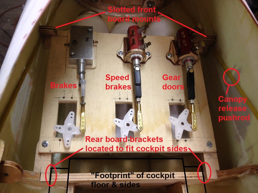
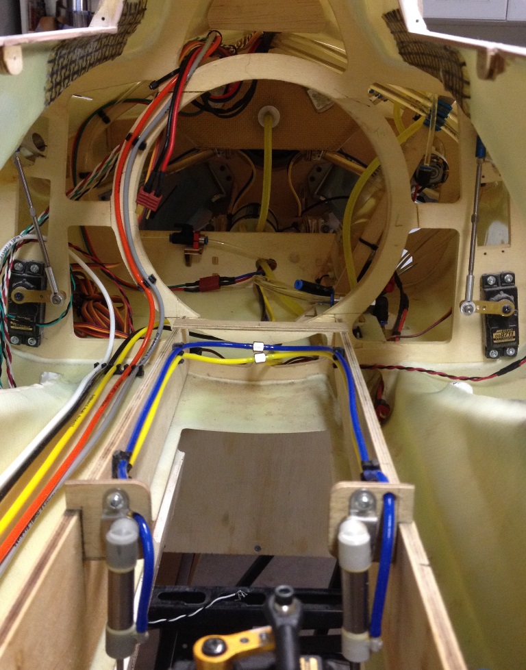
Other builders have put their receiver/power distribution systems in the nose and have installed the gear door, speed brake, and brake valves/servos in the mid-fuselage. I decided to swap those locations and install the air valves & servos in the nose and the Jeti CB200 and Bavarian Demon Cortex Gyro in the mid-fuselage. Access to the nose is much better (especially after I did the removeable nose cone bracket - see post #1032) so the installation & maintenance of the air components would be easier, and having the CB-200 in the mid-fuselage would shorten the servo wires to the flight controls (rather than having to run them all the way up into the nose).
The air component board is installed about 3/4" forward of the nose gear forward former. This gives room for the cockpit floor which overhangs the former. The rear brackets are mounted just outboard of the cockpit sides. In order to improve maintainability, the board is screwed to the rear brackets, but the board is captured at the front by slots in the front brackets. Therefore only two screws need to be removed to remove the board.
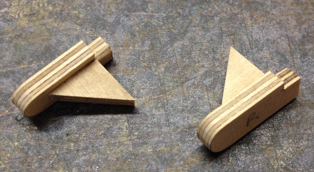
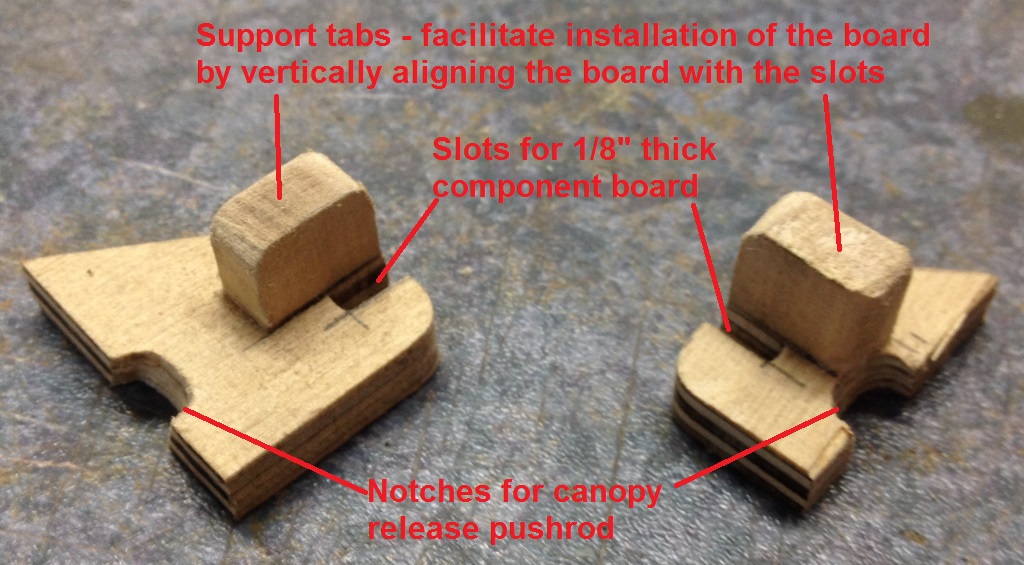
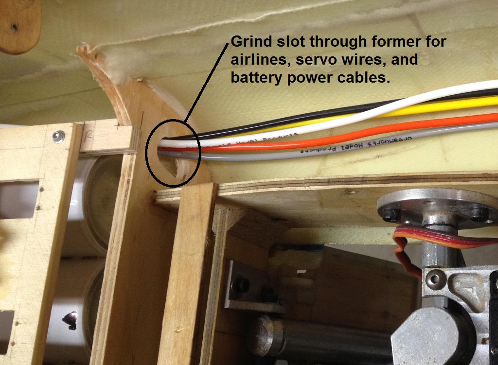
To facilitate the routing of the air tubing, i ground a slot theough the forward gear former on the right side; the hydraulic lines and fuel fill are routed along the left side.
Jim
I had no choice but to use hydraulics on the landing gear because the design doesn't have mechanical up/down locks but relies on hydraulic lock (trapping the fluid in the cylinder) to lock the gear in position. However, the gear doors, speed brakes, and wheel brakes be operated via hydraulics or pneumatics. The gear doors and speed brakes use conventional BVM and Ultra Precision air cylinders. The wheel brakes are an Airworld design, but it is the same brake unit as is used on the MiG-21 and L-39 and I have personnally witnessed their successful operation using air.
I considered the pro's and con's of going with an air system as follows
Disadvantages of Using Air
1) limited supply of compressed air as opposed to hydraulic pump which will continue to provide fluid
2) additional components (fill valve, tanks) means more weight
3) I only had one extra hydraulic control valve - this would be handy to keep as a spare. I'd have to order at least three more from Austria.
4) High technical risk - the retract system needed to be replumbed due to the long retraction/extension times. Who knows what issues I might find with hydraulic doors and especially hydraulic brakes.
Advantages of Using Air
1) Low technical risk. We all have lots of experience with air systems and thus the probability of success (on the first try) is quite high.
2) Clean installation. The air lines are smaller and easier to route.
3) Ease of maintenance. It's air, not oil. I'd already taken one oil shower when I forgot to unplug the battery before disconnecting the pressure line.
Needless to say, after making this comparison, it was an easy decision to go with an air system. Although there would be the weight of the tanks and fill valve, these components probably weigh less than 4mm or 6mm oil-filled tubing.
Other builders have put their receiver/power distribution systems in the nose and have installed the gear door, speed brake, and brake valves/servos in the mid-fuselage. I decided to swap those locations and install the air valves & servos in the nose and the Jeti CB200 and Bavarian Demon Cortex Gyro in the mid-fuselage. Access to the nose is much better (especially after I did the removeable nose cone bracket - see post #1032) so the installation & maintenance of the air components would be easier, and having the CB-200 in the mid-fuselage would shorten the servo wires to the flight controls (rather than having to run them all the way up into the nose).
The air component board is installed about 3/4" forward of the nose gear forward former. This gives room for the cockpit floor which overhangs the former. The rear brackets are mounted just outboard of the cockpit sides. In order to improve maintainability, the board is screwed to the rear brackets, but the board is captured at the front by slots in the front brackets. Therefore only two screws need to be removed to remove the board.
To facilitate the routing of the air tubing, i ground a slot theough the forward gear former on the right side; the hydraulic lines and fuel fill are routed along the left side.
Jim
Last edited by rcjets_63; 03-02-2015 at 03:14 PM.
03-03-2015, 06:15 AM
#1134
Hydraulic System - Completed
Here are some pics of the completed installation of the hydraulic power unit and control board.


Lighting System Installation
The Multi-Watt Pro lighting controller from Details 4 Scale was installed on the fuselage just behind the right inlet and directly over the navigation light. This location gives good access to the unit for programming/maintenance as well as to help counterbalance the weight of the hydraulic unit which was installed on the left side of the model. The light wires are bundled and tie-wrapped to the former to prevent them from potentially interfering with the canard operation. The wires for the taxi light on the nose landing gear and the landing lights on the main landing gear have been terminated at the controller and routed through the model then tied off as I haven't yet installed these lights on the landing gear. In the photos of the lights below, the tail strobe flashed as I took the picture of the left side of the plane. It is, of course, also visible from the right side too.


Cable Routing and ECU Installation
The photos below show the installation of the ECU immediately forward of the former at the front of the main landing gear bay. The ECU is installed the upper surface of the fuselage just to the right of the dorsal spine. From this location, a standard Kingtech Y-cable harness is just long enough to be routed through the dorsal spine to the turbine and to be routed around the former to reach the fuel pump. Two plastic tie-off pads were CA'd to the upper fuselage and the cables secured in place with tie wraps. The cable for the fuel pump and the servo wires for the throttle and Xicoy-Jeti turbine telemetry adapter were secured to the fuselage using Tidi-strips with extra slots for the right aileron and elevator servo wires. The Jeti CB200 power distribution unit and Bavarian Demon Cortex gyro will be installed to the right of centerline on the lower fuselage in the remaining space seen in the third photo below. Their installation is on the To-Do List for tonight.


Regards,
Jim
Here are some pics of the completed installation of the hydraulic power unit and control board.
Lighting System Installation
The Multi-Watt Pro lighting controller from Details 4 Scale was installed on the fuselage just behind the right inlet and directly over the navigation light. This location gives good access to the unit for programming/maintenance as well as to help counterbalance the weight of the hydraulic unit which was installed on the left side of the model. The light wires are bundled and tie-wrapped to the former to prevent them from potentially interfering with the canard operation. The wires for the taxi light on the nose landing gear and the landing lights on the main landing gear have been terminated at the controller and routed through the model then tied off as I haven't yet installed these lights on the landing gear. In the photos of the lights below, the tail strobe flashed as I took the picture of the left side of the plane. It is, of course, also visible from the right side too.
Cable Routing and ECU Installation
The photos below show the installation of the ECU immediately forward of the former at the front of the main landing gear bay. The ECU is installed the upper surface of the fuselage just to the right of the dorsal spine. From this location, a standard Kingtech Y-cable harness is just long enough to be routed through the dorsal spine to the turbine and to be routed around the former to reach the fuel pump. Two plastic tie-off pads were CA'd to the upper fuselage and the cables secured in place with tie wraps. The cable for the fuel pump and the servo wires for the throttle and Xicoy-Jeti turbine telemetry adapter were secured to the fuselage using Tidi-strips with extra slots for the right aileron and elevator servo wires. The Jeti CB200 power distribution unit and Bavarian Demon Cortex gyro will be installed to the right of centerline on the lower fuselage in the remaining space seen in the third photo below. Their installation is on the To-Do List for tonight.
Regards,
Jim
03-03-2015, 07:42 AM
#1138
Yes, winter is upon us. Just yesterday we had a winter storm in Phoenix. It got so cold that I needed to put on a jacket. We have a rule here that if the temperature in degrees Fahrenheit is less than your age in years, you stay home. A few degress more and I would have gotton the day off!
As for taking this bird on the road this summer, I'm afraid not. I get 15 days of vacation and my company allows us to buy up to 5 more days which gives me 20 days total. Top Gun will require 5 days, and the Jet World Masters will need 10 days. That leaves only 5 days left over for local jet events (BITW, Monster, Tucson, AZ Jet Rally) and I still need a couple of days after the JWM to go to Sweden to visit the Gripen base. As such, I've already told Tim and Lewis that unfortunately I will not be at Winamac or Kentucky this summer.
Regards,
Jim
03-04-2015, 10:36 AM
#1139
Landing Gear Door Operation, Failsafes, and Sequencers
The Gripen has what is typically known as “Mode 2” gear door functionality. This means that the doors are "normally" closed and only open to allow the gear to swing up or down. Here are some pics:
Aircraft is taking off in afterburner with doors closed. Doors open for gear retraction/extension (nose gear clamshell doors visible, main doors obscured in photo by pylon). Doors close.


To when the gear is extended for landing, the doors open and the gear is lowered, and the doors close. Here is a pic of the Gripen just after the main gear has touched down on landing and you can see the doors are closed. (An easy way of determining the plane is landing, not taking off, is that the speed brakes are open).

That seems pretty straightforward, but it doesn't explain these pics of the Gripen taxiing with the doors closed, and with the doors open. Nor does it explain the doors being open while the aircraft is parked.


So I called my Gripen mechanic friend to explain this to me. The door operation of the full scale Gripen is just a tad more complicated than Mode 2. When the plane is parked, the doors are open which provides easy access to the gear bays to assist the ground crew in maintaining the aircraft. The doors remain open until after the engine is started and the aircraft taxi speed exceeds 20 km/hr at which point they close. The doors then follow Mode 2 operation for the flight. Upon landing, the doors remain closed until the engine is shut down, at which point they open.
This functionality can be seen in the video:
https://m.youtube.com/watch?v=QJQKCUjcslM Here are some screen shots that point out the functionality:
Aircraft is taxiing.....0:34 doors are open, 0:35 doors are in mid-travel, 0:36 doors are closed.


Aircraft pulls into parking area....1:12 aircraft has just stopped and the doors are closed. 1:15 doors are still closed and the pilot shuts down engine, 1:20 the engine is off and the doors are open. 1:26 canopy half open as the pilot prepares to exit the cockpit.


A typical landing gear/door sequencer obviously will not replicate this functionality; they only give you the choice of Mode 1 (door open when gear down, doors closed when gear up), Mode 2, or Mode 3 (some doors open & some closed when gear down, all closed when gear is up). Choosing Mode 1 gives you the benefit of having the doors open which will help you service/maintain the model. However, when it is in the air with the gear down, or during the take off roll, it looks very very wrong.
Scale:
Not Scale:


Choosing Mode 2 looks good while the plane is taking off, flying, and taxiing, but the doors are closed when it is parked so it is harder to maintain the model. Normally, I would use a Mode 2 sequencer (along with an on-board failsafe) and simply locate the gear door servo to where it could be manually shifted if I needed to open the doors.
While the current generation of top end computer radios have built-in sequencers for retracts/gear door operation, most jet fliers don't use this functionality because we install failsafe systems (eg Tam's, Dreamworks) to automoatically lower the gear if the air pressure is leaks down. The on-board failsafe requires using an on-board sequencer.
However, the Jeti DC/DS-16 system doesn't have this limitation. With the new MBar sensor, the system pressure data is sent via telemetry back to to the transmitter. This is a breakthrough as it gives a failsafe AND allows the transmitter to control the gear doors. The transmitter can be programmed to lower the gear automatically, or to simply give you a warning of the problem and you can lower the gear yourself. The Gripen gear door functionality can be replicated by using the built-in sequencer and adding a mix through a two-position switch (where the mix is activate when the landing gear is down AND the two-position switch is in the desired positon). When the model is parked on the ground, the switch is put in the door open position. As the model is taxied for takeoff and the taxi speed exceeds 4 km/hr (walking speed), flip the switch to close the doors and the sequencer will take over from there. After flying and taxiing back to the pits, and then shutting down the engine, flip the switch again to open the doors. It might even be fun to experiement with the GPS telemetry and a logical switch to see if I can get the doors to automatically close when the taxi speed exceeds 4 km/hr. That would be da bomb!


Regards,
Jim.
The Gripen has what is typically known as “Mode 2” gear door functionality. This means that the doors are "normally" closed and only open to allow the gear to swing up or down. Here are some pics:
Aircraft is taking off in afterburner with doors closed. Doors open for gear retraction/extension (nose gear clamshell doors visible, main doors obscured in photo by pylon). Doors close.
To when the gear is extended for landing, the doors open and the gear is lowered, and the doors close. Here is a pic of the Gripen just after the main gear has touched down on landing and you can see the doors are closed. (An easy way of determining the plane is landing, not taking off, is that the speed brakes are open).
That seems pretty straightforward, but it doesn't explain these pics of the Gripen taxiing with the doors closed, and with the doors open. Nor does it explain the doors being open while the aircraft is parked.
So I called my Gripen mechanic friend to explain this to me. The door operation of the full scale Gripen is just a tad more complicated than Mode 2. When the plane is parked, the doors are open which provides easy access to the gear bays to assist the ground crew in maintaining the aircraft. The doors remain open until after the engine is started and the aircraft taxi speed exceeds 20 km/hr at which point they close. The doors then follow Mode 2 operation for the flight. Upon landing, the doors remain closed until the engine is shut down, at which point they open.
This functionality can be seen in the video:
https://m.youtube.com/watch?v=QJQKCUjcslM Here are some screen shots that point out the functionality:
Aircraft is taxiing.....0:34 doors are open, 0:35 doors are in mid-travel, 0:36 doors are closed.
Aircraft pulls into parking area....1:12 aircraft has just stopped and the doors are closed. 1:15 doors are still closed and the pilot shuts down engine, 1:20 the engine is off and the doors are open. 1:26 canopy half open as the pilot prepares to exit the cockpit.
A typical landing gear/door sequencer obviously will not replicate this functionality; they only give you the choice of Mode 1 (door open when gear down, doors closed when gear up), Mode 2, or Mode 3 (some doors open & some closed when gear down, all closed when gear is up). Choosing Mode 1 gives you the benefit of having the doors open which will help you service/maintain the model. However, when it is in the air with the gear down, or during the take off roll, it looks very very wrong.
Scale:
Not Scale:
Choosing Mode 2 looks good while the plane is taking off, flying, and taxiing, but the doors are closed when it is parked so it is harder to maintain the model. Normally, I would use a Mode 2 sequencer (along with an on-board failsafe) and simply locate the gear door servo to where it could be manually shifted if I needed to open the doors.
While the current generation of top end computer radios have built-in sequencers for retracts/gear door operation, most jet fliers don't use this functionality because we install failsafe systems (eg Tam's, Dreamworks) to automoatically lower the gear if the air pressure is leaks down. The on-board failsafe requires using an on-board sequencer.
However, the Jeti DC/DS-16 system doesn't have this limitation. With the new MBar sensor, the system pressure data is sent via telemetry back to to the transmitter. This is a breakthrough as it gives a failsafe AND allows the transmitter to control the gear doors. The transmitter can be programmed to lower the gear automatically, or to simply give you a warning of the problem and you can lower the gear yourself. The Gripen gear door functionality can be replicated by using the built-in sequencer and adding a mix through a two-position switch (where the mix is activate when the landing gear is down AND the two-position switch is in the desired positon). When the model is parked on the ground, the switch is put in the door open position. As the model is taxied for takeoff and the taxi speed exceeds 4 km/hr (walking speed), flip the switch to close the doors and the sequencer will take over from there. After flying and taxiing back to the pits, and then shutting down the engine, flip the switch again to open the doors. It might even be fun to experiement with the GPS telemetry and a logical switch to see if I can get the doors to automatically close when the taxi speed exceeds 4 km/hr. That would be da bomb!
Regards,
Jim.
Last edited by rcjets_63; 03-24-2015 at 05:24 PM.
 03-04-2015, 03:34 PM
#1141
Here's a bit of an update on the build as I've made some changes....
Initially I had installed the CAT UAT and the fuel pump between the longerons running between the main landing gear opening. I found that, due to a bit of play in the landing gear, it was possible for one of the tires to rub against the CAT. As such, I removed the fuel pump from this area which allowed the CAT to be reinstalled on the centerline such that it is well clear of the tires. The fuel pump was installed on the former at the front of the landing gear bay.
I think this layout improves the maintainability of the jet. There was just too much happening in one small area with the CAT and fuel pump installed together, particularly with all the fuel lines, pump wiring, air lines, and light wiring that needed to be routed between those longerons. The updated layout is shown below.


The air fill valve and fueling/defueling port as installated in the nose of the plane.

Regards,
Jim
P.S: Thomas, yes, the radio is quite incredible. I got my Jeti 18 months ago and, in my opinion, it was leaps and bounds ahead. Now, with the upgrades in the firmware, as well as the new suite of sensors, the Jeti radio provides an even greater level of capability.
Initially I had installed the CAT UAT and the fuel pump between the longerons running between the main landing gear opening. I found that, due to a bit of play in the landing gear, it was possible for one of the tires to rub against the CAT. As such, I removed the fuel pump from this area which allowed the CAT to be reinstalled on the centerline such that it is well clear of the tires. The fuel pump was installed on the former at the front of the landing gear bay.
I think this layout improves the maintainability of the jet. There was just too much happening in one small area with the CAT and fuel pump installed together, particularly with all the fuel lines, pump wiring, air lines, and light wiring that needed to be routed between those longerons. The updated layout is shown below.
The air fill valve and fueling/defueling port as installated in the nose of the plane.
Regards,
Jim
P.S: Thomas, yes, the radio is quite incredible. I got my Jeti 18 months ago and, in my opinion, it was leaps and bounds ahead. Now, with the upgrades in the firmware, as well as the new suite of sensors, the Jeti radio provides an even greater level of capability.
Last edited by rcjets_63; 03-04-2015 at 03:44 PM.
03-05-2015, 10:32 AM
#1142
Radio System & Gyro Installation
This model is being equipped with a Jeti Central Box 200 power distribution system with redundant R3 receivers and a full telemetry suite including a Jeti MBar air pressure system sensor, MSpeed pitot airspeed sensor, MUI-30 voltage/amperage/capacity sensor, EX 4 expander, and a Xicoy ECU sensor. Additionally, a Bavarian Demon Cortex gyro is being installed on the elevator, aileron, and rudder channels (canards not on gyro). Many thanks to http://www.DemonAero.com and Captron (makers of Bavarian Demon gyros) for their sponsorship of Jet Team USA! Additionally, a GWS PG-03 gyro (non-remote gain) is being fitted to the nose wheel steering.
The CB200 and Cortex are installed on a 2-1/2" x 4-1/2" platform fitted to the rear side of the canard bearing former to the right of center. If I had to do it again, I'd install the platform about 1/2" further outboard than shown in the pictures to give a bit more room to connect the wiring on the left side of the CB and keep the wiring out of the airflow. I zip tied the wiring loom between the CB200 and Cortex so that the wires support each other and cannot move around. The platform is screwed to wooden mounting rails as this makes it easy to install the connectors. The platform is elevated so that servo & telemetry wiring can be routed underneath, as required, for a cleaner installation.


There are six servo cables which run forward to the nose of the model. These are: switch, nose wheel steering, brakes, air brakes, gear doors, and the Ext line for the MBar sensor in the nose (into which the MSpeed sensor is daisy chained). The cables from the retract servo and the left canard are routed through the cutouts below the inlet circle in the canard former and through a hole made through the left longeron. The Ext cable from the nose is also routed through this hole, through the canard former, and rearwards towards the CB200. The cables routing and other tips are shown in the photos below. I left sufficient slack in the air lines & cables so that the entire front component board can be unscrewed and pulled rearwards into the cockpit opening area for maintenance, if required.


As you can see in the photos, I haven't yet routed the servo lines to the Cortex, and all the telemetry/servo connections at the right side of the CB200. I'll added some photos of that routing when I have it finalized.
Regards,
Jim
This model is being equipped with a Jeti Central Box 200 power distribution system with redundant R3 receivers and a full telemetry suite including a Jeti MBar air pressure system sensor, MSpeed pitot airspeed sensor, MUI-30 voltage/amperage/capacity sensor, EX 4 expander, and a Xicoy ECU sensor. Additionally, a Bavarian Demon Cortex gyro is being installed on the elevator, aileron, and rudder channels (canards not on gyro). Many thanks to http://www.DemonAero.com and Captron (makers of Bavarian Demon gyros) for their sponsorship of Jet Team USA! Additionally, a GWS PG-03 gyro (non-remote gain) is being fitted to the nose wheel steering.
The CB200 and Cortex are installed on a 2-1/2" x 4-1/2" platform fitted to the rear side of the canard bearing former to the right of center. If I had to do it again, I'd install the platform about 1/2" further outboard than shown in the pictures to give a bit more room to connect the wiring on the left side of the CB and keep the wiring out of the airflow. I zip tied the wiring loom between the CB200 and Cortex so that the wires support each other and cannot move around. The platform is screwed to wooden mounting rails as this makes it easy to install the connectors. The platform is elevated so that servo & telemetry wiring can be routed underneath, as required, for a cleaner installation.
There are six servo cables which run forward to the nose of the model. These are: switch, nose wheel steering, brakes, air brakes, gear doors, and the Ext line for the MBar sensor in the nose (into which the MSpeed sensor is daisy chained). The cables from the retract servo and the left canard are routed through the cutouts below the inlet circle in the canard former and through a hole made through the left longeron. The Ext cable from the nose is also routed through this hole, through the canard former, and rearwards towards the CB200. The cables routing and other tips are shown in the photos below. I left sufficient slack in the air lines & cables so that the entire front component board can be unscrewed and pulled rearwards into the cockpit opening area for maintenance, if required.
As you can see in the photos, I haven't yet routed the servo lines to the Cortex, and all the telemetry/servo connections at the right side of the CB200. I'll added some photos of that routing when I have it finalized.
Regards,
Jim
Last edited by rcjets_63; 03-05-2015 at 10:47 AM.
 03-05-2015, 03:25 PM
#1144

My Feedback: (5)
Join Date: Dec 2011
Location: Holland Patent,
NY
Posts: 717
Likes: 0
Received 0 Likes
on
0 Posts
Hi Jim,
Question- why aren't you stabilizing the canards via Cortex? I recently purchased a Cortex with the intent of stabilizing the canards as well as the elevons and rudder. On my SM/Extreme Gripen, I am currently using a JR rate gyro for nose wheel steering and intend to keep it as such unless recommended otherwise.
Many thanks for posting your Gripen build on RCU with some GREAT info being presented. I'm closely following every post.
Rgds,
Art ARRO in the frozen tundra of CNY- 54 continuous days of sub-freezing weather.
03-05-2015, 04:12 PM
#1145
Hi Art,
Sorry to hear about your weather. 54 days of freezing weather. Wow, 76 and sunny in Phoenix as I type this.
If this was a SM/Extreme Gripen, I'd put the Cortex on the canards (both driven by a single servo), elevons, rudder, and nose wheel steering which gives a total of five servos. However, the Airworld Gripen has separate elevators (2) and ailerons (2), rudder, and separate canards (2). Add nose wheel steering and that totals 8 servos that could potentially use a gyro. The Cortex (and iGyro for that matter) have only 5 input/outputs. I don't want to use Y-cables or Matchboxes so choices had to be made as to what gets eliminated.
I've had a lot of luck with the GWS PG-03 on nose wheel steering on several jets. Turn the pot to the 11 o'clock position, install it, and forget it. The PG-03 is a great inexpensive little gyro and remote gain hasn't been required (in my experience) and thus eliminates a gain channel. It is less expensive that a typical remote gain JR gyro.
The Cortex is, of course, da bomb and I've been very happy with its performance in other jets. I've heard through the grapevine that Captron (makers of Bavarian Demon gyros) is looking at making a 6, 7, or 8 input/output unit but I don't know when it will be available. Also, I'm working with a hardware/software developer to make a custom microprocessor unit to control the canards and provide functionality similar to the full scale for takeoff, landing, and high AOA flight.
Regards,
Jim
03-09-2015, 09:09 PM
#1147
Switch Installation
Rather than installing the magnetic switch that comes with the Central Box, I decided to install a regular mechanical switch. It’s not that there is anything wrong with the magnetic switch, I’m just afraid of having a “blonde moment” and losing the magnet somewhere.
The functionality of the magnetic switch is that, when in the “off” position, it connects the outer two pins of the 3 conductor servo wire. In the “on” position there is no connection. This is why it is referred to as a “failsafe” switch. In order to turn the plane off, the switch must be functioning.
As an alternative, I use a Spektrum SPM6820 Soft Switch which is used with JR and Spektrum PowerSafe receivers. It’s a physically small switch which makes it easy to install almost anywhere. In my case, I installed it on a little panel glued to the front former. Removing the nose cone gives access to the fueling port, air system fill port, and the switch.
Regards,
Jim
03-09-2015, 09:11 PM
#1148
Vent Port
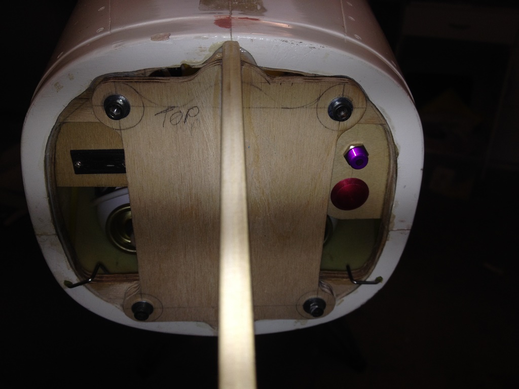
I wanted to maintain the scale fidelity of the plane as much as possible and the vent line presented a bit of a problem. Installing an external nipple style vent fitting was out of the question because there is no such similar feature on the bottom of the full scale Gripen. The fuel dump valve, located near the trailing edge of the fixed portion of the right wing, suggested a recessed or flush mount style vent connection (eg Dreamworks Fuselage Flush Mount Vent or GBR-Jets Maglok Vent). However, the dump valve is in the wing root which isn’t tall enough to allow for the installation of either of these straight vent fittings. A 90 degree fitting is required.
My solution was to purchase a 90 degree brass barbed fitting from Jet Tech. This is the same fitting that is Hysol’d to the top of the fuel tank. For the fuselage vent, I simply filed off the threads on the fitting, and Hysol’d it to a couple of .060 thick G-10 discs. The outer disc is cut to the scale outer diameter of the dump valve, and the inner (larger) disc provides larger surface for gluing the assembly to the inside of the fuselage.


To connect the taxi tank, I found that BVM fuel tank tubing placed over a barb fitting can be pressed into the orifice and forms a tight seal. The other end of the tubing is connected to the taxi tank.
Regards,
Jim
I wanted to maintain the scale fidelity of the plane as much as possible and the vent line presented a bit of a problem. Installing an external nipple style vent fitting was out of the question because there is no such similar feature on the bottom of the full scale Gripen. The fuel dump valve, located near the trailing edge of the fixed portion of the right wing, suggested a recessed or flush mount style vent connection (eg Dreamworks Fuselage Flush Mount Vent or GBR-Jets Maglok Vent). However, the dump valve is in the wing root which isn’t tall enough to allow for the installation of either of these straight vent fittings. A 90 degree fitting is required.
My solution was to purchase a 90 degree brass barbed fitting from Jet Tech. This is the same fitting that is Hysol’d to the top of the fuel tank. For the fuselage vent, I simply filed off the threads on the fitting, and Hysol’d it to a couple of .060 thick G-10 discs. The outer disc is cut to the scale outer diameter of the dump valve, and the inner (larger) disc provides larger surface for gluing the assembly to the inside of the fuselage.
To connect the taxi tank, I found that BVM fuel tank tubing placed over a barb fitting can be pressed into the orifice and forms a tight seal. The other end of the tubing is connected to the taxi tank.
Regards,
Jim
03-09-2015, 09:13 PM
#1149
Weight and Balance
Now that most of the equipment was installed in the plane, I performed an initial balancing of the model to determine where the batteries would have to be installed for the jet to balance. This resulted in a bit of a surprise. I’d fully expected to have to install all of the batteries on the wooden profile former underneath the nose cone. As it turns out, the batteries needed to be installed much, much closer to the C.G. The K210 turbine is almost two pounds lighter than a P200SX, and thus less nose weight is needed to counterbalance the turbine.
I set up a sling system and suspended the model with the sling located a 220 mm from the front of the wing tube as per Airworld instructions. Janne (jseppanen) stated in the Airworld Gripen thread that he balanced his plane at230mm in front of the tube but thinks that 220 might be better. I’m hoping that having the C.G. further aft will help reduce the Gripen take-off hop.
For the initial balance, the UAT was empty (hadn’t yet put fuel in the plane) and I’d put 200 grams of lead on the cockpit seat (to simulate the weight of my YT International 1/5[SUP]th[/SUP] scale “Euro” jet pilot). The plane balanced with a Kingtech 3800mah battery behind the C.G. where I was planning on installing it between the main landing gear. The two Rx batteries were pretty much at the canard pivot point as this would always access for charging by removing the inlets. At this point, the plane was essentially balanced, so any additional battery (or batteries) for the lights and HPU unit were placed on the C.G. (light blue 3800 mah Glacier LiPo is shown in the photo).
The all up weight of the plane at this point was 41.0 lbs which is comfortably below the Jet World Master’s limit of 44 lbs (20 Kg) dry and gives 3.0 lbs of room for paint and scale details.


Regards,
Jim
Now that most of the equipment was installed in the plane, I performed an initial balancing of the model to determine where the batteries would have to be installed for the jet to balance. This resulted in a bit of a surprise. I’d fully expected to have to install all of the batteries on the wooden profile former underneath the nose cone. As it turns out, the batteries needed to be installed much, much closer to the C.G. The K210 turbine is almost two pounds lighter than a P200SX, and thus less nose weight is needed to counterbalance the turbine.
I set up a sling system and suspended the model with the sling located a 220 mm from the front of the wing tube as per Airworld instructions. Janne (jseppanen) stated in the Airworld Gripen thread that he balanced his plane at230mm in front of the tube but thinks that 220 might be better. I’m hoping that having the C.G. further aft will help reduce the Gripen take-off hop.
For the initial balance, the UAT was empty (hadn’t yet put fuel in the plane) and I’d put 200 grams of lead on the cockpit seat (to simulate the weight of my YT International 1/5[SUP]th[/SUP] scale “Euro” jet pilot). The plane balanced with a Kingtech 3800mah battery behind the C.G. where I was planning on installing it between the main landing gear. The two Rx batteries were pretty much at the canard pivot point as this would always access for charging by removing the inlets. At this point, the plane was essentially balanced, so any additional battery (or batteries) for the lights and HPU unit were placed on the C.G. (light blue 3800 mah Glacier LiPo is shown in the photo).
The all up weight of the plane at this point was 41.0 lbs which is comfortably below the Jet World Master’s limit of 44 lbs (20 Kg) dry and gives 3.0 lbs of room for paint and scale details.
Regards,
Jim
03-09-2015, 09:28 PM
#1150
Battery Selection & Installation
Based on the outcome of the initial weight and balance, as well as some expert advice from fellow SVF club member and Team Horizon pilot Tony Quist, I made a few changes to the battery selection.
Rather than using a 3800mah 3S LiFe Kingtech battery, Tony suggested a 2100mah 3S LiFe as he’s using one with his K-210 powered Hawk and it good for five flights.
I’d purchased two Electrodynamics Nano 2600mah A123 batteries for Rx power via the Central Box 200. A123’s have the advantage of not requiring a regulator, but they are a bit on the heavy side. Tony suggested Spektrum 2S 3000mah LiFe batteries (P/N SPMB3000LFRX) which will weigh a bit less than the A123’s, also will not require a regulator, and are a compact size and near-square shape for easy installation. Unfortunately, they are on back-order at Horizon. As such, I decided to install the A123’s but will order a set of the LiFe batteries for later use on this (or another jet).

I’m not sure how much capacity (mah) the hydraulic pump motor will take (though I don’t suspect it will be very much per flight). The light system is also a bit of an unknown. The hydraulics are a “flight critical” system (always good to be able to get the landing gear down) but the lights are for looks only and it really doesn’t matter very much if they suck down a battery. As such, I decide to install separate packs for each system. I had a Fromeco 5200 mah Relion 2S2P pack on hand so I opened up the pack and used the cells to make two 2S1P packs.
The batteries were installed as follows:

ECU battery: The stock connector was cut off the battery and 16 gauge wires and a ribbed “Deans” style connector was soldered in place to make a lead that was about 12” long. The battery was Velco'd to the inside face of the right longeron. The leads were run through the hole I’d previously made at the centerline of the former at the front of the main gear bay. The lead from the ECU was re-routed (from going forward from the ECU along the dorsal) to run alongside the ECU-pump wiring running around the right side of the jet.


Receiver batteries: The A123 packs came with 12” leads and a Dean’s connector. The Dean’s was cut off and replaced with a Multiplex connector to mate with the CB200. The batteries were installed immediately aft of the canard former to a small Lite ply bracket CA’d to the fuselage side. The stock lead was more than long enough to reach the CB200 for the battery installed on the right side, but about 10” extension was needed for the left-mounted battery. The charge leads were routed forward through the former to Tidi-strips installed at the opening for the removable air intakes.


Hydraulic Pump and Light Batteries: These batteries were Velcro’d & tie-wrapped on the outboard side of the nose longerons immediately in front of the canard former. The Dean connectors removed from the A123 packs were fitted to these packs. The mounting location provides easy access for disconnecting or charging via the removable air intake. I had to slightly relocate the nose servo wires away from the right longeron to enough room to place the light system battery.


I’m expecting this configuration to come in a bit nose heavy because a lighter ECU battery was installed behind the C.G. and the hydraulics and light batteries were installed farther forward than during the initial balance. As such, a bit of tail weight will likely be required to balance the jet in its unpainted condition. Since there is more surface area behind the C.G. than in front, painting the jet will essentially add more weight to the rear and the lead will be removed.
Regards,
Jim
Based on the outcome of the initial weight and balance, as well as some expert advice from fellow SVF club member and Team Horizon pilot Tony Quist, I made a few changes to the battery selection.
Rather than using a 3800mah 3S LiFe Kingtech battery, Tony suggested a 2100mah 3S LiFe as he’s using one with his K-210 powered Hawk and it good for five flights.
I’d purchased two Electrodynamics Nano 2600mah A123 batteries for Rx power via the Central Box 200. A123’s have the advantage of not requiring a regulator, but they are a bit on the heavy side. Tony suggested Spektrum 2S 3000mah LiFe batteries (P/N SPMB3000LFRX) which will weigh a bit less than the A123’s, also will not require a regulator, and are a compact size and near-square shape for easy installation. Unfortunately, they are on back-order at Horizon. As such, I decided to install the A123’s but will order a set of the LiFe batteries for later use on this (or another jet).
I’m not sure how much capacity (mah) the hydraulic pump motor will take (though I don’t suspect it will be very much per flight). The light system is also a bit of an unknown. The hydraulics are a “flight critical” system (always good to be able to get the landing gear down) but the lights are for looks only and it really doesn’t matter very much if they suck down a battery. As such, I decide to install separate packs for each system. I had a Fromeco 5200 mah Relion 2S2P pack on hand so I opened up the pack and used the cells to make two 2S1P packs.
The batteries were installed as follows:
ECU battery: The stock connector was cut off the battery and 16 gauge wires and a ribbed “Deans” style connector was soldered in place to make a lead that was about 12” long. The battery was Velco'd to the inside face of the right longeron. The leads were run through the hole I’d previously made at the centerline of the former at the front of the main gear bay. The lead from the ECU was re-routed (from going forward from the ECU along the dorsal) to run alongside the ECU-pump wiring running around the right side of the jet.
Receiver batteries: The A123 packs came with 12” leads and a Dean’s connector. The Dean’s was cut off and replaced with a Multiplex connector to mate with the CB200. The batteries were installed immediately aft of the canard former to a small Lite ply bracket CA’d to the fuselage side. The stock lead was more than long enough to reach the CB200 for the battery installed on the right side, but about 10” extension was needed for the left-mounted battery. The charge leads were routed forward through the former to Tidi-strips installed at the opening for the removable air intakes.
Hydraulic Pump and Light Batteries: These batteries were Velcro’d & tie-wrapped on the outboard side of the nose longerons immediately in front of the canard former. The Dean connectors removed from the A123 packs were fitted to these packs. The mounting location provides easy access for disconnecting or charging via the removable air intake. I had to slightly relocate the nose servo wires away from the right longeron to enough room to place the light system battery.
I’m expecting this configuration to come in a bit nose heavy because a lighter ECU battery was installed behind the C.G. and the hydraulics and light batteries were installed farther forward than during the initial balance. As such, a bit of tail weight will likely be required to balance the jet in its unpainted condition. Since there is more surface area behind the C.G. than in front, painting the jet will essentially add more weight to the rear and the lead will be removed.
Regards,
Jim
Last edited by rcjets_63; 03-09-2015 at 09:44 PM.