


Composite ARF Mig29

 12-27-2018, 09:50 PM
#502

Well, I’m on board. I’m restoring one of these, no clue how long ago it was built but long enough to have some shoddy repairs and lots of brittle epoxy and CA joints. But it appears it at least has flown. Should be fun.
Couple of starting out points.
1. Has anyone actually had any success with a pneumatic setup for the retracts? All I see mentioned here is hydraulic, but this one is set up for air for now. I’ll likely at least try to stick with it.
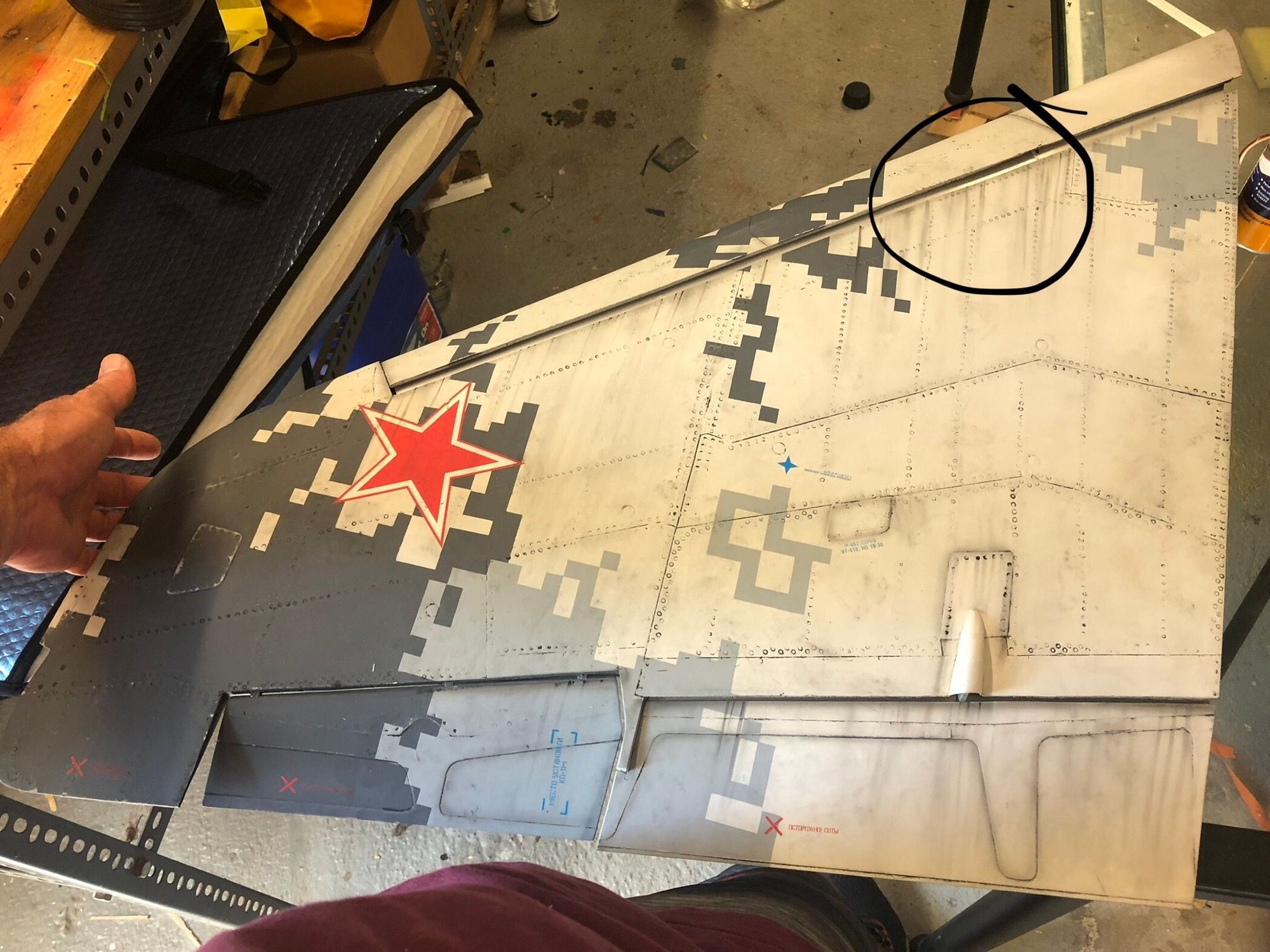
2. Did anyone else reinforce the bottom fuselage skin? This airframe is so flimsy it gives way and creaks/crackles even when lifting it empty - I’m planning to add some CF cloth in a few critical spots to aid with lifting and transport and also add some strength in the event of a gear up landing, just curious if any others had done the same.
3. Am I correct in assuming the fuel tanks are essentially built into the airplane? The upper rear tank appears to even be captured by the wing spar tube. So far I’ve been able to remove one of the tank stoppers to find some stiff as a board tygon clunk line, will be doing the same on the other tank. It sure would be easier if I could get them out, but that’s not happening.
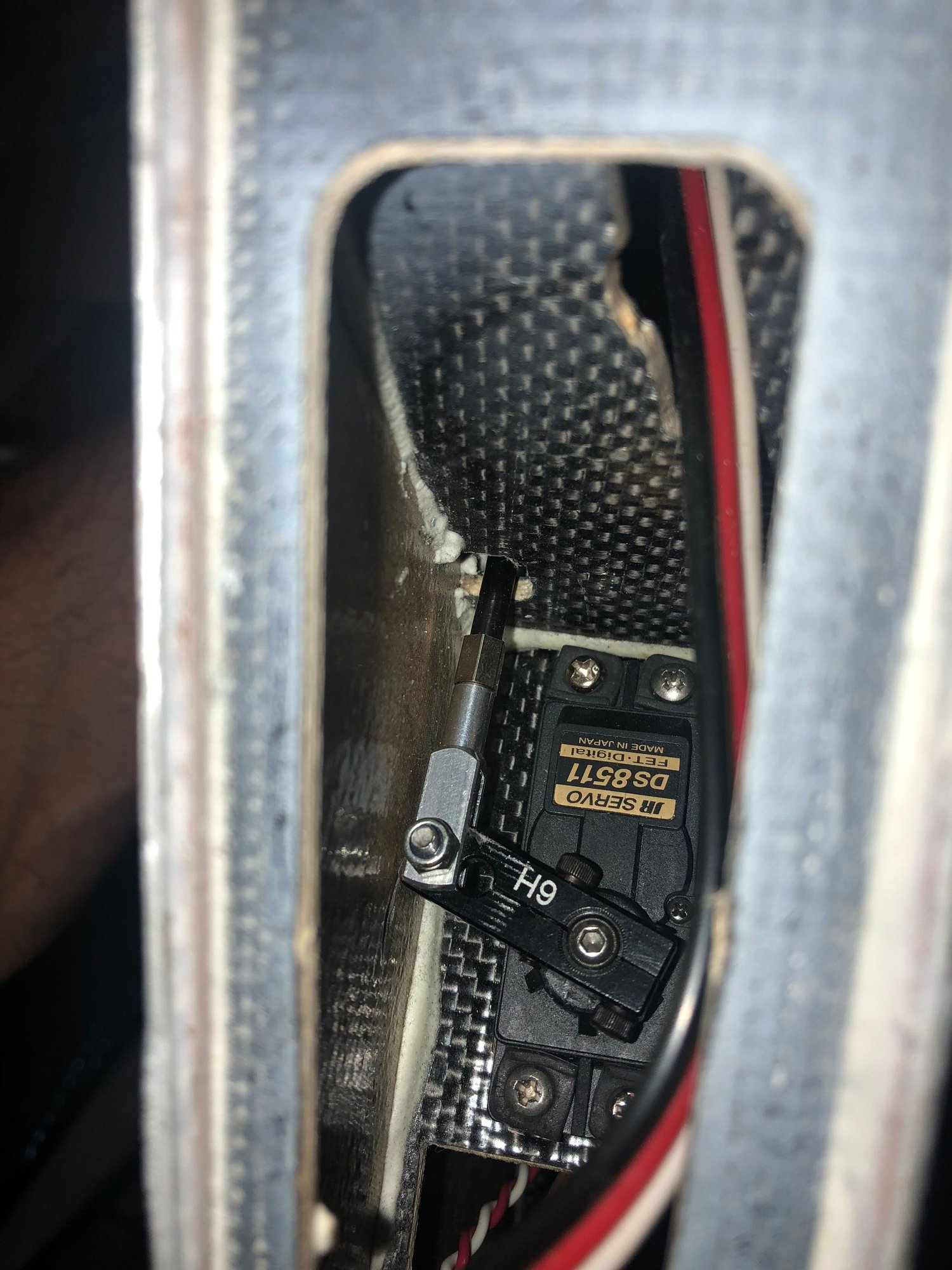
4. Anyone flying with the leading edge slats? This model has them screwed shut, may try to open them up eventually. Haven’t found any pictures of servo and linkage setup for the slats.
Couple of starting out points.
1. Has anyone actually had any success with a pneumatic setup for the retracts? All I see mentioned here is hydraulic, but this one is set up for air for now. I’ll likely at least try to stick with it.
2. Did anyone else reinforce the bottom fuselage skin? This airframe is so flimsy it gives way and creaks/crackles even when lifting it empty - I’m planning to add some CF cloth in a few critical spots to aid with lifting and transport and also add some strength in the event of a gear up landing, just curious if any others had done the same.
3. Am I correct in assuming the fuel tanks are essentially built into the airplane? The upper rear tank appears to even be captured by the wing spar tube. So far I’ve been able to remove one of the tank stoppers to find some stiff as a board tygon clunk line, will be doing the same on the other tank. It sure would be easier if I could get them out, but that’s not happening.
4. Anyone flying with the leading edge slats? This model has them screwed shut, may try to open them up eventually. Haven’t found any pictures of servo and linkage setup for the slats.
Last edited by Auburn02; 12-27-2018 at 10:13 PM.
12-28-2018, 05:49 AM
#503

Join Date: May 2002
Location: Washington,
MI
Posts: 221
Likes: 0
Received 0 Likes
on
0 Posts
the only air operated retract system was made Matrix Machine. You can tell easy enough because the air cylinder and operating mechanism is located on the inside of the turbine housing. That system works pretty well and provides solid up and down locks. If it�s not that system and just air to the original cylinders you won�t have any locks
12-28-2018, 05:50 AM
#504

Hi Auburn,
I reinforced the entire length of my inlets with carbon fibre as the fuse was very weak in that area. The reason the hydraulics are required on the gear is to achieve hydraulic lock on the gear. There is no mechanical lock on the gear. The fuel tanks are essentially built in, at least the front one on the original kits was. Levi and others are flying with the slats active without issues.
Mine has not flown yet but is almost done. Levi and David will give you their input I am sure.
12-28-2018, 07:20 AM
#505
Thanks guys. These would be the Matrix gear then, they have conventional locks...and the air cylinders in the turbine bays is a dead giveaway too.
My plan is to reinforce the bottom of the inlets and the lower nose area around and just forward of the nose gear. Shouldn�t add much weight.
Sounds like the fuel tank maintenance will just be an exercise in dexterity!
My plan is to reinforce the bottom of the inlets and the lower nose area around and just forward of the nose gear. Shouldn�t add much weight.
Sounds like the fuel tank maintenance will just be an exercise in dexterity!
12-28-2018, 10:20 AM
#506
My Feedback: (44)

Join Date: Sep 2004
Location: Wilmette,
IL
Posts: 439
Likes: 0
Received 0 Likes
on
0 Posts
HI guys,
I just finished mine with the extra cylinder by the nose gear, I received back two weeks ago.
Now I will wait for the weather, I will keep you updated.
Nick
I just finished mine with the extra cylinder by the nose gear, I received back two weeks ago.
Now I will wait for the weather, I will keep you updated.
Nick
12-28-2018, 12:20 PM
#508
 12-30-2018, 02:40 AM
#514
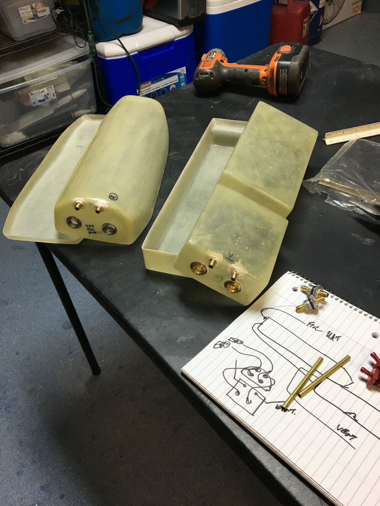
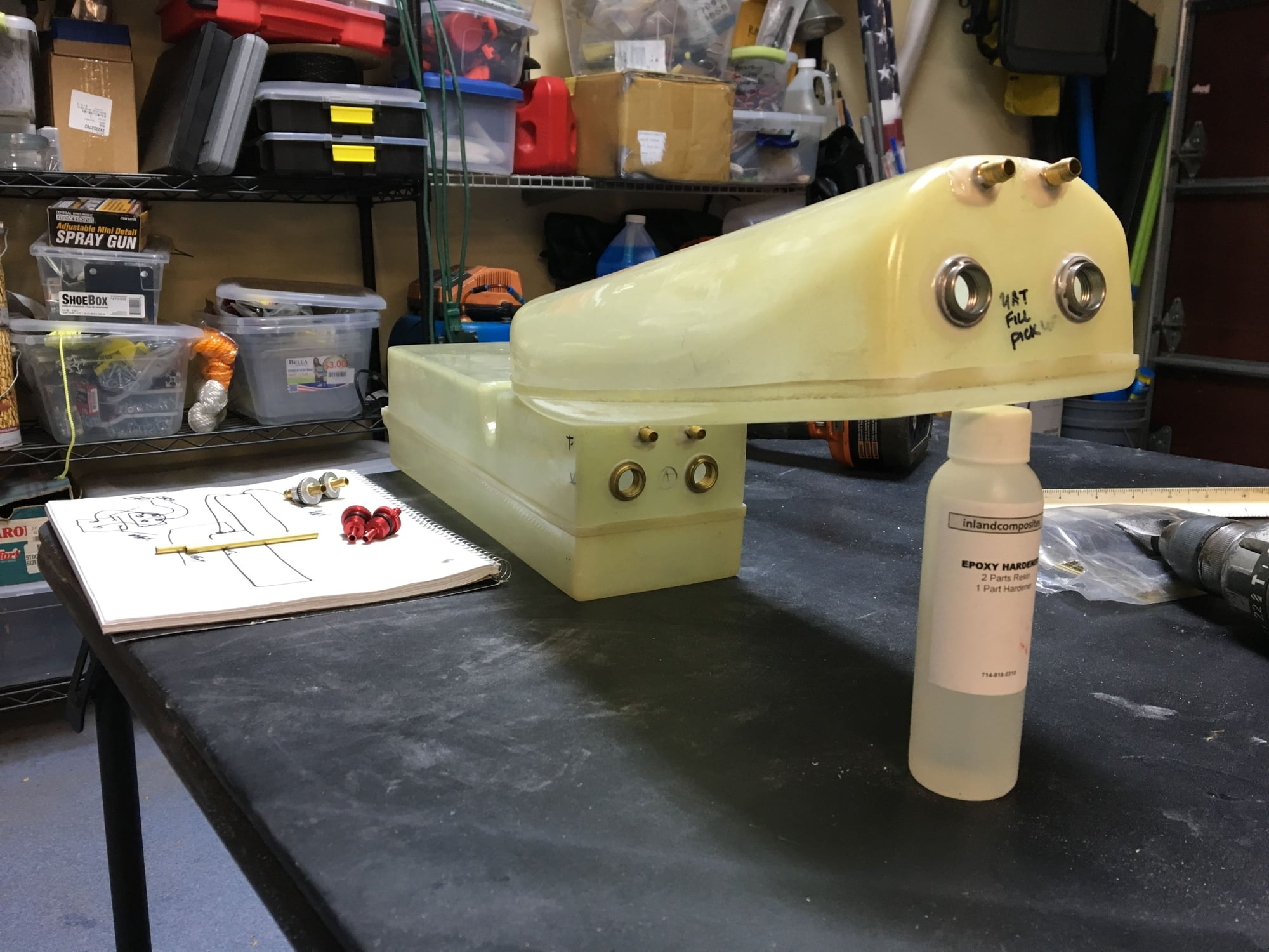
I have the two rear tanks for one turbine and the front centre tank for the other. That way I’m keeping both fuel systems seperate for redundancy. Both systems have almost identical capacity
12-30-2018, 07:55 AM
#516
Ah, I do recall reading there was more than one tank setup for this airplane. This one just has two tanks, one between the nacelles and one up in the turtle deck behind the cockpit. Hard to tell with them both stuck in the plane how close the capacity is between them. I�m leaning towards draining the rear tank first and installing two clunks in the front tank to go to the separate UATs.
 12-30-2018, 06:05 PM
#518
That setup looks ideal. I�d love to be able to install clunk and vent fittings like those, but with these tanks already inside I�m limited to the standard stopper style. I will at least punch two feed lines with twin clunks into the forward tank instead of the tee fitting off of a single clunk like is there now. I just hope the single vent line will be sufficient to keep up with the two engines drawing fuel from it.
12-30-2018, 07:54 PM
#519
My Feedback: (44)
Join Date: Sep 2004
Location: Wilmette,
IL
Posts: 439
Likes: 0
Received 0 Likes
on
0 Posts
Hi there I will not recommend a single vent line with two engines sucking, you will definitely have an issue of the engines stalling try to do something to incorporate two vent lines .
12-31-2018, 09:21 AM
#520
I think I am inclined to agree with you there after thinking about it a bit. The good new is I can get to the top edge of the tank with a drillbit and hysol in some vent fittings like you've done - the problem is with the tanks stuck in the airplane, trying to flush and clean them out is going to be a nightmare. But this will work - I'll run two clunks into each tank off the stopper lines, and drill two vents into each tank like you have done in your pictures.
Did you happen to measure the capacities of each tank by chance? My only other thought is if the two tanks were close in size, I could simply dedicate a tank per engine and run them as separate systems. But from the looks of it the rear tank is a good bit larger.
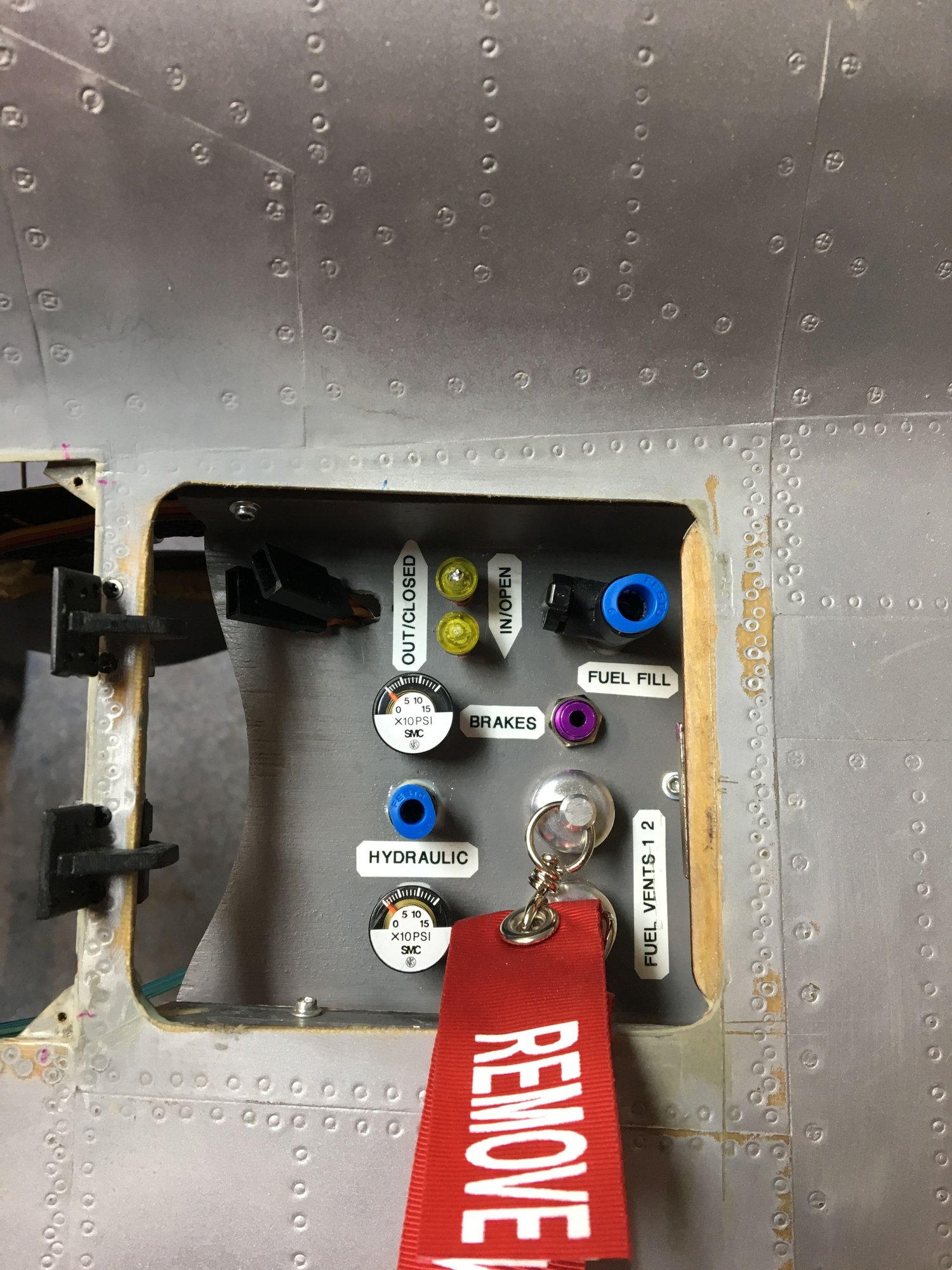
Next question for the group, where have you guys set up your service access for air fills, fuel fills, and fuel shutoff? There are some panels just behind the upper intake vents that seem like they would make a good place for it, but don't want to reinvent the wheel if there are better ideas. On the CARF SU-27 I built I did everything inside the nose cone, but this one is going to be a lot tighter up there especially if the batteries need to be there like I suspect they will.
Did you happen to measure the capacities of each tank by chance? My only other thought is if the two tanks were close in size, I could simply dedicate a tank per engine and run them as separate systems. But from the looks of it the rear tank is a good bit larger.
Next question for the group, where have you guys set up your service access for air fills, fuel fills, and fuel shutoff? There are some panels just behind the upper intake vents that seem like they would make a good place for it, but don't want to reinvent the wheel if there are better ideas. On the CARF SU-27 I built I did everything inside the nose cone, but this one is going to be a lot tighter up there especially if the batteries need to be there like I suspect they will.
12-31-2018, 11:21 AM
#521
My Feedback: (44)
Join Date: Sep 2004
Location: Wilmette,
IL
Posts: 439
Likes: 0
Received 0 Likes
on
0 Posts
Hi there first for the drilling while you drill use a vacuum cleaner very close with a stick right at the drilling area then use compressed air while having the pick up fuel hole open . for the capacity of the tanks I have not measured them but I think this should be around 200 oz. for the fill up position let me see if I can get a picture for you 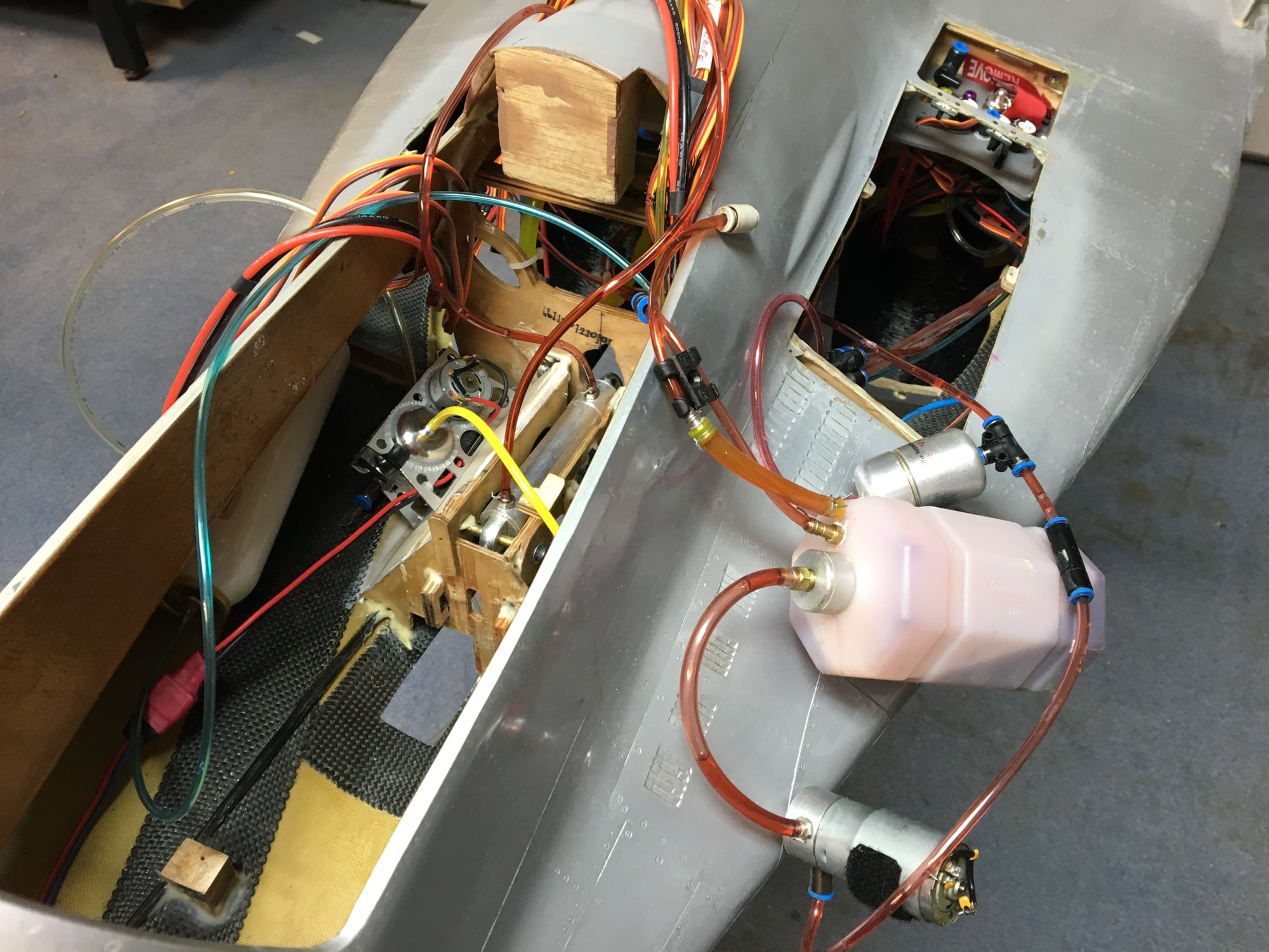
12-31-2018, 11:55 AM
#522


When I built the Mig29 I had here the tanks were a concern to me I made them so they could be removed but I also did them so one tank would feed one uat to one engine. The difference in capacity surprised me. They were within I believe 2 ounces or less of each other it was what I considered negligible. I felt having 2 separate fuel systems was a better choice. Having said that the version I built was the original fiberclassics version. One tank was rectangular and had a notch in it that fit around the wing tube. The other sat on top of that one. I thought I had pictures of how I installed them but cant find them at the moment I'll keep searching.
12-31-2018, 11:59 AM
#523
Sounds like those are the same tanks I'm working with LGM, also same as Spaceman has posted on the previous page - now, how you made them removable would be impressive to say the least. But surprising to hear the capacities are so close.
12-31-2018, 12:12 PM
#524
http://www.rcuniverse.com/forum/rc-jets-120/9970309-major-winter-build-started-few-weeks-comp-arf-mig29-4.html
I used a brace that screws in place to hold it in place. It required removing a number of components but I dont like having tanks that cannot be serviced
12-31-2018, 12:57 PM
#525
Sorry I can,t help you guys, my tanks are quite different from those shown. I have made them removeable, clamped to the wing tubes. Time consuming but can be done.
However, each engine is entirely seperate from the other , with its own tank (s) two small aft in series and one large forward tank.
There is nothing common to both engines. ( Boeing practice , unless you open the crossfeed ! )
All services are accessed via the nose cone, the manual fuel valves are in the gear bays.
The sockets for the ECUs are in a hatch formed by the gun vent panel.

